EP0302223B1 - Conveyor system using automotive cart - Google Patents
Conveyor system using automotive cart Download PDFInfo
- Publication number
- EP0302223B1 EP0302223B1 EP88110379A EP88110379A EP0302223B1 EP 0302223 B1 EP0302223 B1 EP 0302223B1 EP 88110379 A EP88110379 A EP 88110379A EP 88110379 A EP88110379 A EP 88110379A EP 0302223 B1 EP0302223 B1 EP 0302223B1
- Authority
- EP
- European Patent Office
- Prior art keywords
- cart
- automotive
- automotive cart
- conveyor apparatus
- set forth
- Prior art date
- Legal status (The legal status is an assumption and is not a legal conclusion. Google has not performed a legal analysis and makes no representation as to the accuracy of the status listed.)
- Expired - Lifetime
Links
- 230000008054 signal transmission Effects 0.000 claims description 4
- 229920005989 resin Polymers 0.000 claims description 2
- 239000011347 resin Substances 0.000 claims description 2
- 230000003213 activating effect Effects 0.000 claims 1
- 238000010276 construction Methods 0.000 description 5
- 230000005540 biological transmission Effects 0.000 description 4
- 230000004907 flux Effects 0.000 description 4
- 238000007689 inspection Methods 0.000 description 4
- 230000003287 optical effect Effects 0.000 description 4
- 238000012546 transfer Methods 0.000 description 4
- 238000009434 installation Methods 0.000 description 3
- WABPQHHGFIMREM-UHFFFAOYSA-N lead(0) Chemical compound [Pb] WABPQHHGFIMREM-UHFFFAOYSA-N 0.000 description 3
- 238000012423 maintenance Methods 0.000 description 3
- 230000035939 shock Effects 0.000 description 3
- WHXSMMKQMYFTQS-UHFFFAOYSA-N Lithium Chemical compound [Li] WHXSMMKQMYFTQS-UHFFFAOYSA-N 0.000 description 2
- 238000004140 cleaning Methods 0.000 description 2
- 238000012790 confirmation Methods 0.000 description 2
- 238000003780 insertion Methods 0.000 description 2
- 230000037431 insertion Effects 0.000 description 2
- 229910052744 lithium Inorganic materials 0.000 description 2
- 235000021184 main course Nutrition 0.000 description 2
- 230000001174 ascending effect Effects 0.000 description 1
- 230000000694 effects Effects 0.000 description 1
- 230000005489 elastic deformation Effects 0.000 description 1
- 230000005611 electricity Effects 0.000 description 1
- 238000000034 method Methods 0.000 description 1
- 238000003825 pressing Methods 0.000 description 1
- 238000000926 separation method Methods 0.000 description 1
- 229920003002 synthetic resin Polymers 0.000 description 1
- 239000000057 synthetic resin Substances 0.000 description 1
Images





Classifications
-
- B—PERFORMING OPERATIONS; TRANSPORTING
- B65—CONVEYING; PACKING; STORING; HANDLING THIN OR FILAMENTARY MATERIAL
- B65G—TRANSPORT OR STORAGE DEVICES, e.g. CONVEYORS FOR LOADING OR TIPPING, SHOP CONVEYOR SYSTEMS OR PNEUMATIC TUBE CONVEYORS
- B65G15/00—Conveyors having endless load-conveying surfaces, i.e. belts and like continuous members, to which tractive effort is transmitted by means other than endless driving elements of similar configuration
- B65G15/04—Conveyors having endless load-conveying surfaces, i.e. belts and like continuous members, to which tractive effort is transmitted by means other than endless driving elements of similar configuration the load being carried on the lower run of the endless surface
-
- B—PERFORMING OPERATIONS; TRANSPORTING
- B61—RAILWAYS
- B61B—RAILWAY SYSTEMS; EQUIPMENT THEREFOR NOT OTHERWISE PROVIDED FOR
- B61B13/00—Other railway systems
-
- B—PERFORMING OPERATIONS; TRANSPORTING
- B61—RAILWAYS
- B61B—RAILWAY SYSTEMS; EQUIPMENT THEREFOR NOT OTHERWISE PROVIDED FOR
- B61B3/00—Elevated railway systems with suspended vehicles
-
- B—PERFORMING OPERATIONS; TRANSPORTING
- B61—RAILWAYS
- B61C—LOCOMOTIVES; MOTOR RAILCARS
- B61C11/00—Locomotives or motor railcars characterised by the type of means applying the tractive effort; Arrangement or disposition of running gear other than normal driving wheel
- B61C11/04—Locomotives or motor railcars characterised by the type of means applying the tractive effort; Arrangement or disposition of running gear other than normal driving wheel tractive effort applied to racks
-
- B—PERFORMING OPERATIONS; TRANSPORTING
- B61—RAILWAYS
- B61C—LOCOMOTIVES; MOTOR RAILCARS
- B61C13/00—Locomotives or motor railcars characterised by their application to special systems or purposes
- B61C13/04—Locomotives or motor railcars characterised by their application to special systems or purposes for elevated railways with rigid rails
Definitions
- the present invention relates to a conveyor apparatus using an automotive cart used for conveying loads in spaces or factories.
- a conveyor apparatus of this type has been proposed, as in Japanese Utility Model Application Laid-Open No.58-38627, in which an automotive cart (travelling device) is travelled while supported and guided by a rail device.
- Said rail device comprises an automotive cart guiding member having a C letter-shaped section formed in rectangular shape and a duct member having a U letter-shaped section disposed so as to be connected with said automotive cart guiding member.
- a wheel of the cart is engaged with the automotive cart guiding member to carry out the above described support and guide of the cart.
- the automotive cart guiding member is provided with feeding rails, signal-giving and receiving rails and the like laid therewithin.
- the automotive cart is provided with current collectors brought into sliding contact with these rails.
- the duct member is provided with wirings and the like laid therewith, the wirings being connected with the feeding rails.
- a pair of guide faces for guiding a frictional driving wheel means for driving the automotive cart are formed at symmetrical positions with a center of the rail device.
- the rail device can be easily laid without taking a direction thereof and the like into consideration.
- the respective guide faces can be adapted to be capable of being removably fixed thereto a rack engaged with a pinion for travelling the cart.
- a rack engaged with a pinion for travelling the cart.
- the rack can be mounted on the other guide face, which is not used for the frictional driving wheel means, to travel the automotive cart without hindrance.
- the feeding rails for feeding the automotive cart with an electric power can be mounted on an edge and portion for forming the slit of the automotive cart guiding member by utilizing an inserted structure. With such a construction, the installation of the feeding rail on the rail device and the removal of the feeding rail from the rail device can be easily carried out.
- the automotive cart is provided with a bumper, and a means for emitting a stop signal for the cart when bumpers of two carts are brought into contact with each other is provided.
- an information-recording medium can be mounted on the automotive cart.
- An ID card is suitably used as the information-recording medium.
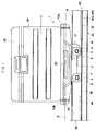
- Reference numeral 1 designates an automotive cart of which body comprises a pair of right and left first wheels 4 idly mounted on a body frame 2 through a first axle 3, a pair of right and left second wheels 7 idly mounted on the body frame 2 through a second axle 6 at positions separated from said first wheel 4 in any one of directions along a predetermined course 5 and side movement-controlling wheels 8, 9 mounted on outer end portions of both wheels 3, 6.
- a motor 10 is disposed in the box-like body frame 2 provided with at least a lower surface opened, said motor 10 being mounted on a middle portion of the body frame 2 in the front and rear direction thereof through a side pin 11 so as to swing up and down.
- the front portion of the motor 10 is swingably energized downward by means of a spring 12 disposed between the motor 10 and the body frame 2.
- Reference numeral 13 designates a stopper for controlling a swinging quantity of the motor 10 against the spring 12.
- a reduction device 14 is connected with the front portion of the motor 10 in an interlocked manner, a propelling rotary wheel (frictional rotary wheel) 16 positioned adjacent to the first wheel 4 being fixedly mounted on one end of a driving shaft 15 extending in the right and left direction from the reduction device 14, and a pinion gear 17 being fixedly mounted on the other end of the driving shaft 15.
- the propelling rotary wheel 16 and the pinion gear 17 are disposed at a substantially equal distance from a center 22 of the automotive cart.
- a pair of right and left current collectors 18A, 18B are disposed on said body frame 2 through a supporting means 23 formed of a plate spring and current collecting positions of these current collectors 18A, 18B are adjacent to the second wheel 7.
- the body frame 2 is provided with a first and second sensor (stop signal receiver) 19, 20 mounted on a front end and rear end thereof, respectively, therebelow and a permanent magnet (automotive cart signal transmitter) 21 mounted on a middle portion thereof. These sensors 19, 20 and the permanent magnet 21 are positioned in a central portion in the direction of width of the cart.
- the body frame 2 is provided with a load housing portion 24 mounted on the upper side thereof, said load housing portion 24 having a closing cover member 25.
- the body frame 2 is provided with bumpers 70A, 70B mounted on the front portion and the rear portion thereof.
- These bumpers 70A, 70B comprise a fitting member 71 formed of rectangular flat plate-like insulating synthetic resin as a base plate, as shown in Figs. 10 to 12, said fitting member 71 being removably mounted on the body frame 2 through a plurality of bolts 72 projected from a rear surface thereof.
- the fitting member 71 is provided with a flexible cover 73 made of electrically conductive rubber and removably mounted on a surface thereof by means of a screw 74 and the like put on a circumferential edge portion 71a thereof.
- the flexible cover 73 comprises a surrounding wall portion 73a fixedly put on the fitting member 71 and an arched front plate member 73b positioned in front of said fitting member 71 with a space 75 therebetween.
- a bellows portion 73c is formed all over the circumference of the surrounding wall portion 73a and a plurality of ribs 73d are provided on an inner surface of the front plate member 73b in the up and down direction to maintain the configuration if necessary.
- a connecting terminal 76 is mounted on the surrounding wall portion 73a of the flexible cover 73 between the flexible cover 73 and the circumferential edge portion 71a of the fitting member 71 in the space 75 within the flexible cover 73.
- a lead wire 77 extending from this connecting terminal 76 is connected with the current collectors 18A, 18B and provided with a stop signal-transmitting device 78 for the motor 10 in a middle portion thereof.
- the cart 1 is provided with an optical ID card connected with the current collectors 18A, 18B.
- a control box 80 is disposed in the body frame 2, said control box 80 being connected with the current collectors 18A, 18B through a lead wire 81.
- the body frame 2 is provided with the ID card 83 on one side surface thereof through a fitting plate 82, said ID card 83 being connected with the control box 80 through a lead wire 84.
- the ID card 83 is provided with a display device 85 in a transmitting window 86, the device 85 being capable of carrying out a plurality of displays, that is, a display of cart number of the automotive cart, display of destination, display of the absence or presence of load and the like.
- the ID card 83 is provided with a lithium cell 87 for using when the current is cut off.
- reference numeral 30 designates a rail device, which is formed symmetrically right and left, for supporting and guiding the cart 1 and comprises an automotive cart guiding member 32 having a C letter-shaped section provided with an opened portion 31 for travelling the cart therethrough formed all over the one surface thereof and a U letter-like duct member 33 connected with an outside of the other surface of said automotive cart guiding member 32.
- the automotive cart guiding member 32 with the opened portion 31 turned upward comprises one plate members 32a provided with first guide surfaces 34 positioned on both sides of the opened portion 31 and engageable with an upper portion of a first wheel 4, the other plate member 32b provided with a second guide surface 35 opposite to said plate members 32a and engageable with a lower portion of a second wheel 7 and side plate members 32c provided with a third guide surface 36 connecting outer ends of both plate members 32a, 32b with each other and engageable with outer portions of side movement-controlling wheels 8, 9.
- the other plate member 32b is provided with a slit 39, for disposing instruments on the rail side, formed in a central portion thereof all over the length thereof, the automotive cart guiding member 32 being communicated with the duct member 33 through this slit 39.
- the plate member 32b is provided with inverted trapezoid-shaped rack-mounting members 32d formed on an inner surface side thereof on both sides of the slit 39 so that the inner surface of these rack-mounting members 32d may serve as frictional tumbling surfaces 37 engageable with a lower portion of the propelling rotary wheel 16.
- a rack 38 which is engaged with the pinion gear 17 in an inclined course, a vertical course and the like, is mounted on any one of both rack-mounting members 32d by inserting and the like.
- Such the rail device 30 is formed symmetrically right and left relatively to a rail center 29.
- the width L1 of the slit 39 is adapted to be smaller than that L2 of the duct member 33.
- An edge portion for forming the slit 39 in the automotive cart guiding member 32 is provided with insulating rod members 40A, 40B put thereon. These insulating rod members 40A, 40B are provided with feeding rails 41A, 41B brought into sliding contact with current collectors 18A, 18B. As shown in Figs. 5 and 6, the other plate member 32b provided with the slit 39 is provided with convex first engaging members 61A, 61B formed in the edge portion thereof on both surfaces in the direction of plate thickness all over the length thereof.
- the insulating rod members 40A, 40B formed of resins are provided with putting-on concave grooves 62A, 62B engageable sideways with the inner edge portion of said other plate member 32b.
- the putting-on concave grooves 62A, 62B are provided with concave groove-like first engaging members 63A, 63B in the direction of plate thickness which are engageable with the first engaging members 61A, 61B formed on both of an upper inner surface and a lower inner surface thereof.
- the insulating rod members 40A, 40B are provided with insertion grooves 64A, 64B disposed at positions shifted from the putting-on concave grooves 62A, 62B and opened toward an opposite side formed all over the length thereof.
- Concave groove-like second engaging members 65A, 65B in the direction of plate thickness of the plate member 32b are formed on a surface of the side of the opened portion 31 all over the length thereof.
- the feeding rails 41A, 41B are provided with inserting piece members 66A, 66B insertable sideways into the insertion grooves 64A, 64B, and convex second engaging members 67A, 67B engageable in the direction of plate thickness of the plate member 32b with the second engaging members 65A, 65B are formed all over the length of the feeding rails 41A, 41B.
- a rail side instrument 42 on the rail side disposed over the slit 39 to the duct 33 comprises for example a pair of right and left magnetic pole plates 43A, 43B, a pair of front and rear coils (stop signal transmitters) 44, 45 disposed between said magnetic pole plates 43A, 43B and a third sensor (automotive cart signal receiver) 46.
- Both magnetic pole plates 43A, 43B are engaged with projections 47A, 47B formed integrally with the bottom plate member of the duct member 33 at lower ends thereof, whereby positioning the rail side instrument 42.
- the upper ends of the magnetic pole plates 43A, 43B are basically projected into the automotive cart guiding member 32, as shown in Fig. 5, to be positioned on both sides of the first sensor 19, the second sensor 20 and the permanent magnet 21 which are automotive cart side instruments.
- the magnetic pole plate 43B positioned in the outer side of the curve is formed low, as shown in for example Fig. 2.
- a plurality of wiring 48 which are connected with the feeding rails 41A, 41B or the instruments 42, are housed in the duct member 33.
- the wiring 48 are disposed on the inner surface of the duct member 33 through fitting members 49.
- the width L2 of the duct member 33 is formed to be smaller than that L3 of the automotive cart guiding member 32, so that both side surfaces of the rail device 30 are formed in a stepped shape.
- the sides of the duct member 33 are provided with concave constructing engaging members 50 formed at ends thereof.
- a constructing member 51 on the floor side for arranging the opened portion 31 upward comprises a pair of engaging pieces 52 engageable from outside with said engaging members 50, a bolt 53 and a nut 54 for tightly connecting the engaging pieces 52 with each other, a base frame 56 for supporting both engaging pieces 52 through fitting members (bolts and nuts) 55 and the like.
- a constructing member 57 on the ceiling side for arranging the opened portion 31 downward comprises a pair of engaging pieces 52 engageable from outside with the engaging members 50, a gangway member 59 disposed between the engaging pieces 52 through bolts 58 and hanging rods 60 tightly connected with both engaging pieces 52.
- the predetermined course 5 comprises, as shown in Fig. 17, for example a circular main course portion 5a, a storage portion 5b and a branched course portion 5c connected with said circular main course portion 5a through a branch-junction device 90 and the like, stations 91 being formed in the storage portion 5b and the branched course portion 5c.
- the respective stations 91 and a main station 92 are provided with a transfer unit 93 to which the ID card 83 can be disposed opposite.
- These transfer units 93 comprise a transfer window 94, as shown in Figs. 2, 16 and 17.
- Lead wires 95 are connected with a controlling device 96 disposed in the main station 92.
- the instruments 42 on the rail side are disposed at specified places along the direction of the predetermined course 5.
- the respective wirings 48 are connected with the controlling device 96.
- the rail device 30 In the disposition of the rail device 30 through the constructing member 51 on the floor side, the constructing member 57 on the ceiling side and the like, the rail device 30 can be mounted regardless of the right and left direction thereof.
- the propelling rotary wheel 16 of the automotive cart 1, turning right or left relatively to a center 22 of the automotive cart 1 depending upon the travelling direction of the automotive cart 1, is pressed against any one of frictional tumbling surfaces 37 of both rack-mounting members 32d to be tumbled.
- the pinion gear 17 In the inclined course, the vertical course or the like, the pinion gear 17 is engageable with a rack 38 mounted on a remaining rack-mounting member 32d not utilizing the frictional tumbling surface 37.
- the travelling of the automotive cart 1 is carried out by transmitting a turning force of the motor 10 to the propelling rotary wheel 16 through the reduction device 14 and the driving shaft 15, and pressing the propelling rotary wheel 16 against the frictional tumbling surface 37 to tumble on the surface 37.
- the travelling is stably carried out on the predetermined course 5, such as the horizontal course or the inclined course, under the condition of no shaking and the like by the tumbling of the first wheel 4 on the first travelling and guiding surface 34, the tumbling of the second wheel 7 on the second travelling and guiding surface 35 and the tumbling of the side movement-controlling wheels 8, 9 on the third travelling and guiding surface 36.
- the travelling without slip can be achieved by engaging the pinion gear 17 with the rack 38.
- the sensors 19, 20 passing through the portion located between both magnetic pole plates 43A, 43B do not receive the stop signal.
- the detected signal is given to the controlling device 96 through the wirings 48.
- the colis 44, 45 corresponding to the specified places are electrified before the automotive cart 1 reaches there.
- a magnetic flux (stop signal) B in the right and left direction is formed between the upper ends of both magnetic pole plates 43A, 43B, whereby the sensors 19, 20, which have travelled integrally with the automotive cart 1, detect the magnetic flux B to stop the motor 10 and effect the brake.
- the cart 1 is travelled by the braking distance and then stopped.
- the permanent magnet 21 is opposite to the sensor 46 to detect the magnetic flux A in the same manner as described above, whereby the confirmation of the stopping is carried out in the controlling device 96.
- the cart 1 is swung outside of the curve by a centrifugal force, whereby also the sensors 19, 20 and the permanent magnet 21 are moved outside. But in this time, as shown in Fig. 2, the outside one of the magnetic pole plates 43A, 43B is formed lower, so that they do not come into collision with each other.
- the destination information of the cart 1 is read out in the vicinity of the branch-junction point or the station to judge whether the cart 1 is to be stopped or not.
- the optical transmission is carried out between the ID card 83 and the transmission unit 93 under the condition that the cart 1 is stopped at the stations 91, 92 on the basis of the obtained judgement.
- the controlling device 96 it can be found by reading out the display of the cart number of the display device 85 that the automotive cart of which cart number is positioned at which station 91.
- the writing-in optical signal is given from the transmission unit 93 in correspondence to the change in loading condition to rewrite the ID card 83.
- the new destination is set for the stopped cart 1 by the writing-in optical signal from the transmission unit 93 and then the cart 1 is started.
- An electric power collected by the current collectors 18A, 18B is given to the ID card 83 through the control box 80, so that the power source can be easily obtained. During the time when the electricity fails, the information can be prevented from being gone out with the help of the lithium cell 87.
- the rear bumper 70B of the preceding cart 1A is separated from the front bumper 70A of the following cart 1B to break the electrification therebetween and start to drive the motor 10 of the following cart 1B, whereby also the following cart 1B is travelled again and then stopped at the specified place.
- the following automotive carts 1B, 1D come into collision with the preceding automotive carts 1A, 1C with forming various angles therebetween. But in that time, the rear bumper 70B of the preceding carts 1A, 1C is merely brought into contact with the front bumper 70A of the following carts 1B, 1D by the flexible covers 73 thereof, and the collision force between both carts is absorbed by the bellows-like member 73c, so that the carts do not repeat the collision and the separation due to the impetus when came into collision with each other.
- the cleaning and the installation of the instruments 42 on the rail side as well as various kinds of wiring operation within the duct member 33, the maintenance and inspection after the wiring, and the inspection, confirmation, replacement and change in arrangement of the instruments 42 on the rail side are carried out through the opened portion 31 and the slit 39. These operation is carried out under the condition that the rail device 30 is installed on the ceiling side by means of the constructing member 57, or on the floor side by means of the constructing member 51.
- the automotive cart 1 is provided with the sensors 19, 20 mounted on both the front end and the rear end thereof in the above described embodiment, only one sensor may be used.
- the use of two sensors leads to the operation of the rear sensor when the overrun of the cart occurs and thus to the satisfactory travelling in both the forward direction and the rearward direction.
- the instruments 42 on the rail side comprise the coils 44, 45 and the third sensor 46 in the form of one set in the above described embodiment, the third sensor 46 may be disposed in a separated manner.
- the feeding rails 41A, 41B may be detachably provided with the insulating cover for opening and closing the slit 39 all over the opposite inner surfaces thereof.
Landscapes
- Engineering & Computer Science (AREA)
- Mechanical Engineering (AREA)
- Transportation (AREA)
- Platform Screen Doors And Railroad Systems (AREA)
- Non-Mechanical Conveyors (AREA)
- Control Of Position, Course, Altitude, Or Attitude Of Moving Bodies (AREA)
Description
- The present invention relates to a conveyor apparatus using an automotive cart used for conveying loads in spaces or factories.
- A conveyor apparatus of this type has been proposed, as in Japanese Utility Model Application Laid-Open No.58-38627, in which an automotive cart (travelling device) is travelled while supported and guided by a rail device. Said rail device comprises an automotive cart guiding member having a C letter-shaped section formed in rectangular shape and a duct member having a U letter-shaped section disposed so as to be connected with said automotive cart guiding member. A wheel of the cart is engaged with the automotive cart guiding member to carry out the above described support and guide of the cart. The automotive cart guiding member is provided with feeding rails, signal-giving and receiving rails and the like laid therewithin. The automotive cart is provided with current collectors brought into sliding contact with these rails. The duct member is provided with wirings and the like laid therewith, the wirings being connected with the feeding rails.
- With the above described conventional type, a disadvantage occurs in that the inner portion of the duct is closed up tight, the constructing operation of wirings and the maintenance and inspection of wirings after the construction being difficult, and increased man-hours being required.
- It is an object of the present invention to provide a conveyor system which can withstand large load.
- In order to achieve these objects, a conveyor apparatus using an automotive cart according to the present invention, This object is achieved by means of the feature of the characterising part of claim 1.
- With such a construction, the cleaning of the inside of the duct member, the installation of various kinds of instrument and the wiring operation in this duct member, the maintenance and inspection after the wiring and the like can be easily carried out through the opened portion and the slit.
- In addition, according to the present invention, a pair of guide faces for guiding a frictional driving wheel means for driving the automotive cart are formed at symmetrical positions with a center of the rail device. Thus, the rail device can be easily laid without taking a direction thereof and the like into consideration.
- The respective guide faces can be adapted to be capable of being removably fixed thereto a rack engaged with a pinion for travelling the cart. Thus, only any one of the guide faces can be used for guiding the frictional driving wheel means. And, at the places where the rail device is arranged in the vertical or inclined condition, the rack can be mounted on the other guide face, which is not used for the frictional driving wheel means, to travel the automotive cart without hindrance.
- According to the present invention, the feeding rails for feeding the automotive cart with an electric power can be mounted on an edge and portion for forming the slit of the automotive cart guiding member by utilizing an inserted structure. With such a construction, the installation of the feeding rail on the rail device and the removal of the feeding rail from the rail device can be easily carried out.
- In addition, according to the present invention, the automotive cart is provided with a bumper, and a means for emitting a stop signal for the cart when bumpers of two carts are brought into contact with each other is provided. With such a construction, not only the shock, which is produced when the carts come into collision with each other, can be absorbed by the bumper but also the following cart can be easily stopped when it comes into collision with the preceding cart.
- In addition, according to the present invention, an information-recording medium can be mounted on the automotive cart. Thus, the travelling of the cart can be easily and surely controlled. An ID card is suitably used as the information-recording medium.
-
- Fig. 1 is a general view showing an automotive cart according to a first embodiment of an apparatus of the present invention;
- Fig. 2 is a cross section showing main portion of the automotive cart shown in Fig. 1 together with a sectional construction of a rail device;
- Fig. 3 is a front view showing the automotive cart and the rail device shown in Fig. 2;
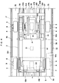
- Fig. 4 is a plan view showing the automotive cart and the rail device shown in Fig. 3;
- Fig. 5 is a detailed drawing showing feeding rails according to the present invention;
- Fig. 6 is a perspective view showing an assembling method of the feeding rails shown in Fig. 5;
- Figs. 7 and 8 are schematic drawings showing a manner of giving and receiving signals between the rail device and the automotive cart according to the present invention;
- Fig. 9 is a cross section showing an apparatus according to the present invention in the case where the rail device is mounted on a ceiling;
- Figs. 10 to 12 are sectional views showing a sectional view of a bumper according to the present invention and an action of the bumper;
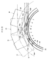
- Figs. 13 and 14 are schematic drawings showing a positional relation between two carts at a place where the rail device is formed in a bent condition;
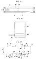
- Fig. 15 is a schematic drawing showing an ID card according to the present invention;
- Fig. 16 is a schematic drawing showing a transfer unit for the ID card shown in Fig. 15; and
- Fig. 17 is a schematic drawing showing one example of a layout of a conveyor apparatus according to the present invention.
- One preferred embodiment of the present invention will be below described with reference to the drawings.
- Reference numeral 1 designates an automotive cart of which body comprises a pair of right and left
first wheels 4 idly mounted on abody frame 2 through afirst axle 3, a pair of right and leftsecond wheels 7 idly mounted on thebody frame 2 through asecond axle 6 at positions separated from saidfirst wheel 4 in any one of directions along apredetermined course 5 and side movement-controllingwheels wheels motor 10 is disposed in the box-like body frame 2 provided with at least a lower surface opened, saidmotor 10 being mounted on a middle portion of thebody frame 2 in the front and rear direction thereof through aside pin 11 so as to swing up and down. The front portion of themotor 10 is swingably energized downward by means of aspring 12 disposed between themotor 10 and thebody frame 2.Reference numeral 13 designates a stopper for controlling a swinging quantity of themotor 10 against thespring 12. Areduction device 14 is connected with the front portion of themotor 10 in an interlocked manner, a propelling rotary wheel (frictional rotary wheel) 16 positioned adjacent to thefirst wheel 4 being fixedly mounted on one end of adriving shaft 15 extending in the right and left direction from thereduction device 14, and apinion gear 17 being fixedly mounted on the other end of thedriving shaft 15. The propellingrotary wheel 16 and thepinion gear 17 are disposed at a substantially equal distance from acenter 22 of the automotive cart. A pair of right and leftcurrent collectors body frame 2 through a supportingmeans 23 formed of a plate spring and current collecting positions of thesecurrent collectors second wheel 7. Thebody frame 2 is provided with a first and second sensor (stop signal receiver) 19, 20 mounted on a front end and rear end thereof, respectively, therebelow and a permanent magnet (automotive cart signal transmitter) 21 mounted on a middle portion thereof. Thesesensors permanent magnet 21 are positioned in a central portion in the direction of width of the cart. Thebody frame 2 is provided with aload housing portion 24 mounted on the upper side thereof, saidload housing portion 24 having aclosing cover member 25. - The
body frame 2 is provided withbumpers bumpers fitting member 71 formed of rectangular flat plate-like insulating synthetic resin as a base plate, as shown in Figs. 10 to 12, said fittingmember 71 being removably mounted on thebody frame 2 through a plurality ofbolts 72 projected from a rear surface thereof. Thefitting member 71 is provided with aflexible cover 73 made of electrically conductive rubber and removably mounted on a surface thereof by means of ascrew 74 and the like put on a circumferential edge portion 71a thereof. Theflexible cover 73 comprises a surroundingwall portion 73a fixedly put on thefitting member 71 and an archedfront plate member 73b positioned in front of said fittingmember 71 with aspace 75 therebetween. Abellows portion 73c is formed all over the circumference of the surroundingwall portion 73a and a plurality ofribs 73d are provided on an inner surface of thefront plate member 73b in the up and down direction to maintain the configuration if necessary. A connectingterminal 76 is mounted on the surroundingwall portion 73a of theflexible cover 73 between theflexible cover 73 and the circumferential edge portion 71a of thefitting member 71 in thespace 75 within theflexible cover 73. Alead wire 77 extending from this connectingterminal 76 is connected with thecurrent collectors device 78 for themotor 10 in a middle portion thereof. When thebumpers bumpers device 78 is operated. - As shown in Figs. 1, 2 and 15, the cart 1 is provided with an optical ID card connected with the
current collectors control box 80 is disposed in thebody frame 2, saidcontrol box 80 being connected with thecurrent collectors body frame 2 is provided with theID card 83 on one side surface thereof through afitting plate 82, saidID card 83 being connected with thecontrol box 80 through alead wire 84. TheID card 83 is provided with adisplay device 85 in a transmittingwindow 86, thedevice 85 being capable of carrying out a plurality of displays, that is, a display of cart number of the automotive cart, display of destination, display of the absence or presence of load and the like. Furthermore, theID card 83 is provided with alithium cell 87 for using when the current is cut off. - Referring to Figs. 1 to 6,
reference numeral 30 designates a rail device, which is formed symmetrically right and left, for supporting and guiding the cart 1 and comprises an automotivecart guiding member 32 having a C letter-shaped section provided with an openedportion 31 for travelling the cart therethrough formed all over the one surface thereof and a U letter-like duct member 33 connected with an outside of the other surface of said automotivecart guiding member 32. For example, the automotivecart guiding member 32 with the openedportion 31 turned upward comprises oneplate members 32a provided with first guide surfaces 34 positioned on both sides of the openedportion 31 and engageable with an upper portion of afirst wheel 4, theother plate member 32b provided with asecond guide surface 35 opposite to saidplate members 32a and engageable with a lower portion of asecond wheel 7 andside plate members 32c provided with athird guide surface 36 connecting outer ends of bothplate members wheels - The
other plate member 32b is provided with aslit 39, for disposing instruments on the rail side, formed in a central portion thereof all over the length thereof, the automotivecart guiding member 32 being communicated with theduct member 33 through thisslit 39. Theplate member 32b is provided with inverted trapezoid-shaped rack-mountingmembers 32d formed on an inner surface side thereof on both sides of theslit 39 so that the inner surface of these rack-mountingmembers 32d may serve as frictional tumblingsurfaces 37 engageable with a lower portion of the propellingrotary wheel 16. Arack 38, which is engaged with thepinion gear 17 in an inclined course, a vertical course and the like, is mounted on any one of both rack-mountingmembers 32d by inserting and the like. Such therail device 30 is formed symmetrically right and left relatively to arail center 29. The width L₁ of theslit 39 is adapted to be smaller than that L₂ of theduct member 33. - An edge portion for forming the
slit 39 in the automotivecart guiding member 32 is provided with insulatingrod members
These insulatingrod members rails current collectors other plate member 32b provided with theslit 39 is provided with convex firstengaging members 61A, 61B formed in the edge portion thereof on both surfaces in the direction of plate thickness all over the length thereof. The insulatingrod members concave grooves other plate member 32b. The putting-onconcave grooves engaging members members 61A, 61B formed on both of an upper inner surface and a lower inner surface thereof. The insulatingrod members insertion grooves concave grooves engaging members plate member 32b are formed on a surface of the side of the openedportion 31 all over the length thereof. The feeding rails 41A, 41B are provided with insertingpiece members insertion grooves engaging members plate member 32b with the secondengaging members - A
rail side instrument 42 on the rail side disposed over theslit 39 to theduct 33 comprises for example a pair of right and leftmagnetic pole plates magnetic pole plates magnetic pole plates projections duct member 33 at lower ends thereof, whereby positioning therail side instrument 42. The upper ends of themagnetic pole plates cart guiding member 32, as shown in Fig. 5, to be positioned on both sides of thefirst sensor 19, thesecond sensor 20 and thepermanent magnet 21 which are automotive cart side instruments. In the curved course, themagnetic pole plate 43B positioned in the outer side of the curve is formed low, as shown in for example Fig. 2. - A plurality of
wiring 48, which are connected with the feeding rails 41A, 41B or theinstruments 42, are housed in theduct member 33. Thewiring 48 are disposed on the inner surface of theduct member 33 throughfitting members 49. - The width L₂ of the
duct member 33 is formed to be smaller than that L₃ of the automotivecart guiding member 32, so that both side surfaces of therail device 30 are formed in a stepped shape. The sides of theduct member 33 are provided with concaveconstructing engaging members 50 formed at ends thereof. A constructingmember 51 on the floor side for arranging the openedportion 31 upward comprises a pair of engagingpieces 52 engageable from outside with said engagingmembers 50, abolt 53 and anut 54 for tightly connecting the engagingpieces 52 with each other, abase frame 56 for supporting both engagingpieces 52 through fitting members (bolts and nuts) 55 and the like. - As shown in Fig. 9, a constructing
member 57 on the ceiling side for arranging the openedportion 31 downward comprises a pair of engagingpieces 52 engageable from outside with the engagingmembers 50, agangway member 59 disposed between the engagingpieces 52 throughbolts 58 and hangingrods 60 tightly connected with both engagingpieces 52. - The
predetermined course 5 comprises, as shown in Fig. 17, for example a circularmain course portion 5a, astorage portion 5b and abranched course portion 5c connected with said circularmain course portion 5a through a branch-junction device 90 and the like,stations 91 being formed in thestorage portion 5b and the branchedcourse portion 5c. Therespective stations 91 and amain station 92 are provided with atransfer unit 93 to which theID card 83 can be disposed opposite. Thesetransfer units 93 comprise atransfer window 94, as shown in Figs. 2, 16 and 17. Leadwires 95 are connected with a controllingdevice 96 disposed in themain station 92. Theinstruments 42 on the rail side are disposed at specified places along the direction of thepredetermined course 5. Therespective wirings 48 are connected with the controllingdevice 96. - In the disposition of the
rail device 30 through the constructingmember 51 on the floor side, the constructingmember 57 on the ceiling side and the like, therail device 30 can be mounted regardless of the right and left direction thereof. The propellingrotary wheel 16 of the automotive cart 1, turning right or left relatively to acenter 22 of the automotive cart 1 depending upon the travelling direction of the automotive cart 1, is pressed against any one of frictional tumblingsurfaces 37 of both rack-mountingmembers 32d to be tumbled. In the inclined course, the vertical course or the like, thepinion gear 17 is engageable with arack 38 mounted on a remaining rack-mountingmember 32d not utilizing the frictional tumblingsurface 37. - The travelling operation of the automotive cart 1 in the above described preferred embodiment is below described.
- The travelling of the automotive cart 1 is carried out by transmitting a turning force of the
motor 10 to the propellingrotary wheel 16 through thereduction device 14 and the drivingshaft 15, and pressing the propellingrotary wheel 16 against the frictional tumblingsurface 37 to tumble on thesurface 37. In this time, the travelling is stably carried out on thepredetermined course 5, such as the horizontal course or the inclined course, under the condition of no shaking and the like by the tumbling of thefirst wheel 4 on the first travelling and guidingsurface 34, the tumbling of thesecond wheel 7 on the second travelling and guidingsurface 35 and the tumbling of the side movement-controllingwheels surface 36. In the ascending and descending inclined course portion or vertical course portion, the travelling without slip can be achieved by engaging thepinion gear 17 with therack 38. - During such the travelling, when the
coils sensors magnetic pole plates permanent magnet 21 by thethird sensor 46, that the automotive cart 1 passed the place where thethird sensor 46 is disposed (exists in a certain section). The detected signal is given to the controllingdevice 96 through thewirings 48. In order to stop the specified automotive cart 1 at the specified places (stations) 91, 92 and the like, thecolis magnetic pole plates sensors motor 10 and effect the brake. Thus, the cart 1 is travelled by the braking distance and then stopped. As a result, thepermanent magnet 21 is opposite to thesensor 46 to detect the magnetic flux A in the same manner as described above, whereby the confirmation of the stopping is carried out in the controllingdevice 96. - During the travelling in the curved course the cart 1 is swung outside of the curve by a centrifugal force, whereby also the
sensors permanent magnet 21 are moved outside. But in this time, as shown in Fig. 2, the outside one of themagnetic pole plates - During the travelling of the cart 1, the destination information of the cart 1 is read out in the vicinity of the branch-junction point or the station to judge whether the cart 1 is to be stopped or not. The optical transmission is carried out between the
ID card 83 and thetransmission unit 93 under the condition that the cart 1 is stopped at thestations device 96, it can be found by reading out the display of the cart number of thedisplay device 85 that the automotive cart of which cart number is positioned at whichstation 91. In addition, if necessary, by displaying a load-loadless discriminating number and a destined station number on thedisplay device 85, it is read out and judged by a signal from the ground side whether the automotive cart 1 is loaded or not and where is the destination of the cart 1. Further, when the loading condition is changed in the loading or unloading operation, the writing-in optical signal is given from thetransmission unit 93 in correspondence to the change in loading condition to rewrite theID card 83. The new destination is set for the stopped cart 1 by the writing-in optical signal from thetransmission unit 93 and then the cart 1 is started. An electric power collected by thecurrent collectors ID card 83 through thecontrol box 80, so that the power source can be easily obtained. During the time when the electricity fails, the information can be prevented from being gone out with the help of thelithium cell 87. - As shown by for example a full line in Fig. 13, when the preceding automotive cart 1A comes into collision with the following cart 1B under the condition that the former is stopped at the specified place in the course curved in the upper and lower direction, the latter is automatically stopped. When the
rear bumper 70B of the preceding cart 1A comes into collision with thefront bumper 70A of the following cart 1B, the shock is absorbed by an elastic deformation of theflexible cover 73 of bothbumpers member 73c to moderate the shock and prevent both carts 1A, 1B from repeatedly separating from and coming into collision with each other. When theflexible cover 73 of thefront bumper 70A of the following cart 1B is brought into contact with theflexible cover 73 of therear bumper 70B of the preceding cart 1A, a current flows between both carts 1A, 1B through bothflexible covers signal transmission device 78, whereby themotor 10 is automatically stopped driving and the travelling force is lost to stop the cart 1B. In this time, since the circuit is previously set so that the stopsignal transmission device 78 may not take part in themotor 10 of the preceding cart 1A, the desired travelling control of the preceding cart 1A is not affected at all. Subsequently, when the preceding cart 1A is travelled again, therear bumper 70B of the preceding cart 1A is separated from thefront bumper 70A of the following cart 1B to break the electrification therebetween and start to drive themotor 10 of the following cart 1B, whereby also the following cart 1B is travelled again and then stopped at the specified place. - As shown by the imaginary line in Fig. 13, also in the case where the following cart 1D, which has travelled in the horizontal course portion, comes into collision with the preceding cart 1C stopping at the specified place, the following cart 1D is automatically stopped in the same manner. In addition, also in the plane curved course portion shown in Fig. 14, also in the case where the following cart 1B, which has travelled in the curved course, or the following cart 1D, which has travelled in the straight course portion, comes into collision with the preceding cart 1A stopping at the specified place, these following carts 1B, 1D are automatically stopped in the same manner.
- As shown in Figs. 13 and 14, the following automotive carts 1B, 1D come into collision with the preceding automotive carts 1A, 1C with forming various angles therebetween. But in that time, the
rear bumper 70B of the preceding carts 1A, 1C is merely brought into contact with thefront bumper 70A of the following carts 1B, 1D by the flexible covers 73 thereof, and the collision force between both carts is absorbed by the bellows-likemember 73c, so that the carts do not repeat the collision and the separation due to the impetus when came into collision with each other. Even though the preceding carts 1A, 1C are moved forward to some extent, the contact is not lost and the electrification is speedily and surely carried out between the preceding and following carts to automatically stop the following carts 1B, 1D. Accordingly, the following carts 1B, 1D are securely stopped even though the following carts 1B, 1D come into collision with the preceding carts 1A, 1C in any direction. - In the above described embodiment, the cleaning and the installation of the
instruments 42 on the rail side as well as various kinds of wiring operation within theduct member 33, the maintenance and inspection after the wiring, and the inspection, confirmation, replacement and change in arrangement of theinstruments 42 on the rail side are carried out through the openedportion 31 and theslit 39. These operation is carried out under the condition that therail device 30 is installed on the ceiling side by means of the constructingmember 57, or on the floor side by means of the constructingmember 51. - Although the automotive cart 1 is provided with the
sensors - Although the
instruments 42 on the rail side comprise thecoils third sensor 46 in the form of one set in the above described embodiment, thethird sensor 46 may be disposed in a separated manner. - Furthermore, the feeding rails 41A, 41B may be detachably provided with the insulating cover for opening and closing the
slit 39 all over the opposite inner surfaces thereof.
Claims (8)
- A conveyor apparatus using an automotive cart (1) provided with a rail device (30) for supporting and guiding said automotive cart (1), said rail device (30) comprising an automotive cart guiding member (32) of substantially C-shaped section, said automotive cart guiding member (32) including a plate member (32b) which is divided into two halves by a longitudinally extending central slit (39), one half of said plate member (32b) being provided with a rack (38) meshed, in use, with a pinion (17) rotatably mounted on said automotive cart (1), and other half of said plate member (32b) having a supporting surface (37) on which a wheel (16) rotatably mounted on said automotive cart (1) is adapted to roll, said slit (39) having edges provided with insulating means (40A, 40B) and current conducting means (41A, 41B) applied to said insulating means (40A, 40B), said current conducting means (41A, 41B) being in contact with current collector means (18A, 18B) mounted on said automotive cart (1), a duct member (33) being disposed external to and formed integrally with said automotive cart guiding member (32), characterized in that said duct member (33) has side walls connected respectively to said two halves of said plate member (32b) at the transversely central portion of each half of said plate member (32b).
- A conveyor apparatus as set forth in claim 1, wherein the automotive cart guiding member (32) is provided with a pair of guide surfaces (35) formed in the direction of length of the rail device (30) so as to be positioned on both sides of the slit (39) for guiding frictional tumbling wheel means for travelling and driving the automotive cart (1) therewithin, said pair of guide surfaces (35) being formed at symmetrical positions with a center of the rail device (30).
- A conveyor apparatus as set forth in claim 1 or 2, wherein a stripe member (32d) is formed on said plate member (32b) in the direction of length of the rail device (30) and the rack (38) is fixedly mounted on this stripe member (32d).
- A conveyor apparatus as set forth in Claim 1, wherein the plate member (32b) is provided with an edge end member for forming the slit (39) and said conveyor apparatus is provided with a feeding means mounted on said edge end member and capable of feeding the automotive cart (1) with an electric power.
- A conveyor apparatus as set forth in Claim 4, wherein said edge end member is provided with an insulating rod member (40A, 40B) formed of resins put thereon from the side direction thereof and a feeding rail (41A, 41B) put on said insulating rod member (40A, 40B) on the edge end member thereof, said edge end member being provided with a first engaging member (61A, 61B) formed in the direction of thickness thereof on a surface thereof, said insulating rod member (40A, 40B) comprising an outside groove (62A, 62B) adapted to be put on said edge end member, a second engaging member (63A, 63B) formed within said outside groove (62A, 62B) and capable of engaging with said first engaging member (61A, 61B), a second groove (64A, 64B) formed toward a direction opposite to said outside groove (62A, 62B), and a third engaging member (65A, 65B) formed in a direction of thickness of said plate member (32b), and said feeding rail (41A, 41B) comprising an inserting piece member (66A, 66B) capable of being inserted into said second groove (64A, 64B) and a fourth engaging member (67A, 67B) capable of being engaged with said third engaging member (65A, 65B).
- A conveyor apparatus as set forth in Claim 4, wherein the automotive cart (1) is provided with bumper means (70A, 70B) in a front portion and a rear portion respectively thereof, the respective bumper means (70A, 70B) being provided with a fitting member (71) for fitting the bumper means (70A, 70B) to the automotive cart (1) and a flexible cover (73), having a bellows portion (73C), formed on a front surface of said fitting member (71), and said bumper means (70A, 70B) being capable of being connected with the feeding rail (41A, 41B) through a stop signal transmission device (78) so that a circuit for activating said stop signal transmission device (78) can be formed over adjacent automotive carts (1) when the bumper means (70A, 70B) of both automotive carts are brought into contact with each other.
- A conveyor apparatus as set forth in Claim 1, further comprising an information recording medium, which can optically read and write, mounted on the automotive cart (1) and a means (93), disposed by the side of the rail device (30), capable of writing the information to said information recording medium and reading out the information therefrom.
- A conveyor apparatus as set forth in Claim 7, wherein said information recording medium is an identity card (83).
Applications Claiming Priority (4)
| Application Number | Priority Date | Filing Date | Title |
|---|---|---|---|
| JP194118/87 | 1987-08-03 | ||
| JP62194118A JPS6441461A (en) | 1987-08-03 | 1987-08-03 | Transport device using self traveling vehicle |
| JP173524/87U | 1987-11-13 | ||
| JP1987173524U JPH0177565U (en) | 1987-11-13 | 1987-11-13 |
Publications (3)
| Publication Number | Publication Date |
|---|---|
| EP0302223A2 EP0302223A2 (en) | 1989-02-08 |
| EP0302223A3 EP0302223A3 (en) | 1990-01-10 |
| EP0302223B1 true EP0302223B1 (en) | 1993-12-08 |
Family
ID=26495471
Family Applications (1)
| Application Number | Title | Priority Date | Filing Date |
|---|---|---|---|
| EP88110379A Expired - Lifetime EP0302223B1 (en) | 1987-08-03 | 1988-06-29 | Conveyor system using automotive cart |
Country Status (6)
| Country | Link |
|---|---|
| US (1) | US4944230A (en) |
| EP (1) | EP0302223B1 (en) |
| KR (1) | KR930003067B1 (en) |
| DE (1) | DE3886123T2 (en) |
| GB (1) | GB2207897B (en) |
| SG (1) | SG35092G (en) |
Families Citing this family (9)
| Publication number | Priority date | Publication date | Assignee | Title |
|---|---|---|---|---|
| DE4014698A1 (en) * | 1990-05-08 | 1991-11-14 | Bosch Gmbh Robert | Workpiece transport system with drive blocking mechanisms - on carriages cooperated by sensors detecting characteristic property of transport path surface |
| US5355804A (en) * | 1991-12-13 | 1994-10-18 | Garcia Eduardo R | Rail-guided apparatus-carrying system |
| US6561103B2 (en) * | 2001-09-05 | 2003-05-13 | Peck Assembly Systems, Inc. | Pallet conveyor system |
| KR100805861B1 (en) * | 2005-09-07 | 2008-02-21 | 전봉균 | Unmanned Cargo Transport System using Monorail |
| JP4887804B2 (en) * | 2006-01-26 | 2012-02-29 | 村田機械株式会社 | Transport system |
| US8978905B2 (en) | 2010-07-02 | 2015-03-17 | Liko Research & Development Ab | Lift systems with continuous in-rail charging |
| DE102013005843A1 (en) * | 2013-03-27 | 2014-05-28 | Eisenmann Ag | Marker display device for use on trolley of electric overhead conveyer system in warehouse management field, has display panel forming segment indicator and matrix display fields, where panel provides more than one specific characters |
| US9879457B1 (en) * | 2015-02-05 | 2018-01-30 | Weldon Industries, Inc. | Trolley and track |
| DE102015003736A1 (en) * | 2015-03-21 | 2016-09-22 | Eisenmann Se | Transport trolley and equipment for transporting objects |
Family Cites Families (18)
| Publication number | Priority date | Publication date | Assignee | Title |
|---|---|---|---|---|
| GB737449A (en) * | 1951-10-29 | 1955-09-28 | Donald Mayer King | Improvements in or relating to conveyors |
| US2725973A (en) * | 1951-10-29 | 1955-12-06 | King Donald Mayer | Trolley conveyor |
| GB728301A (en) * | 1952-07-17 | 1955-04-20 | Donald Mayer King | Improvements in or relating to conveyor systems |
| FR1389245A (en) * | 1964-03-28 | 1965-02-12 | Translift G M B H Fuer Buerora | Automatic mail transport installation in buildings |
| US3521568A (en) * | 1967-08-22 | 1970-07-21 | Sanki Eng Co Ltd | Cable tow conveyor |
| SE323629B (en) * | 1967-10-05 | 1970-05-04 | Hansen C Maskinfabrik As | |
| GB1289961A (en) * | 1968-07-11 | 1972-09-20 | ||
| US3751640A (en) * | 1972-02-14 | 1973-08-07 | Rapistan Inc | Code reading system |
| FR2233443B1 (en) * | 1973-06-12 | 1976-06-11 | Aerail Serim | |
| US3855937A (en) * | 1974-03-14 | 1974-12-24 | K Caudill | Electrified trolley track |
| SE428196B (en) * | 1975-04-15 | 1983-06-13 | Siemens Ag | TRANSPORTATION PLANT WITH GUIDELINES FOR DRIVEN TRANSPORT TRUCKS |
| US4126344A (en) * | 1976-04-02 | 1978-11-21 | Westinghouse Electric Corp. | Compressive bumper assembly |
| LU78204A1 (en) * | 1977-09-29 | 1979-05-25 | Bleichert Foerderanlagen Gmbh | MONORAIL CONVEYOR |
| US4375193A (en) * | 1980-05-29 | 1983-03-01 | Universal Mobility, Inc. | Monorail guideway assembly |
| US4422384A (en) * | 1981-06-16 | 1983-12-27 | Arcair Company | All position tractor |
| DE3334965A1 (en) * | 1983-06-06 | 1984-12-06 | Büro Patent AG, Glarus | CODE RESET DEVICE ON A CONVEYOR AND USE OF THE CODE RESET DEVICE |
| DE3326327A1 (en) * | 1983-07-21 | 1985-01-31 | RALFS Einrichtungs-GmbH, 7346 Wiesensteig | Safety switch-off device for carriages with their own drive |
| GB2185720B (en) * | 1986-01-27 | 1989-11-01 | Daifuku Kk | Conveyor system utilizing linear motor |
-
1988
- 1988-06-09 GB GB8813710A patent/GB2207897B/en not_active Expired - Fee Related
- 1988-06-24 KR KR1019880007657A patent/KR930003067B1/en not_active Expired - Fee Related
- 1988-06-29 EP EP88110379A patent/EP0302223B1/en not_active Expired - Lifetime
- 1988-06-29 DE DE88110379T patent/DE3886123T2/en not_active Expired - Fee Related
-
1989
- 1989-12-18 US US07/453,332 patent/US4944230A/en not_active Expired - Lifetime
-
1992
- 1992-03-24 SG SG350/92A patent/SG35092G/en unknown
Also Published As
| Publication number | Publication date |
|---|---|
| GB8813710D0 (en) | 1988-07-13 |
| EP0302223A3 (en) | 1990-01-10 |
| US4944230A (en) | 1990-07-31 |
| KR890003608A (en) | 1989-04-15 |
| SG35092G (en) | 1992-05-22 |
| KR930003067B1 (en) | 1993-04-17 |
| DE3886123D1 (en) | 1994-01-20 |
| DE3886123T2 (en) | 1994-05-05 |
| GB2207897A (en) | 1989-02-15 |
| GB2207897B (en) | 1992-01-02 |
| EP0302223A2 (en) | 1989-02-08 |
Similar Documents
| Publication | Publication Date | Title |
|---|---|---|
| US4944230A (en) | Conveyor apparatus using automotive cart | |
| KR920703948A (en) | Driving mechanism for three-dimensional vehicle parking system | |
| AU601548B2 (en) | Automated guided vehicle system | |
| JPH0221984B2 (en) | ||
| KR940006826A (en) | Carrier and conveying system with article storage | |
| US5816169A (en) | Model monorail system | |
| KR102458697B1 (en) | Rail robot system | |
| US5303656A (en) | Monorail tramcar type conveyor | |
| CN213619360U (en) | Inspection robot | |
| CN208172603U (en) | A kind of intelligence homing guidance AGV trolley | |
| KR900004551A (en) | Travel control system of transport tank | |
| GB2123369A (en) | Conveying apparatus | |
| US4951574A (en) | Conveyor system using automotive cart | |
| CN214494587U (en) | Self-driven logistics trolley body | |
| CN214776244U (en) | Adaptive road device and AGV vehicle | |
| JP3250327B2 (en) | Traveling control method for linear motor type transfer apparatus and control apparatus using the method | |
| JP2724034B2 (en) | Traveling device for moving partition walls | |
| CN222769368U (en) | An anti-collision component for warehouse AGV trolley | |
| CN220721047U (en) | Intelligent rail transport vehicle | |
| JPS5933043Y2 (en) | Conveyance device | |
| JPH041010Y2 (en) | ||
| KR920006176B1 (en) | Conveyor System for Automatic Transport Machine | |
| JPH0421749Y2 (en) | ||
| JPH0733138B2 (en) | Conveyor device using a self-propelled vehicle | |
| JPH01310406A (en) | Conveyance device using moving objects |
Legal Events
| Date | Code | Title | Description |
|---|---|---|---|
| PUAI | Public reference made under article 153(3) epc to a published international application that has entered the european phase |
Free format text: ORIGINAL CODE: 0009012 |
|
| AK | Designated contracting states |
Kind code of ref document: A2 Designated state(s): DE |
|
| PUAL | Search report despatched |
Free format text: ORIGINAL CODE: 0009013 |
|
| AK | Designated contracting states |
Kind code of ref document: A3 Designated state(s): DE |
|
| 17P | Request for examination filed |
Effective date: 19900421 |
|
| 17Q | First examination report despatched |
Effective date: 19920527 |
|
| GRAA | (expected) grant |
Free format text: ORIGINAL CODE: 0009210 |
|
| AK | Designated contracting states |
Kind code of ref document: B1 Designated state(s): DE |
|
| REF | Corresponds to: |
Ref document number: 3886123 Country of ref document: DE Date of ref document: 19940120 |
|
| PLBE | No opposition filed within time limit |
Free format text: ORIGINAL CODE: 0009261 |
|
| STAA | Information on the status of an ep patent application or granted ep patent |
Free format text: STATUS: NO OPPOSITION FILED WITHIN TIME LIMIT |
|
| 26N | No opposition filed | ||
| PGFP | Annual fee paid to national office [announced via postgrant information from national office to epo] |
Ref country code: DE Payment date: 20030710 Year of fee payment: 16 |
|
| PG25 | Lapsed in a contracting state [announced via postgrant information from national office to epo] |
Ref country code: DE Free format text: LAPSE BECAUSE OF NON-PAYMENT OF DUE FEES Effective date: 20050101 |