EP0302187A1 - Chucking fixture on laths - Google Patents
Chucking fixture on laths Download PDFInfo
- Publication number
- EP0302187A1 EP0302187A1 EP88107289A EP88107289A EP0302187A1 EP 0302187 A1 EP0302187 A1 EP 0302187A1 EP 88107289 A EP88107289 A EP 88107289A EP 88107289 A EP88107289 A EP 88107289A EP 0302187 A1 EP0302187 A1 EP 0302187A1
- Authority
- EP
- European Patent Office
- Prior art keywords
- control
- piston
- chuck
- chuck body
- clamping
- Prior art date
- Legal status (The legal status is an assumption and is not a legal conclusion. Google has not performed a legal analysis and makes no representation as to the accuracy of the status listed.)
- Granted
Links
Images

Classifications
-
- B—PERFORMING OPERATIONS; TRANSPORTING
- B23—MACHINE TOOLS; METAL-WORKING NOT OTHERWISE PROVIDED FOR
- B23B—TURNING; BORING
- B23B31/00—Chucks; Expansion mandrels; Adaptations thereof for remote control
- B23B31/02—Chucks
- B23B31/10—Chucks characterised by the retaining or gripping devices or their immediate operating means
- B23B31/12—Chucks with simultaneously-acting jaws, whether or not also individually adjustable
- B23B31/16—Chucks with simultaneously-acting jaws, whether or not also individually adjustable moving radially
- B23B31/16233—Jaws movement actuated by oblique surfaces of a coaxial control rod
- B23B31/16254—Jaws movement actuated by oblique surfaces of a coaxial control rod using fluid-pressure means to actuate the gripping means
-
- Y—GENERAL TAGGING OF NEW TECHNOLOGICAL DEVELOPMENTS; GENERAL TAGGING OF CROSS-SECTIONAL TECHNOLOGIES SPANNING OVER SEVERAL SECTIONS OF THE IPC; TECHNICAL SUBJECTS COVERED BY FORMER USPC CROSS-REFERENCE ART COLLECTIONS [XRACs] AND DIGESTS
- Y10—TECHNICAL SUBJECTS COVERED BY FORMER USPC
- Y10T—TECHNICAL SUBJECTS COVERED BY FORMER US CLASSIFICATION
- Y10T279/00—Chucks or sockets
- Y10T279/12—Chucks or sockets with fluid-pressure actuator
- Y10T279/1208—Chucks or sockets with fluid-pressure actuator with measuring, indicating or control means
-
- Y—GENERAL TAGGING OF NEW TECHNOLOGICAL DEVELOPMENTS; GENERAL TAGGING OF CROSS-SECTIONAL TECHNOLOGIES SPANNING OVER SEVERAL SECTIONS OF THE IPC; TECHNICAL SUBJECTS COVERED BY FORMER USPC CROSS-REFERENCE ART COLLECTIONS [XRACs] AND DIGESTS
- Y10—TECHNICAL SUBJECTS COVERED BY FORMER USPC
- Y10T—TECHNICAL SUBJECTS COVERED BY FORMER US CLASSIFICATION
- Y10T279/00—Chucks or sockets
- Y10T279/19—Radially reciprocating jaws
- Y10T279/1906—Radially reciprocating jaws with indicator
Definitions
- the invention relates to a clamping device on lathes with a chuck, in the chuck body of which jaws are guided, for the adjustment of which an axially adjustable drive member is provided, the function of which is monitored by a function control device acting on the rotary drive of the machine and for the adjustment along an axial Stroke is designed as a tensioning piston which can be acted upon by a pressure medium or is connected to such a tensioning piston, the function control device comprising a sensor which is fixed outside the chuck, a switching element which actuates the sensor and is arranged on the outer circumference of the chuck body, and a control piston which adjusts the switching element and acts against the force a return spring is acted upon by the pressure medium of the tensioning piston and is locked by the drive element against displacements caused by the pressure medium in a blocking position that switches off the rotary drive b is lockable when the drive member is outside a working range of its axial stroke.
- Such tensioning devices are known from DE-OS 31 02 099.
- the function control device enables a control of both the clamping path and the clamping force, even when the chuck is running, so that the turning process is only possible if the for the secure clamping of the Required displacement of the drive member in the chuck took place and the clamping pressure on the clamping piston has built up to a sufficient level.
- the control piston is guided radially in the chuck body and has a locking lug for locking it on its radially inner end, which locking lugs on the drive member are assigned to it.
- This arrangement of the control piston in conjunction with the return spring acting on it, causes larger structural dimensions radially to the chuck axis, which are often undesirable. It can also be disruptive that centrifugal forces acting on the control piston can influence its position.
- the invention has for its object to provide a tensioning device of the type mentioned in a structurally simple manner so that the smallest possible radial dimensions are achieved with secure locking of the control piston in the locked position with the drive member standing outside the work area.
- control piston which is arranged so as to be displaceable parallel to the chuck axis, is coupled via a wedge gear with a control bolt which is displaceable radially in relation to the chuck axis and which is his Displacement path radially inwardly limiting stop is associated with a control cam moved with the drive member, the wedge gear being designed such that a displacement of the control piston from its locked position is connected with a radially inward displacement of the control pin.
- control piston and the control pin are positively guided against one another by the wedge gear, for which purpose the wedge gear consists of a wedge web inclined to the axes of the control piston and control pin and a keyway receiving it.
- the wedge bar can be located on the control piston or control pin and, accordingly, the keyway on the control pin or control piston. In any case, this positive guidance ensures that the position of the control pin is clearly linked to that of the control piston, so that in particular the return spring provided for the control piston also causes the control pin to be reset via the wedge gear, so no separate return spring is provided for the control pin needs to be.
- a control rod which is axially displaceable in the chuck body and by means of which the switching element is axially adjustable is connected to the control piston in an axially positive manner. It is thereby achieved that the length of the control piston is not determined by the location of the switching element on the chuck, rather any axial distance between the control piston and the switching element can be bridged by a corresponding length of the control rod.
- the switching element is expediently a switching cam which projects radially over the lateral surface of the chuck body and is guided into an axial groove of the chuck body and through a Slot in the groove bottom is connected to the control rod.
- control piston can be arranged as far forward as possible in the chuck.
- control piston has a piston neck projecting axially from the front end face of the chuck body, in which there is an adjusting screw accessible from the end face, with which the force of the return spring can be adjusted.
- control piston has a longitudinal bore receiving the return spring, in which the return spring in the form of a coil spring is supported against the adjusting screw by means of an abutment which can be displaced in the longitudinal bore, and in that the return spring protrudes from the longitudinal bore the other end lies against the chuck body.
- the cylinder space of the control piston which can be acted upon by the pressure medium can be formed by a bore which is open in the chuck body toward its end face and which is closed on the end face by a cylinder cover through which the piston neck is guided in a sealed manner.
- the cylinder cover is expediently flush with the face of the chuck body.
- control cam is formed by the bottom of a control groove running axially on the drive member, in which the control pin engages with a bolt head.
- the control curve has both Axial curve ends radially outward control projections, the axial length of which corresponds to a safety range of the axial stroke of the drive member, which connects to the work area and in which the control piston is held in the locked position via the control pin.
- control projections expediently connect via chamfers to the part of the control cam lying between the control projections and corresponding to the working area of the drive member, and corresponding chamfers are provided on the head of the control bolt which is adjacent to the control cam, so that as a result, when the drive member is adjusted out of the working area in one of the two safety areas of the control pin is pushed radially outward from the control projections via the run-up bevels and thus the control piston is pressed into the locked position via the wedge gear.
- the chuck shown in the drawing has a chuck body 1 which can be fastened by means of a recess 2 with the aid of screws 3 on the end face of a lathe spindle, not shown.
- Radially clamping jaws 4 are guided in the chuck body 1, only one of which is shown in the drawing.
- an axially adjustable drive member 5 is provided in the chuck body 1.
- the drive member 5 is in engagement with the clamping jaws 4 via a wedge hook connection, the wedge hook 6 being firmly seated on the drive member 5 and the wedge hook 7 being firmly seated on the clamping jaw 4.
- the drive member 5 is shown in its right end position. This corresponds to the outer radial end position of the clamping jaws 4, that is to say the external state of the workpiece, not shown, the open state of the chuck.
- the clamping jaws 4 move radially inward and clamp the workpiece.
- the clamping stroke of the drive member 5 is therefore directed to the left in the drawing.
- other suitable drive connections can also be used.
- a connection ring 11 is rotatably mounted on the outside of the chuck body 1 and has connection openings 11 'for the supply and discharge of the pressure medium. If the pressure medium reaches the cylinder space 8b located on the right side of the tensioning piston 9, the tensioning stroke takes place, in the other case the release stroke. The situation turns accordingly, if instead of the assumed external clamping an internal clamping should take place, the clamping stroke of the clamping jaws 4 is therefore directed radially outwards.
- a function control device acting on the rotary drive of the machine is provided for monitoring the clamping process. It comprises a sensor 18 which is fixed outside the chuck, a switching element 17 which actuates the sensor and is arranged on the outer circumference of the chuck body and a control piston 12 which adjusts the switching element and which is acted upon by the pressure medium of the clamping piston 9 against the force of a return spring 13, for which purpose between the cylinder spaces 8a, 8b of the tensioning piston 9 and the cylinder space 14 of the control piston 12 are suitable, in the drawing only recognizable at 15 connecting channels.
- the control piston 12 is locked against displacements caused by the pressure medium in a blocking position that switches off the rotary drive, or is adjustable into this blocking position if the drive member 5 is at the ends of its axial stroke path in two safety areas indicated by the double arrows 16 in the drawing.
- the part of the axial stroke corresponding to the working range of the drive member 5 is indicated by the double arrow 16 '.
- the control piston 12 is arranged such that it can be displaced parallel to the chuck axis and is coupled via a wedge gear 19 to a control pin 20 guided in the chuck body 1 and displaceable radially to the chuck axis.
- This control pin 20 is associated with a control cam 21 which is moved with the drive member 5 and which acts as a stop for limiting the radially inward displacement path of the control pin 20.
- the wedge gear 19 is so formed that a displacement of the control piston 12 from its locked position is connected with a radially inward displacement of the control pin 20.
- the control piston 12 and the control pin 20 are positively guided together by the wedge gear, so that the positions of the control piston 12 and the control pin 20 are clearly assigned to one another.
- the wedge gear 19 consists of a wedge web 19.1 arranged inclined to the axes of the control piston 12 and control bolt 20 and a wedge groove 19.2 receiving it, which are only indicated by dashed lines in the drawing, since depending on the suitability of the wedge web 19.1 either on the control piston 12 or on Control pin 20 and accordingly the keyway 19.2 can be located on the control pin 20 or control piston 12.
- the switching element 17 is a switching cam which projects radially over the lateral surface of the chuck body 1 and is guided in an axial groove 23 of the chuck body and is connected to the control rod 22 by means of a screw 25 through a slot 24 in the groove bottom.
- the sensor 18 is designed as an inductive proximity switch, which is controlled by the switching element 17 without contact.
- control piston 12 has an axially from the front end face 1 'of the chuck body 1 projecting piston neck 26, in which there is an adjustment screw 27 accessible from the front face 1' with which the Force of the return spring 13 is adjustable.
- the return spring 13 lies in a longitudinal bore 28 of the control piston 12, in which the return spring 13 in the form of a helical spring is supported against the adjusting screw 13 by means of an abutment 29 which can be displaced in the longitudinal bore 28.
- the other end of the return spring 13 protruding from the longitudinal bore 28 is supported on the chuck body 1, for which purpose the chuck body 1 is provided with a receptacle 30 centering the spring end.
- the pressurized cylinder space 14 of the control piston 12 is formed by a in the chuck body 1 to its end face 1 'open bore, which is closed on the end face by a cylinder cover 31, through which the piston neck 26 is sealed.
- the cylinder cover 31 is flush with the end face 1 'of the chuck body 1.
- the return spring 13 acts axially forward on the control piston 12 and the control pin 20 radially outward via the wedge gear 19.
- the control piston 12 is in the front end position, which corresponds to its locked position. From this blocking position, the control piston 12 can only move to the left in the drawing under the action of the pressure medium and release the rotary drive of the machine via the control rod 22 and the switching element 17 as well as the sensor 18 when the control pin 20 is correspondingly radially inward via the wedge gear 19 is adjustable, that is to say this adjustment is not prevented by a stop on the control cam 21.
- control cam 21 is provided in the area of both axial curve ends with radially outward control projections 21.1, the axial length of which in each case Security areas 16 of the axial stroke of the drive member 5 corresponds.
- These control projections 21.1 connect via run-up slopes 21.2 to the part 21.3 of the control cam corresponding to the working area 16 'of the drive member 5.
- Corresponding bevels 20.1 are provided on the cam 20 lying against the head 20.2 of the control pin 20, so that when the drive member 5 is moved from the working area 16 'into one of the two security areas 16 of the control pin 20 radially outwards through these run-up slopes and thus the control piston 12 the wedge gear 19 is pressed axially forward against the force of the pressure medium in the locking position.
- the control cam 21 is formed by the bottom of a control groove 21.4 which runs axially on the drive member 5 and into which the control pin 20 engages with its bolt head 20.2 which carries the run-up bevels 20.1.
- the function control device checks two prerequisites for the effective clamping of a workpiece, namely whether the clamping member 5 is really in the working area, that is to say it has left the safety areas 16, and whether the clamping pressure is of sufficient size.
- the release of the rotary drive that is to say the adjustment of the control piston 12 in the drawing to the left, presupposes that the force exerted on the control piston 12 by the pressure medium exceeds the opposite force of the return spring 13.
- the force of the return spring 13 thus corresponds to a minimum clamping pressure assigned to the chuck.
- the size of this minimum clamping pressure can be adjusted by adjusting the force of the Return spring 13 can be selected accordingly.
- the control is carried out with the chuck rotating and at a standstill, the chuck in the latter case merely being positioned so that the switching element 17 faces the sensor 18. - If both conditions are met, the control piston 12 and thus also the switching element 17 are in their axially rearward end position, in which the sensor 18 is not activated. The rotary drive of the machine is released. However, if only one of the two requirements is met, the control piston 12 and the switching element 17 remain in their front end position shown in the drawing, the sensor 18 being activated and causing the machine to come to a standstill.
Abstract
Die Spanneinrichtung verfügt für ihr Spannfutter über eine Funktionskontrolleinrichtung, durch die der Drehantrieb für das Spannfutter verhindert bzw. ausgeschaltet wird, wenn die zur Einspannung des Werkstückes im Spannfutter auszuführende Spannbewegung nicht oder nicht ausreichend stattgefunden hat. Die Spannbacken (4) des Spannfutters sind durch ein im Futterkörper (1) axial geführtes Antriebsglied (5) verstellbar, das an einen Spannkolben (9) angeschlossen ist. Die Funktionskontrolleinrichtungn umfaßt einen Kontrollkolben (12), der gegen die Kraft einer Rückstellfeder (13) vom Druckmittel des Spannkolbens (9) beaufschlagt und durch das Antriebsglied (5) gegen vom Druckmittel bewirkte Verschiebungen in einer den Drehantrieb ausschaltenden Sperrstellung verriegelt ist, wenn das Antriebsglied (5) in endseitigen Sicherheitsbereichen (16) seines axialen Hubweges steht. Dadurch ist es über die Wegverstellung nur des Kontrollkolbens (12) möglich, für die Einspannung des Werkstückes sowohl den Spannweg als auch den Spanndruck zu überwachen und dabei auch den Umstand zu berücksichtigen, daß am Ende des Spannhubes durch die futterinterne Hubbegrenzung eine sichere Einspannung des Werkstückes nicht mehr möglich ist.The clamping device has a function control device for its chuck, by means of which the rotary drive for the chuck is prevented or switched off if the clamping movement to clamp the workpiece in the chuck has not taken place or has not taken place sufficiently. The clamping jaws (4) of the chuck can be adjusted by a drive member (5) which is axially guided in the chuck body (1) and which is connected to a clamping piston (9). The function control device comprises a control piston (12) which is acted upon by the pressure medium of the tensioning piston (9) against the force of a return spring (13) and is locked by the drive element (5) against displacements caused by the pressure medium in a blocking position which switches off the rotary drive when the drive element (5) in the end-side safety areas (16) of its axial stroke. As a result, only the control piston (12) can be adjusted to monitor both the clamping path and the clamping pressure for clamping the workpiece, taking into account the fact that at the end of the clamping stroke, the workpiece is securely clamped by the internal stroke limitation is no longer possible.
Description
Die Erfindung betrifft eine Spanneinrichtung an Drehmaschinen mit einem Spannfutter, in dessen Futterkörper Spannbacken geführt sind, zu deren Verstellung ein im Futterkörper axial verstellbares Antriebsglied vorgesehen ist, dessen Funktion durch eine auf den Drehantrieb der Maschine einwirkende Funktionskontrolleinrichtung überwacht wird und das zur Verstellung längs eines axialen Hubwegs als von einem Druckmittel beaufschlagbarer Spannkolben ausgebildet oder an einen solchen Spannkolben angeschlossen ist, wobei die Funktionskontrolleinrichtung einen außerhalb des Spannfutters feststehenden Sensor, ein den Sensor betätigendes, am Außenumfang des Futterkörpers verstellbar angeordnetes Schaltglied und einen das Schaltglied verstellenden Kontrollkolben umfaßt, der gegen die Kraft einer Rückstellfeder vom Druckmittel des Spannkolbens beaufschlagt ist und durch das Antriebsglied gegen vom Druckmittel bewirkte Verschiebungen in einer den Drehantrieb ausschaltenden Sperrstellung verriegelt bzw. verriegelbar ist, wenn das Antriebsglied außerhalb eines Arbeitsbereichs seines axialen Hubweges steht.The invention relates to a clamping device on lathes with a chuck, in the chuck body of which jaws are guided, for the adjustment of which an axially adjustable drive member is provided, the function of which is monitored by a function control device acting on the rotary drive of the machine and for the adjustment along an axial Stroke is designed as a tensioning piston which can be acted upon by a pressure medium or is connected to such a tensioning piston, the function control device comprising a sensor which is fixed outside the chuck, a switching element which actuates the sensor and is arranged on the outer circumference of the chuck body, and a control piston which adjusts the switching element and acts against the force a return spring is acted upon by the pressure medium of the tensioning piston and is locked by the drive element against displacements caused by the pressure medium in a blocking position that switches off the rotary drive b is lockable when the drive member is outside a working range of its axial stroke.
Derartige Spanneinrichtungen sind aus der DE-OS 31 02 099 bekannt. Die Funktionskontrolleinrichtung ermöglicht, auch bei laufendem Spannfutter, eine Kontrolle sowohl des Spannweges als auch der Spannkraft, so daß der Drehvorgang nur möglich ist, wenn die für die sichere Einspannung des Werkstückes erforderliche Wegverstellung des Antriebsgliedes im Spannfutter stattgefunden und der Spanndruck am Spannkolben sich in ausreichender Höhe aufgebaut hat. Bei den bekannten Spanneinrichtungen ist der Kontrollkolben radial im Futterkörper geführt und besitzt zu seiner Verriegelung an seinem radial inneren Ende eine Verriegelungsnase, der Verriegelungsnocken am Antriebsglied zugeordnet sind. Diese Anordnung des Kontrollkolbens bedingt in Verbindung mit der auf ihn einwirkenden Rückstellfeder radial zur Futterachse größere Bauabmessungen, die häufig unerwünscht sind. Weiter kann stören, daß am Kontrollkolben angreifende Fliehkräfte seine Stellung beeinflussen können.Such tensioning devices are known from DE-OS 31 02 099. The function control device enables a control of both the clamping path and the clamping force, even when the chuck is running, so that the turning process is only possible if the for the secure clamping of the Required displacement of the drive member in the chuck took place and the clamping pressure on the clamping piston has built up to a sufficient level. In the known clamping devices, the control piston is guided radially in the chuck body and has a locking lug for locking it on its radially inner end, which locking lugs on the drive member are assigned to it. This arrangement of the control piston, in conjunction with the return spring acting on it, causes larger structural dimensions radially to the chuck axis, which are often undesirable. It can also be disruptive that centrifugal forces acting on the control piston can influence its position.
Der Erfindung liegt die Aufgabe zugrunde, eine Spanneinrichtung der eingangs genannten Art in konstruktiv einfacher Weise so auszubilden, daß möglichst kleine radiale Bauabmessungen bei gleichzeitig sicherer Verriegelung des Kontrollkolbens in der Sperrstellung bei außerhalb des Arbeitsbereichs stehendem Antriebsglied erreicht werden. Außerdem soll es möglich sein, das Schaltglied und den Sensor axial möglichst weit rückwärts am Spannfutter anzuordnen, so daß die Betätigung des Sensors durch das Schaltglied nicht durch im Bearbeitungsbereich des Werkstückes, also vor der vorderen Stirnseite des Spannfutters, entstehende Späne und Schmutz beeinträchtigt werden kann.The invention has for its object to provide a tensioning device of the type mentioned in a structurally simple manner so that the smallest possible radial dimensions are achieved with secure locking of the control piston in the locked position with the drive member standing outside the work area. In addition, it should be possible to arrange the switching element and the sensor axially as far backwards as possible on the chuck, so that the actuation of the sensor by the switching element cannot be impaired by chips and dirt arising in the machining area of the workpiece, i.e. in front of the front end of the chuck .
Diese Aufgabe wird nach der Erfindung dadurch gelöst, daß der parallel zur Futterachse verschiebbar angeordnete Kontrollkolben über ein Keilgetriebe mit einem radial zur Futterachse verschiebbar im Futterkörper geführten Steuerbolzen gekuppelt ist, dem als seinen Verschiebungsweg radial einwärts begrenzender Anschlag eine mit dem antriebsglied bewegte Steuerkurve zugeordnet ist, wobei das Keilgetriebe so ausgebildet ist, daß eine Verschiebung des Kontrollkolbens aus seiner Sperrstellung mit einer radial einwärts gerichteten Verschiebung des Steuerbolzens verbunden ist.This object is achieved according to the invention in that the control piston, which is arranged so as to be displaceable parallel to the chuck axis, is coupled via a wedge gear with a control bolt which is displaceable radially in relation to the chuck axis and which is his Displacement path radially inwardly limiting stop is associated with a control cam moved with the drive member, the wedge gear being designed such that a displacement of the control piston from its locked position is connected with a radially inward displacement of the control pin.
Der zur Drehachse des Spannfutters parallele Verstellweg des Kontrollkolbens ermöglicht sehr geringe radiale Bauabmessungen, ohne daß hinsichtlich der Führungslänge des Kontrollkolbens im Futterkörper oder der Länge der Rückstellfeder Nachteile in Kauf genommen zu werden brauchen. Gleichzeitig ist die Verstellung des Kontrollkolbens nicht mehr durch am Kontrollkolben angriefende Fliehkräfte beeinflußt. Der mit dem Kontrollkolben über das Keilgetriebe gekuppelte Steuerbolzen besitzt zwar nach wie vor einen radialen Verstellweg, jedoch so geringe Masse, daß die an ihm entstehenden Fliehkräfte sich nicht über das Keilgetriebe auf eine Verstellung des Kontrollkolbens auswirken können. Im übrigen wirken diese Fliehkräfte auf den Steuerbolzen in der Richtung seiner Verriegelungsbewegung, so daß solche Fliehkräfte allenfalls zu einer Verschiebung des Kontrollkolbens in die Sperrstellung und damit zu einem Stillsetzen der Drehmaschine, nicht aber dazu führen können, daß die Funktionskontrolleinrichtung unwirksam wird. Schließlich kann die zur Drehachse des Spannfutters parallele Verstellung des Kontrollkolbens leicht an beliebiger Stelle axial längs des Spannfutters auf das Schaltglied übertragen werden, so daß das Schaltglied entsprechend an beliebiger Stelle axial längs des Futterkörpers, insbes. also auch am Futterkörper möglichst weit rückwärts, angeordnet sein kann. Schließlich wird auch eine einfache Betätigung des Steuerbolzens durch das Antriebsglied erreicht, weil der Steuerbolzen für den Fall der Verriegelung lediglich im Druckkontakt mit der am Antriebsglied vorgesehenen Steuerkurve zu stehen braucht.The adjustment path of the control piston parallel to the axis of rotation of the chuck enables very small radial dimensions without having to accept disadvantages with regard to the guide length of the control piston in the chuck body or the length of the return spring. At the same time, the adjustment of the control piston is no longer influenced by centrifugal forces which are in contact with the control piston. The control pin coupled to the control piston via the wedge gear still has a radial adjustment path, but is so small that the centrifugal forces arising on it cannot affect the adjustment of the control piston via the wedge gear. Otherwise, these centrifugal forces act on the control pin in the direction of its locking movement, so that such centrifugal forces can at most shift the control piston into the locked position and thus bring the lathe to a standstill, but cannot lead to the function control device becoming ineffective. Finally, the adjustment of the control piston parallel to the axis of rotation of the chuck can easily be transferred axially anywhere along the chuck to the switching element, so that the switching element can be arranged axially anywhere along the chuck body, in particular also on the chuck body as far back as possible can. Eventually simple actuation of the control pin by the drive member is achieved because the control pin only needs to be in pressure contact with the control cam provided on the drive member in the event of locking.
In bevorzugter Ausführungsform sind der Kontrollkolben und der Steuerbolzen durch das Keilgetriebe aneinander zwangsgeführt, wozu das Keilgetriebe aus einem zu den Achsen von Kontrollkolben und Steuerbolzen geneigt angeordneten Keilsteg und einer ihn aufnehmenden Keilnut besteht. Der Keilsteg kann sich am Kontrollkolben oder Steuerbolzen und entsprechend die Keilnut am Steuerbolzen bzw. Kontrollkolben befinden. In jedem Fall wird durch diese Zwangsführung erreicht, daß die Stellung des Steuerbolzens eindeutig mit der des Kontrollkolbens verknüpft ist, so daß insbesondere die für den Kontrollkolben ohnehin vorgesehene Rückstellfeder auch über das Keilgetriebe die Rückstellung des Steuerbolzens bewirkt, für den Steuerbolzen also keine eigene Rückstellfeder vorgesehen zu werden braucht.In a preferred embodiment, the control piston and the control pin are positively guided against one another by the wedge gear, for which purpose the wedge gear consists of a wedge web inclined to the axes of the control piston and control pin and a keyway receiving it. The wedge bar can be located on the control piston or control pin and, accordingly, the keyway on the control pin or control piston. In any case, this positive guidance ensures that the position of the control pin is clearly linked to that of the control piston, so that in particular the return spring provided for the control piston also causes the control pin to be reset via the wedge gear, so no separate return spring is provided for the control pin needs to be.
In weiter bevorzugter Ausführungsform ist am Kontrollkolben axial formschlüssig eine im Futterkörper axial verschiebbare Steuerstange angeschlossen, durch die das Schaltglied axial verstellbar ist. Dadurch wird erreicht, daß die Länge des Kontrollkolbens nicht durch den Ort des Schaltglieds am Spannfutter bestimmt ist, vielmehr jeder axiale Abstand zwischen dem Kontrollkolben und dem Schaltglied durch entsprechende Länge der Steuerstange überbrückt werden kann. Im einzelnen ist das Schaltglied zweckmäßig ein über die Mantelfläche des Futterkörpers radial abstehender Schaltnocken, der in eine Axialnut des Futterkörpers geführt ist und durch einen Schlitz im Nutboden hindurch mit der Steuerstange in Verbindung steht.In a further preferred embodiment, a control rod which is axially displaceable in the chuck body and by means of which the switching element is axially adjustable is connected to the control piston in an axially positive manner. It is thereby achieved that the length of the control piston is not determined by the location of the switching element on the chuck, rather any axial distance between the control piston and the switching element can be bridged by a corresponding length of the control rod. In detail, the switching element is expediently a switching cam which projects radially over the lateral surface of the chuck body and is guided into an axial groove of the chuck body and through a Slot in the groove bottom is connected to the control rod.
Unabhängig von der Lage des Schaltglieds axial am Futterkörper kann der Kontrollkolben möglichst weit vorn im Spannfutter angeordnet werden. Eine in diesem Zusammenhang bevorzugte Ausführungsform ist dadurch gekennzeichnet, daß der Kontrollkolben einen axial aus der vorderen Stirnseite des Futterkörpers vorstehenden Kolbenhals aufweist, in dem sich eine von der Stirnseite her zugängliche Einstellschraube befindet, mit der die Kraft der Rückstellfeder einstellbar ist. Eine konstruktiv besonders vorteilhafte Ausführungsform ist dadurch gekennzeichnet, daß der Kontrollkolben eine die Rückstellfeder aufnehmende Längsbohrung aufweist, in der sich die Rückstellfeder in Form einer Schraubenfeder über ein in der Längsbohrung verschiebbares Widerlager gegen die Einstellschraube abstützt, und daß die Rückstellfeder mit ihrem aus der Längsbohrung herausragenden anderen Ende am Futterkörper anliegt. Der mit dem Druckmittel beaufschlagbare Zylinderraum des Kontrollkolbens kann durch eine im Futterkörper zu dessen Stirnseite hin offene Bohrung gebildet sein, die stirnseitig durch einen Zylinderdeckel verschlossen ist, durch den hindurch der Kolbenhals abgedichtet geführt ist. Zweckmäßig ist der Zylinderdeckel bündig mit der Stirnseite des Futterkörpers.Regardless of the position of the switching element axially on the chuck body, the control piston can be arranged as far forward as possible in the chuck. A preferred embodiment in this context is characterized in that the control piston has a piston neck projecting axially from the front end face of the chuck body, in which there is an adjusting screw accessible from the end face, with which the force of the return spring can be adjusted. A structurally particularly advantageous embodiment is characterized in that the control piston has a longitudinal bore receiving the return spring, in which the return spring in the form of a coil spring is supported against the adjusting screw by means of an abutment which can be displaced in the longitudinal bore, and in that the return spring protrudes from the longitudinal bore the other end lies against the chuck body. The cylinder space of the control piston which can be acted upon by the pressure medium can be formed by a bore which is open in the chuck body toward its end face and which is closed on the end face by a cylinder cover through which the piston neck is guided in a sealed manner. The cylinder cover is expediently flush with the face of the chuck body.
Hinsichtlich der Steuerkurve empfiehlt sich eine Ausführungsform, bei der die Steuerkurve durch den Boden einer axial am Antriebsglied verlaufenden Steuernut gebildet ist, in die der Steuerbolzen mit einem Bolzenkopf eingreift. Die Steuerkurve besitzt im Bereich beider axialer Kurvenenden radial auswärts gerichtete Steuervorsprünge, deren axiale Länge jeweils einem Sicherheitsbereich des axialen Hubwegs des Antriebsglieds entspricht, der an den Arbeitsbereich anschließt und in dem über den Steuerbolzen der Kontrollkolben in der Sperrstellung gehalten ist. Die Steuervorsprünge schließen zweckmäßig über Anlaufschrägen an den zwischen den Steuervorsprüngen liegenden, dem Arbeitsbereich des Antriebsglieds entsprechenden Teil der Steuerkurve an, und entsprechende Anlaufschrägen sind an dem der Steuerkurve anliegenden Kopf des Steuerbolzens vorgesehen, so daß im Ergebnis bei einer Verstellung des Antriebsglieds aus dem Arbeitsbereich in einen der beiden Sicherheitsbereiche der Steuerbolzen über die Anlaufschrägen von den Steuervorsprüngen radial auswärts und damit der Kontrollkolben über das Keilgetriebe in die Sperrstellung gedrückt wird.With regard to the control cam, an embodiment is recommended in which the control cam is formed by the bottom of a control groove running axially on the drive member, in which the control pin engages with a bolt head. The control curve has both Axial curve ends radially outward control projections, the axial length of which corresponds to a safety range of the axial stroke of the drive member, which connects to the work area and in which the control piston is held in the locked position via the control pin. The control projections expediently connect via chamfers to the part of the control cam lying between the control projections and corresponding to the working area of the drive member, and corresponding chamfers are provided on the head of the control bolt which is adjacent to the control cam, so that as a result, when the drive member is adjusted out of the working area in one of the two safety areas of the control pin is pushed radially outward from the control projections via the run-up bevels and thus the control piston is pressed into the locked position via the wedge gear.
Im folgenden wird die Erfindung an einem in der Zeichnung dargestellten Ausführungsbeispiel näher erläutert; es zeigen:
- Fig. 1 einen Axialschnitt durch ein Spannfutter nach der Erfindung,
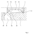
- Fig. 2 das Detail betreffend den Steuerbolzen und die Steuerkurve entsprechend Fig. 1 in vergrößerter Darstellung.
- 1 is an axial section through a chuck according to the invention,
- Fig. 2 shows the detail regarding the control pin and the control cam corresponding to FIG. 1 in an enlarged view.
Das in der Zeichnung dargestellte Spannfutter besitzt einen Futterkörper 1, der über eine Ausdrehung 2 mit Hilfe von Schrauben 3 an der Stirnseite einer nicht dargestellten Drehmaschinenspindel befestigt werden kann.The chuck shown in the drawing has a
Im Futterkörper 1 sind radial Spannbacken 4 geführt, von welchen in der Zeichnung nur eine dargestellt ist. Zur radialen Verstellung der Spannbacken 4 ist ein im Futterkörper 1 axial verstellbares Antriebsglied 5 vorgesehen. Im Ausführungsbeispiel steht das Antriebsglied 5 über eine Keilhakenverbindung mit den Spannbacken 4 im Eingriff, wobei der Keilhaken 6 fest am Antriebsglied 5, der Keilhaken 7 fest am der Spannbacke 4 sitzt. In der Zeichnung ist das Antriebsglied 5 in seiner rechten Endstellung gezeigt. Dies entspricht der äußeren radialen Endstellung der Spannbacken 4, also bei Außenspannung des nicht dargestellten Werdstücks dem offenen Zustand des Spannfutters. Wird das Antriebsglied 5 in der Zeichnung nach links bewegt, verstellen sich die Spannbacken 4 radial nach innen und spannen das Werkstück ein. Der Spannhub des Antriebsgliedes 5 ist also in der Zeichnung nach links gerichtet. Statt der Keilhakenverbindung zwischen den Spannbacken 4 und dem Antriebsglied 5 können auch andere geeignete Antriebsverbindungen Verwendung finden.Radially clamping jaws 4 are guided in the
Zur Verstellung des Antriebsgliedes 5 dient ein im Ausführungsbeispiel unmittelbar in einem Ringzylinderraum 8a, 8b des Futterkörpers 1 verschiebbarer Spannkolben 9, der durch Schrauben 10 fest mit dem Antriebsglied 5 verbunden ist. Zur Beaufschlagung des Spannkolbens 9 mit Druckmittel ist außen auf dem Futterkörper 1 drehbar ein Anschlußring 11 gelagert, der Anschlußöffnungen 11′ für die Zu- und Abfuhr des Druckmittels aufweist. Gelangt das Druckmittel in den auf der rechten Seite des Spannkolbens 9 befindlichen Zylinderraum 8b so erfolgt der Spannhub, im anderen Fall der Lösehub. Die Verhältnisse drehen sich entsprechend um, wenn statt der angenommen Außenspannung eine Innenspannung erfolgen soll, der Spannhub der Spannbacken 4 also radial nach außen gerichtet ist.A tensioning piston 9, which in the exemplary embodiment can be moved directly in an
Zur Überwachung des Spannvorgangs ist eine auf den Drehantrieb der nicht dargestellten Maschine einwirkende Funktionskontrolleinrichtung vorgesehen. Sie umfaßt einen außerhalb des Spannfutters feststehenden Sensor 18, ein den Sensor betätigendes, am Außenumfang des Futterkörpers verstellbar angeordnetes Schaltglied 17 und einen das Schaltglied verstellenden Kontrollkolben 12, der gegen die Kraft einer Rückstellfeder 13 vom Druckmittel des Spannkolbens 9 beaufschlagt ist, wozu zwischen den Zylinderräumen 8a, 8b des Spannkolbens 9 und dem Zylinderraum 14 des Kontrollkolbens 12 geeignete, in der Zeichnung lediglich bei 15 erkennbare Verbindungskanäle bestehen. Der Kontrollkolben 12 ist gegen vom Druckmittel bewirkte Verschiebungen in einer den Drehantrieb ausschaltenden Sperrstellung verriegelt oder in diese Sperrstellung verstellbar, wenn das Antriebsglied 5 in zwei in der Zeichnung durch die Doppelpfeile 16 angedeuteten Sicherheitsbereichen an den Enden seines axialen Hubweges steht. Der dem Arbeitsbereich des Antriebsgliedes 5 entsprechende Teil des axialen Hubweges ist durch den Doppelpfeil 16′ gekennzeichnet. Der Kontrollkolben 12 ist parallel zur Futterachse verschiebbar angeordnet und über ein Keilgetriebe 19 mit einem radial zur Futterachse verschiebbar im Futterkörper1 geführten Steuerbolzen 20 gekuppelt. Diesem Steuerbolzen 20 ist eine mit dem Antriebsglied 5 bewegte Steuerkurve 21 zugeordnet, die als Anschlag zur Begrenzung des radial einwärts gerichteten Verschiebungswegs des Steuerbolzens 20 wirkt. Das Keilgetriebe 19 ist dabei so ausgebildet, daß eine Verschiebung des Kontrollkolbens 12 aus seiner Sperrstellung mit einer radial einwärts gerichteten Verschiebung des Steuerbolzens 20 verbunden ist. Der Kontrollkolben 12 und der Steuerbolzen 20 sind durch das Keilgetriebe aneinander zwangsgeführt, so daß die Stellungen des Kontrollkolbens 12 und des Steuerbolzens 20 eindeutig einander zugeordnet sind. Dazu besteht das Keilgetriebe 19 aus einem zu den Achsen von Kontrollkolben 12 und Steuerbolzen 20 geneigt angeordneten Keilsteg 19.1 und einer ihn aufnehmenden Keilnut 19.2, die in der Zeichnung lediglich gestrichelt angedeutet sind, da sich je nach Zweckmäßigkeit der Keilsteg 19.1 wahlweise am Kontrollkolben 12 oder am Steuerbolzen 20 und dementsprechend die Keilnut 19.2 am Steuerbolzen 20 bzw. Kontrollkolben 12 befinden kann. Am Kontrollkolben 12 ist axial formschlüssig eine im Futterkörper 1 axial verschiebbare Steuerstange 22 angeschlossen, durch die das Schaltglied 17 axial mit dem Kontrollkolben 12 verbunden und verstellbar ist. Das Schaltglied 17 ist ein über die Mantelfläche des Futterkörpers 1 radial abstehender schaltnocken, der in einer Axialnut 23 des Futterkörpers geführt ist und durch einen Schlitz 24 im Nutboden hindurch mit der Steuerstange 22 mittels einer Schraube 25 in Verbindung steht. Der Sensor 18 ist im Ausführungsbeispiel als induktiver Näherungsschalter ausgebildet, der vom Schaltglied 17 berührungslos gesteuert wird.A function control device acting on the rotary drive of the machine, not shown, is provided for monitoring the clamping process. It comprises a
Der im vorderen Teil des Futterkörpers 1 angeordnete Kontrollkolben 12 besitzt einen axial aus der vorderen Stirnseite 1′ des Futterkörpers 1 vorstehenden Kolbenhals 26, in dem sich eine von der Stirnseite 1′ her zugängliche Einstellschraube 27 befindet, mit der die Kraft der Rückstellfeder 13 einstellbar ist. Die Rückstellfeder 13 liegt in einer Längsbohrung 28 des Kontrollkolbens 12, in der sich die Rückstellfeder 13 in Form einer Schraubenfeder über ein in der Längsbohrung 28 verschiebbares Widerlager 29 gegen die Einstellschraube 13 abstützt. Das andere, aus der Längsbohrung 28 herausragende Ende der Rückstellfeder 13 stützt sich am Futterkörper 1 ab, wozu der Futterkörper 1 mit einer das Federende zentrierenden Aufnahme 30 versehen ist. Im einzelnen ist der mit Druckmittel beaufschlagbare Zylinderraum 14 des Kontrollkolbens 12 durch eine im Futterkörper 1 zu dessen Stirnseite 1′ hin offene Bohrung gebildet, die stirnseitig durch einen Zylinderdeckel 31 verschlossen ist, durch den hindurch abgedichtet der Kolbenhals 26 geführt ist. Der Zylinderdeckel 31 ist bündig mit der Stirnseite 1′ des Futterkörpers 1.The arranged in the front part of the
Die Rückstellfeder 13 beaufschlagt den Kontrollkolben 12 axial nach vorn und den Steuerbolzen 20 über das Keilgetriebe 19 radial auswärts. In der Zeichnung befindet sich der Kontrollkolben 12 in der vorderen Endstellung, die seiner Sperrstellung entspricht. Aus dieser Sperrstellung kann sich der Kontrollkolben 12 unter der Wirkung des Druckmittels nur in der Zeichnung nach links bewegen und über die Steuerstange 22 und das Schaltglied 17 sowie den Sensor 18 den Drehantrieb der Maschine freigeben, wenn über das Keilgetriebe 19 der Steuerbolzen 20 entsprechend radial einwärts verstellbar ist, also an dieser Verstellung nicht durch Anschlag an der Steuerkurve 21 gehindert wird. Daher ist die Steuerkurve 21 im Bereich beider axialer Kurvenenden mit radial auswärts gerichteten Steuervorsprüngen 21.1 versehen, deren axiale Länge jeweils den Sicherheitsbereichen 16 des axialen Hubwegs des Antriebsglieds 5 entspricht. Diese Steuervorsprünge 21.1 schließen über Anlaufschrägen 21.2 an den dem Arbeitsbereich 16′ des Antriebsgliedes 5 entsprechenden Teil 21.3 der Steuerkurve an. Entsprechende Anlaufschrägen 20.1 sind an dem der Steuerkurve 21 anliegenden Kopf 20.2 des Steuerbolzens 20 vorgesehen, so daß bei Verstellung des Antriebsglieds 5 aus dem Arbeitsbereich 16′ in einen der beiden Sicherheitsbereiche 16 der Steuerbolzen 20 über diese Anlaufschrägen radial nach außen und damit der Kontrollkolben 12 über das Keilgetriebe 19 axial nach vorn gegen die Kraft des Druckmittels in die Sperrstellung gedrückt wird. Im einzelnen ist die Steuerkurve 21 durch den Boden einer axial am Antriebsglied 5 verlaufenden Steuernut 21.4 gebildet, in die der Steuerbolzen 20 mit seinem die Anlaufschrägen 20.1 tragenden Bolzenkopf 20.2 eingreift.The
Im Ergebnis bewirkt die Funktionskontrolleinrichtung die Überprüfung von zwei Voraussetzungen für das wirksame Einspannen eines Werkstückes, ob sich nämlich das Spannglied 5 wirklich im Arbeitsbereich befindet, also die Sicherheitsbereiche 16 verlassen hat, und ob der Spanndruck ausreichende Größe besitzt. Insoweit setzt die Freigabe des Drehantriebs, also die Verstellung des Kontrollkolbens 12 in der Zeichnung nach links, voraus, daß die vom Druckmittel auf den Kontrollkolben 12 ausgeübte Kraft die entgegen gerichtete Kraft der Rückstellfeder 13 übersteigt. Die Kraft der Rückstellfeder 13 entspricht also einem dem Futter zugeordneten Mindestspanndruck. Die Größe dieses Mindestspanndrucks kann durch Einstellen der Kraft der Rückstellfeder 13 entsprechend gewählt werden. Die Kontrolle erfolgt bei rotierendem und stillstehendem Spannfutter, wobei das Futter im letzteren Fall lediglich so zu positionieren ist, daß das Schaltglied 17 dem Sensor 18 gegenübersteht. - Sind beide Voraussetzungen erfüllt, befindet sich der Kontrollkolben 12 und damit auch das Schaltglied 17 in ihrer axial rückwärtigen Endstellung, in der der Sensor 18 nicht aktiviert ist. Der Drehantrieb der Maschine ist freigegeben. Ist jedoch nur eine der beiden Voraussetzungen erfüllt, bleiben der Kontrollkolben 12 und das Schaltglied 17 in ihrer in der Zeichnung dargestellten vorderen Endstellung, wobei der Sensor 18 aktiviert ist und den Stillstand der Maschine bewirkt. Diese Arbeitsweise der Funktionskontrolleinrichtung sei noch an einigen Fehlerbeispielen weiter erläutert:
Ist der Betriebsdruck zu niedrig, befindet sich aber das Antriebsglied 5 in Arbeitsstellung, so verhindert doch die auf den Mindestdruck eingestellte Kraft der Rückstellfeder 13 ein Verschieben des Kontrollkolbens 12 aus der Sperrstellung.
Ist der Betriebsdruck ausreichend, hat aber das Antriebsglied 5 den Sicherheitsbereich 16 nicht verlassen, so kann der Steuerbolzen 20 nicht radial einwärts ausweichen und der Kontrollkolben 12 bleibt wiederum in seiner Sperrstellung stehen.
Ist der Betriebsdruck ausreichend, hat aber das Antriebsglied 5 den Arbeitsbereich 16′ durchfahren und befindet sich im nachfolgenden Sicherheitsbereich 16, so kann der Kontrollkolben 12 zwar kurzzeitig aus der Sperrstellung axial nach hinten herausfahren, wird jedoch sofort anschließend zwangsweise über die Steuerkurve 21 des Antriebsglieds 5 und den Steuerbolzen 20 wieder nach vorn in die Sperrstellung gedrückt.
Fällt der Betriebsdruck während der Rotation des Spannfutters ab, so bewirkt die Kraft der Rückstellfeder 13 beim Unterschreiten des Mindestdrucks das Vorfahren des Kontrollkolbens 12 in die Sperrstellung.As a result, the function control device checks two prerequisites for the effective clamping of a workpiece, namely whether the clamping
If the operating pressure is too low, but the
If the operating pressure is sufficient, but the
If the operating pressure is sufficient, but the
If the operating pressure drops during the rotation of the chuck, the force of the
Claims (11)
Applications Claiming Priority (2)
| Application Number | Priority Date | Filing Date | Title |
|---|---|---|---|
| DE3725714 | 1987-08-04 | ||
| DE3725714A DE3725714C1 (en) | 1987-08-04 | 1987-08-04 |
Publications (2)
| Publication Number | Publication Date |
|---|---|
| EP0302187A1 true EP0302187A1 (en) | 1989-02-08 |
| EP0302187B1 EP0302187B1 (en) | 1990-10-17 |
Family
ID=6332963
Family Applications (1)
| Application Number | Title | Priority Date | Filing Date |
|---|---|---|---|
| EP88107289A Expired - Lifetime EP0302187B1 (en) | 1987-08-04 | 1988-05-06 | Chucking fixture on laths |
Country Status (5)
| Country | Link |
|---|---|
| US (1) | US4932674A (en) |
| EP (1) | EP0302187B1 (en) |
| JP (1) | JPH0659564B2 (en) |
| DE (1) | DE3725714C1 (en) |
| ES (1) | ES2018863B3 (en) |
Families Citing this family (10)
| Publication number | Priority date | Publication date | Assignee | Title |
|---|---|---|---|---|
| US6257595B1 (en) | 1998-09-04 | 2001-07-10 | Hardinge Inc. | Collect chuck with quick-change cap |
| US6202523B1 (en) | 1998-11-10 | 2001-03-20 | J. F. Berns Co., Inc. | Air operated loading and unloading device |
| DE10163104A1 (en) * | 2001-12-20 | 2003-07-03 | Roemheld A Gmbh & Co Kg | Zentrierspannelement |
| DE10207567A1 (en) * | 2002-02-22 | 2003-09-04 | Roehm Gmbh | A ball pin chuck |
| DE10307565A1 (en) * | 2002-10-09 | 2004-04-22 | Smw-Autoblok Spannsysteme Gmbh | Heavy duty chuck or similar has pressure sensor for monitoring pressure in pressure chambers associated with one or both pistons, receiver connected to unit for evaluating pressure sensor signals |
| US7513181B2 (en) * | 2003-11-24 | 2009-04-07 | J.F. Berns Co., Inc. | Air operated unloading device |
| FR2883359B1 (en) * | 2005-03-15 | 2007-05-11 | Valeo Vision Sa | LUMINOUS PROJECTOR FOR A MOTOR VEHICLE WITH LOW DIMENSIONS |
| CN102581328B (en) * | 2012-03-14 | 2013-12-04 | 赵长军 | Front swinging cylinder-type hollow hydraulic chuck |
| CN103769639B (en) * | 2014-02-14 | 2015-07-29 | 哈尔滨工业大学 | With bidirectionally limited external clamping type electric precise chuck |
| CN103785873B (en) * | 2014-02-14 | 2015-07-29 | 哈尔滨工业大学 | Precise pneumatic chuck |
Citations (3)
| Publication number | Priority date | Publication date | Assignee | Title |
|---|---|---|---|---|
| DE3102099A1 (en) * | 1981-01-23 | 1982-08-19 | Röhm GmbH, 7927 Sontheim | CLAMPING DEVICE ON LATHE WITH A CHUCK |
| DE3518332C1 (en) * | 1985-05-22 | 1986-05-22 | Paul Forkardt GmbH & Co KG, 4000 Düsseldorf | Rotating power-operated chuck, in particular for lathes |
| DE3228749C2 (en) * | 1982-07-31 | 1986-10-16 | Paul Forkardt GmbH & Co KG, 4000 Düsseldorf | Device for determining the working range of a double-acting clamping cylinder for actuating clamping devices on machine tools, in particular exchangeable chucks on lathes |
Family Cites Families (3)
| Publication number | Priority date | Publication date | Assignee | Title |
|---|---|---|---|---|
| DE2924111C2 (en) * | 1979-06-15 | 1986-07-17 | SMW Schneider & Weißhaupt GmbH, 7996 Meckenbeuren | Device for monitoring the pressure in pressurized fluid-operated chucks with clamping cylinders rotating during operation on processing machines |
| DE3402988A1 (en) * | 1984-01-28 | 1985-08-08 | SMW Schneider & Weißhaupt GmbH, 7996 Meckenbeuren | DEVICE FOR MONITORING THE OPERATING CONDITION OF A POWER CHUCK |
| DE3402989A1 (en) * | 1984-01-28 | 1985-08-08 | SMW Schneider & Weißhaupt GmbH, 7996 Meckenbeuren | DEVICE FOR MONITORING THE OPERATING CONDITION OF A POWER CHUCK |
-
1987
- 1987-08-04 DE DE3725714A patent/DE3725714C1/de not_active Expired
-
1988
- 1988-05-06 EP EP88107289A patent/EP0302187B1/en not_active Expired - Lifetime
- 1988-05-06 ES ES88107289T patent/ES2018863B3/en not_active Expired - Lifetime
- 1988-08-02 JP JP63194311A patent/JPH0659564B2/en not_active Expired - Fee Related
- 1988-08-04 US US07/228,904 patent/US4932674A/en not_active Expired - Lifetime
Patent Citations (3)
| Publication number | Priority date | Publication date | Assignee | Title |
|---|---|---|---|---|
| DE3102099A1 (en) * | 1981-01-23 | 1982-08-19 | Röhm GmbH, 7927 Sontheim | CLAMPING DEVICE ON LATHE WITH A CHUCK |
| DE3228749C2 (en) * | 1982-07-31 | 1986-10-16 | Paul Forkardt GmbH & Co KG, 4000 Düsseldorf | Device for determining the working range of a double-acting clamping cylinder for actuating clamping devices on machine tools, in particular exchangeable chucks on lathes |
| DE3518332C1 (en) * | 1985-05-22 | 1986-05-22 | Paul Forkardt GmbH & Co KG, 4000 Düsseldorf | Rotating power-operated chuck, in particular for lathes |
Also Published As
| Publication number | Publication date |
|---|---|
| DE3725714C1 (en) | 1988-06-23 |
| JPH0659564B2 (en) | 1994-08-10 |
| ES2018863B3 (en) | 1991-05-16 |
| EP0302187B1 (en) | 1990-10-17 |
| US4932674A (en) | 1990-06-12 |
| JPS6451210A (en) | 1989-02-27 |
Similar Documents
| Publication | Publication Date | Title |
|---|---|---|
| DE4313742C1 (en) | Chuck mechanism for drill - has stop device for tension ring, comprising crown of stop recesses, and stop component which presses into recesses under force of stop spring | |
| DE2711904C3 (en) | Chuck for lathes | |
| EP2370222B1 (en) | Tool holder | |
| EP0620068B1 (en) | Drilling chuck | |
| EP0677348A1 (en) | Chuck | |
| EP0151791B1 (en) | Chuc in particular drill chuck | |
| EP0258771A2 (en) | Chuck | |
| EP0125434A2 (en) | Machine tool with a tool changing device | |
| DE2533803B2 (en) | Power operated wedge chuck | |
| EP0302187B1 (en) | Chucking fixture on laths | |
| EP0008318A1 (en) | Chuck for turning machines | |
| EP1572403B1 (en) | Clamping chuck and key rod therefor | |
| EP0005458B1 (en) | Chuck for turning machines | |
| EP0175065A1 (en) | Adjustable drill chuck | |
| DE3709299C2 (en) | ||
| DE2736753A1 (en) | Lathe chuck with detachable jaws - has cam and wedge mechanism with toothed rack to lock jaw in position | |
| DE3323709C2 (en) | Tapping chuck | |
| DE2648997A1 (en) | Machine tool chuck with independent jaws - has jaws tightened inwardly by collet action once separate positions have been set | |
| DE2817368C2 (en) | Chuck for lathes | |
| WO2005028148A1 (en) | Interface of a tool | |
| DE3438145C1 (en) | Drill chucks, especially hammer drill chucks | |
| DE3425609A1 (en) | Clamping chuck | |
| DE2937194A1 (en) | Locking device for lathe chuck - has locking key which can only be removed if lock is fully engaged | |
| DE2916179A1 (en) | TENSIONING DEVICE, IN PARTICULAR MACHINE VICE | |
| DE1602755C3 (en) | Drill head with a spindle shank |
Legal Events
| Date | Code | Title | Description |
|---|---|---|---|
| PUAI | Public reference made under article 153(3) epc to a published international application that has entered the european phase |
Free format text: ORIGINAL CODE: 0009012 |
|
| AK | Designated contracting states |
Kind code of ref document: A1 Designated state(s): ES FR GB IT SE |
|
| 17P | Request for examination filed |
Effective date: 19890124 |
|
| 17Q | First examination report despatched |
Effective date: 19900404 |
|
| GRAA | (expected) grant |
Free format text: ORIGINAL CODE: 0009210 |
|
| AK | Designated contracting states |
Kind code of ref document: B1 Designated state(s): ES FR GB IT SE |
|
| ITF | It: translation for a ep patent filed |
Owner name: STUDIO JAUMANN |
|
| ET | Fr: translation filed | ||
| GBT | Gb: translation of ep patent filed (gb section 77(6)(a)/1977) | ||
| PLBE | No opposition filed within time limit |
Free format text: ORIGINAL CODE: 0009261 |
|
| STAA | Information on the status of an ep patent application or granted ep patent |
Free format text: STATUS: NO OPPOSITION FILED WITHIN TIME LIMIT |
|
| 26N | No opposition filed | ||
| ITTA | It: last paid annual fee | ||
| EAL | Se: european patent in force in sweden |
Ref document number: 88107289.6 |
|
| PGFP | Annual fee paid to national office [announced via postgrant information from national office to epo] |
Ref country code: SE Payment date: 19950405 Year of fee payment: 8 |
|
| PGFP | Annual fee paid to national office [announced via postgrant information from national office to epo] |
Ref country code: ES Payment date: 19950424 Year of fee payment: 8 |
|
| PGFP | Annual fee paid to national office [announced via postgrant information from national office to epo] |
Ref country code: FR Payment date: 19950510 Year of fee payment: 8 |
|
| PG25 | Lapsed in a contracting state [announced via postgrant information from national office to epo] |
Ref country code: SE Effective date: 19960507 Ref country code: ES Free format text: LAPSE BECAUSE OF NON-PAYMENT OF DUE FEES Effective date: 19960507 |
|
| PG25 | Lapsed in a contracting state [announced via postgrant information from national office to epo] |
Ref country code: FR Effective date: 19970131 |
|
| EUG | Se: european patent has lapsed |
Ref document number: 88107289.6 |
|
| REG | Reference to a national code |
Ref country code: FR Ref legal event code: ST |
|
| REG | Reference to a national code |
Ref country code: ES Ref legal event code: FD2A Effective date: 19990405 |
|
| PGFP | Annual fee paid to national office [announced via postgrant information from national office to epo] |
Ref country code: GB Payment date: 20000425 Year of fee payment: 13 |
|
| PG25 | Lapsed in a contracting state [announced via postgrant information from national office to epo] |
Ref country code: GB Free format text: LAPSE BECAUSE OF NON-PAYMENT OF DUE FEES Effective date: 20010506 |
|
| GBPC | Gb: european patent ceased through non-payment of renewal fee |
Effective date: 20010506 |
|
| PG25 | Lapsed in a contracting state [announced via postgrant information from national office to epo] |
Ref country code: IT Free format text: LAPSE BECAUSE OF NON-PAYMENT OF DUE FEES Effective date: 20050506 |