EP0302003B1 - Process for the production of specimen for the ultrasonic purity degree determination of continuously cast steel - Google Patents
Process for the production of specimen for the ultrasonic purity degree determination of continuously cast steel Download PDFInfo
- Publication number
- EP0302003B1 EP0302003B1 EP88730154A EP88730154A EP0302003B1 EP 0302003 B1 EP0302003 B1 EP 0302003B1 EP 88730154 A EP88730154 A EP 88730154A EP 88730154 A EP88730154 A EP 88730154A EP 0302003 B1 EP0302003 B1 EP 0302003B1
- Authority
- EP
- European Patent Office
- Prior art keywords
- specimen
- rolling
- thickness
- casting
- thickness dimension
- Prior art date
- Legal status (The legal status is an assumption and is not a legal conclusion. Google has not performed a legal analysis and makes no representation as to the accuracy of the status listed.)
- Expired - Lifetime
Links
- 238000000034 method Methods 0.000 title claims description 17
- 238000004519 manufacturing process Methods 0.000 title description 6
- 229910001208 Crucible steel Inorganic materials 0.000 title 1
- 238000005096 rolling process Methods 0.000 claims description 24
- 238000012360 testing method Methods 0.000 claims description 15
- 238000005266 casting Methods 0.000 claims description 14
- 229910000831 Steel Inorganic materials 0.000 claims description 9
- 239000010959 steel Substances 0.000 claims description 9
- 239000002184 metal Substances 0.000 claims description 8
- 229910052751 metal Inorganic materials 0.000 claims description 8
- 238000009749 continuous casting Methods 0.000 claims description 7
- 238000002604 ultrasonography Methods 0.000 claims description 7
- 239000012535 impurity Substances 0.000 claims description 4
- 238000011835 investigation Methods 0.000 claims description 3
- 230000015572 biosynthetic process Effects 0.000 claims 1
- 238000000926 separation method Methods 0.000 claims 1
- 239000000463 material Substances 0.000 description 7
- XEEYBQQBJWHFJM-UHFFFAOYSA-N Iron Chemical compound [Fe] XEEYBQQBJWHFJM-UHFFFAOYSA-N 0.000 description 4
- 230000006835 compression Effects 0.000 description 3
- 238000007906 compression Methods 0.000 description 3
- 238000011161 development Methods 0.000 description 3
- 230000018109 developmental process Effects 0.000 description 3
- 238000010998 test method Methods 0.000 description 3
- 235000015241 bacon Nutrition 0.000 description 2
- 229910052742 iron Inorganic materials 0.000 description 2
- 238000005088 metallography Methods 0.000 description 2
- 150000002739 metals Chemical class 0.000 description 2
- 229910000640 Fe alloy Inorganic materials 0.000 description 1
- CWYNVVGOOAEACU-UHFFFAOYSA-N Fe2+ Chemical compound [Fe+2] CWYNVVGOOAEACU-UHFFFAOYSA-N 0.000 description 1
- 241000209035 Ilex Species 0.000 description 1
- NINIDFKCEFEMDL-UHFFFAOYSA-N Sulfur Chemical compound [S] NINIDFKCEFEMDL-UHFFFAOYSA-N 0.000 description 1
- 238000009825 accumulation Methods 0.000 description 1
- 229910045601 alloy Inorganic materials 0.000 description 1
- 239000000956 alloy Substances 0.000 description 1
- 238000012550 audit Methods 0.000 description 1
- 239000000356 contaminant Substances 0.000 description 1
- 230000001419 dependent effect Effects 0.000 description 1
- 238000009826 distribution Methods 0.000 description 1
- 230000009189 diving Effects 0.000 description 1
- 230000000694 effects Effects 0.000 description 1
- 238000000605 extraction Methods 0.000 description 1
- -1 ferrous metals Chemical class 0.000 description 1
- 238000007689 inspection Methods 0.000 description 1
- 238000009434 installation Methods 0.000 description 1
- 238000002955 isolation Methods 0.000 description 1
- 239000002245 particle Substances 0.000 description 1
- 238000005554 pickling Methods 0.000 description 1
- 239000002994 raw material Substances 0.000 description 1
- 230000000717 retained effect Effects 0.000 description 1
- 239000002893 slag Substances 0.000 description 1
- 238000001228 spectrum Methods 0.000 description 1
- 229910052717 sulfur Inorganic materials 0.000 description 1
- 239000011593 sulfur Substances 0.000 description 1
Images


Classifications
-
- G—PHYSICS
- G01—MEASURING; TESTING
- G01N—INVESTIGATING OR ANALYSING MATERIALS BY DETERMINING THEIR CHEMICAL OR PHYSICAL PROPERTIES
- G01N1/00—Sampling; Preparing specimens for investigation
- G01N1/02—Devices for withdrawing samples
- G01N1/04—Devices for withdrawing samples in the solid state, e.g. by cutting
-
- G—PHYSICS
- G01—MEASURING; TESTING
- G01N—INVESTIGATING OR ANALYSING MATERIALS BY DETERMINING THEIR CHEMICAL OR PHYSICAL PROPERTIES
- G01N1/00—Sampling; Preparing specimens for investigation
- G01N1/28—Preparing specimens for investigation including physical details of (bio-)chemical methods covered elsewhere, e.g. G01N33/50, C12Q
-
- G—PHYSICS
- G01—MEASURING; TESTING
- G01N—INVESTIGATING OR ANALYSING MATERIALS BY DETERMINING THEIR CHEMICAL OR PHYSICAL PROPERTIES
- G01N29/00—Investigating or analysing materials by the use of ultrasonic, sonic or infrasonic waves; Visualisation of the interior of objects by transmitting ultrasonic or sonic waves through the object
- G01N29/04—Analysing solids
- G01N29/048—Marking the faulty objects
-
- G—PHYSICS
- G01—MEASURING; TESTING
- G01N—INVESTIGATING OR ANALYSING MATERIALS BY DETERMINING THEIR CHEMICAL OR PHYSICAL PROPERTIES
- G01N33/00—Investigating or analysing materials by specific methods not covered by groups G01N1/00 - G01N31/00
- G01N33/20—Metals
- G01N33/202—Constituents thereof
- G01N33/2022—Non-metallic constituents
Definitions
- the core idea of the invention is a concentration of the inclusions or impurities in certain areas, so that a statement about the degree of purity of a product, in particular the continuous casting material itself, can be made from the accumulation encountered there.
- the invention is based on fundamental investigations of the position of the inclusion band in arch strands.
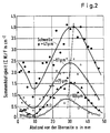
- Figure 2 shows the size spectrum of the inclusions on the top of a contaminated 177 mm round strand.
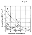
- FIG. 3 shows the clean underside of the same strand.
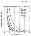
- Figure 4 Distribution of length of the stretched inclusions shows that the inclusions of originally spherical shape are stretched more with increasing rolling temperature.
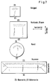
- FIG. 7 schematically shows the position of the inclusion band in the case of billets, blooms and slabs on forges perpendicular to the casting direction.
- Suitable blocks can be sawn out of the cast product, although a 10-fold reduction in thickness is necessary to sensitize the inclusions.
- the test sheet must not be thinner than 10 mm, because the ultrasound is the first millimeter thickness of a test sheet, i.e. the area near the surface is not covered. There is no general limit to the starting thickness of the billet, but it can depend on the local rolling possibilities.
- the invention can be used to orient continuous cast material of unknown origin with respect to the top and bottom of the casting and to examine the degree of purity of the material.
- a raw material supplier may produce a strand in the format 360 mm x 420 mm produced by the sheet continuous casting process and roll it into 177 mm tubular round material. Pickling disc and S-trigger do not provide any information.
- the 177 mm round material is randomly notched in two places on the jacket (and rolled into a surfboard).
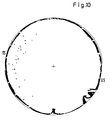
- Figure 9 shows the US test result.
- the ellipse is mathematically transformed back to the round material, see Figure 10. Now the direction of the top and bottom of the casting is determined. With the knowledge of the orientation, further 177 mm round samples can be examined specifically for the degree of purity. In this way, you can also distinguish block casting from arch casting afterwards, which is usually very difficult after pre-forming.
- the invention is also applicable to "thin-walled” products such as Pipes or sheets or also on cross sections, e.g. less than 100 mm in diameter or edge length, which due to their slenderness cannot be squeezed in the longitudinal direction of the sample (buckling of the sample under pressure).
Landscapes
- Health & Medical Sciences (AREA)
- Life Sciences & Earth Sciences (AREA)
- Chemical & Material Sciences (AREA)
- Physics & Mathematics (AREA)
- Immunology (AREA)
- Biochemistry (AREA)
- General Health & Medical Sciences (AREA)
- General Physics & Mathematics (AREA)
- Analytical Chemistry (AREA)
- Pathology (AREA)
- Engineering & Computer Science (AREA)
- Food Science & Technology (AREA)
- Medicinal Chemistry (AREA)
- Acoustics & Sound (AREA)
- Sampling And Sample Adjustment (AREA)
- Investigating Or Analyzing Materials By The Use Of Ultrasonic Waves (AREA)
Description
Die Erfindung betrifft ein Verfahren zur Herstellung von Proben für die Reinheitsgradbestimmung von Metallen.The invention relates to a method for producing samples for determining the degree of purity of metals.
Unter Metallen werden Eisen- und Nichteisenmetalle sowie deren Legierungen verstanden, die infolge ihres metallurgischen Herstellungsprozesses nicht gewünschte Verunreinigungen enthalten. Diese Verunreinigungen bestehen im wesentlichen aus nichtmetallischen Phasen, die temperaturabhängig verformbar sind. Durch eine Untersuchung mittels Ultraschall und entsprechender Anzeige kann der im Metall entahltene Anteil erkannt und ausgewertet werden. Diese Untersuchungen werden im Rahmen der Reinheitsgradbestimmungen durchgeführt. Im Bereich der Eisenlegierungen findet die Erfindung vorzugsweise Anwendung bei Stählen, die im Stranggußverfahren vergossen wurden.Metals are understood to mean ferrous and non-ferrous metals and their alloys, which contain undesirable impurities due to their metallurgical manufacturing process. These contaminants essentially consist of non-metallic phases that can be deformed depending on the temperature. The portion removed from the metal can be identified and evaluated by means of an ultrasound examination and a corresponding display. These examinations are carried out as part of the purity level determination. In the field of iron alloys, the invention is preferably used for steels which have been cast using the continuous casting process.
Mit steigenden Anforderungen an das Produkt wird die Bestimmung des Reinheitsgrades problematischer. Standardisierte Prüfmethoden büßen zunehmend an Aussagekraft ein. Mehr und mehr wird die Ausfallrate am Produkt - bei der Fertigung oder im Gebrauch - als Kennwert für den Reinheitsgrad herangezogen. Für die Stahlherstellung und metallurgische Entwicklungen ist diese Situation unbefriedigend, weil keine Rückkoppelung zum Verbraucher besteht oder die Information viel zu spät kommt. Weltweit besteht deshalb ein Bedarf an neuen Methoden, die rationell, schnell, kostengünstig, zuverlässig, quantifizierbar und differenzierend auf einzelne Abschnitte eines Erzeugnisses, insbesondere Strangabschnitte, anwendbar sind. Mit der hier geschilderten neuen Methode wird dieses Ziel erreicht.With increasing demands on the product, the determination of the degree of purity becomes more problematic. Standardized test methods are increasingly losing relevance. The failure rate on the product - during manufacture or in use - is increasingly being used as a parameter for the degree of purity. This situation is unsatisfactory for steel production and metallurgical developments because there is no feedback to the consumer or the information is much too late. There is therefore a worldwide need for new methods which can be used rationally, quickly, inexpensively, reliably, quantifiable and differentiating for individual sections of a product, in particular strand sections. This goal is achieved with the new method described here.
- Schwefelabzug (Baumannabdruck)Sulfur deduction (Baumann imprint)
- Metallografie nach Stahleisenprüfblatt 1570Metallography according to steel iron test sheet 1570
- Stufendrehprobe nach Stahleisenprüfblatt 1580Step turning test according to steel iron test sheet 1580
- BlaubruchprobenBlue break samples
- Ultraschall am Grobblech, Ganztafel oder RandzonenprüfungUltrasound on heavy plate, whole board or edge zone inspection
- Slime Extraction Methode (Rückstandsisolierung)Slime extraction method (residue isolation)
- Quantitative Metallografie an 200 cm² großen FlächenQuantitative metallography on 200 cm² areas
Eine Kritik dieser Prüfmethoden würde hier den Rahmen sprengen. Aus der Sicht der Reinheitsgradentwicklung werden die bekannten Methoden der Zielsetzung nicht gerecht. Das Fehlen eines geeigneten Instrumentariums ließ seit vielen Jahren praktisch keine Beurteilung über Erfolg oder Mißerfolg von Maßnahmen im Stahlwerk zu.A criticism of these test methods would go beyond the scope here. From the point of view of the level of purity development, the known methods do not do justice to the objective. For many years, the lack of suitable instruments has meant practically no assessment of the success or failure of measures in the steel mill.
Der Erfindung liegt die Aufgabe zugrunde, ein Verfahren zur Herstellung von Proben zu schaffen, mit dem es möglich ist, Ultraschall-Untersuchungen durchzuführen, die eine exakte Reinheitsgradbestimmung bezogen auf das Erzeugnis selbst zulassen.The invention has for its object to provide a method for the production of samples with which it is possible to carry out ultrasound examinations which allow an exact determination of the degree of purity based on the product itself.
Gelöst wird diese Aufgabe mit den im Anspruch 1 angegebenen Merkmalen.
Vorteilhafte Weiterentwicklungen der Erfindung sind in den abhängigen Ansprüchen enthalten.This object is achieved with the features specified in
Advantageous further developments of the invention are contained in the dependent claims.
Kerngedanke der Erfindung ist eine Konzentrierung der Einschlüsse bzw. Verunreinigungen in bestimmten Bereichen, so daß aus der dort angetroffenen Anhäufung eine Aussage über den Reinheitsgrad eines Erzeugnisses, insbesondere des Stranggußmaterials selbst möglich ist.The core idea of the invention is a concentration of the inclusions or impurities in certain areas, so that a statement about the degree of purity of a product, in particular the continuous casting material itself, can be made from the accumulation encountered there.
Erläutert werden soll dieses Verfahren anhand der Zeichnungen, und zwar der Figuren 1 bis 12.This method is to be explained with the aid of the drawings, specifically FIGS. 1 to 12.
Die Erfindung soll zunächst anhand eines Beispieles, das sich auf einen Rundstrang aus Stahl bezieht, erläutert werden. Hierbei werden alle Einschlüsse 1 einer 25 kg Rundstrangprobe auf ein relativ kleines Ultraschall-Prüfblech konzentriert. Wie in Figur 1 veranschaulicht, wird ein Probenrohling in Form eines Zylinders (Hôhe 120 mm) in ein "Surfbrett" ausgewalzt Bleckducke 12 zum; Dickenreduziezrung zehn fach. Die Walzrichtung ist senkrecht zur Achse des Rundstranges. Von der Unterseite zur Oberseite des Bogenstranges wird gestreckt (fünffach; Walzrichtung II), quer dazu wird gebreitet (zweifach; WR I). Das Einschlußband wird gestaucht. Die hohe Teilchendichte pro Volumeneinheit bleibt erhalten. Im Endeffekt werden die sauberen und schmutzigen Zonen des Stranges für die US-Prüfung säuberlich getrennt. Ballast für die Prüfung wird abgeworfen. Die Einschlüsse werden gestreckt und gebreitet und auf diese Weise für die US-Prüfung sensibilisiert. Trotz einer hinreichenden Umformung sinkt die Dicke der Probe (Blechdicke) nicht unter einen für den Ultraschall kritischen Wert.The invention will first be explained using an example which relates to a round strand made of steel. Here, all
Die Erfindung basiert auf grundlegenden Untersuchungen zur Lage des Einschlußbandes in Bogensträngen.The invention is based on fundamental investigations of the position of the inclusion band in arch strands.
Figur 2 zeigt das Größenspektrum der Einschlüsse auf der Oberseite eines verunreinigten 177-mm- Rundstranges.Figure 2 shows the size spectrum of the inclusions on the top of a contaminated 177 mm round strand.
In Figur 3 ist demgegenüber die saubere Unterseite desselben Stranges dargestellt. Aufgrund von Untersuchungen der Erfinder zur Verformbarkeit der Einschlüsse im Stahl ist für die Ziele der Erfindung eine möglichst hohe Walztemperatur, z.B. 1350 °C, notwendig.In contrast, FIG. 3 shows the clean underside of the same strand. Based on investigations by the inventors on the deformability of the inclusions in the steel, the highest possible rolling temperature, e.g. 1350 ° C, necessary.
Figur 4 Längenversteilung dergestreckten Eindchlüsse zeigt, daß die Einschlüsse von ursprünglich kugeliger Gestalt mit zunehmender Walztemperatur stärker gestreckt werden.Figure 4 Distribution of length of the stretched inclusions shows that the inclusions of originally spherical shape are stretched more with increasing rolling temperature.
In Figur 5 ist ein elliptisch ausgewalzter Einschluß parallel zur Walzebene ausgebildet. Der Einschluß ist zertrümmert, aber die elliptische Kontur ist erkennbar.In Figure 5, an elliptically rolled-out inclusion is formed parallel to the rolling plane. The inclusion is shattered, but the elliptical contour is recognizable.
Figur 6 zeigt einige Beispiele von US-geprüften "Surfbrettproben", die hier in einem Klassensystem geordnet sind.
- Klasse
- Anzeigenhdufigkeit
- 0
- Keine Auzeigen
- 1
- vereinzette Anzeigen:<10 Anzeigen
- 2
- wenige Anzeigen:<20 Anzeigen
- 3
- erkennbares Einschlußband
- 4
- ausgeprägtes Einschlußband
- 5
- sehr dichtes Einschlußband
- 6
- extreme Anzeigendichte, z.B. durch abgenissenen Tauchausguß hervorgerufen.
- great
- Advertising frequency
- 0
- No show
- 1
- single ads: <10 ads
- 2nd
- few ads: <20 ads
- 3rd
- recognizable inclusion band
- 4th
- pronounced inclusion band
- 5
- very dense inclusion band
- 6
- extreme display density, for example caused by a cracked diving spout.
Die Beispiele sind real und metallurgisch begründbar. Als Vergleich sei angemerkt, daß der Baumannabdruck zwischen diesen Fällen nicht differenziert. Im konkreten Fall der Probe mit Klasse 6 war der S-Abzug sogar weiß, weil emulgierte Gießschlacke offenbar vom S-Abzug nicht angezeigt wird.The examples are real and can be justified metallurgically. As a comparison, it should be noted that the Baumannprint does not differentiate between these cases. In the specific case of the sample with
Die Abwicklung des Prüfprogrammes sieht folgendermaßen aus: Rundstrangproben werden planparallel auf 130 mm Länge in Gießrichtung gesägt oder gebrannt. Die Strangoberseite wird anhand der Anpreßbahnen der Stützrollen identifiziert. Dann wird die Unterseite ca. 10 mm tief eingesägt. Der Schlitz dient der Orientierung beim Walzen. Die Rundproben werden auf 1350 °C aufgeheizt. In WR I wird nachfolgendem Stichplan gebreitet: 130 - 120 - 105 - 90 - 80 - 70 - 60 mm. Dann wird die nunmehr elliptische Probe um 90° gedreht und in folgenden Stichen gestreckt (WR II): 48 - 36 - 18 - 13 mm. An der Lage der Kerbe läßt sich ablesen, wie gut symmetrisch gewalzt wurde. Die elliptischen "Surfbretter" werden durch Sägen zerteilt. Auf der Strangeoberseite werden zwei 100 mm breite Streifen vom Scheitel der Ellipse abgetrennt, auf der Unterseite genügt ein Streifen zur Kontrolle, ob nicht eventuell Ober- und Unterseite vor der Walzung verwechselt wurden. Die drei Probenstreifen werden planparallel geschliffen und auf einer HIC-Prüfapparatur geprüft.The execution of the test program looks like this: Round strand samples are sawn or burned plane-parallel over a length of 130 mm in the casting direction. The top of the strand is identified on the basis of the contact tracks of the support rollers. Then the underside is sawn in about 10 mm deep. The slot is used for orientation when rolling. The round samples are heated to 1350 ° C. In WR I, the following pass schedule is shown: 130 - 120 - 105 - 90 - 80 - 70 - 60 mm. Then the now elliptical sample is turned by 90 ° and stretched in the following stitches (WR II): 48 - 36 - 18 - 13 mm. The position of the notch shows how well symmetrical rolling was carried out. The elliptical "surfboards" are cut up by sawing. On the top of the strand, two 100 mm wide strips are separated from the apex of the ellipse, on the underside one strip is enough to check whether the top and bottom have not been mixed up before the rolling. The three sample strips are ground plane-parallel and checked on a HIC test apparatus.
Bei Bogenstranggießanlagen lagern sich die Einschlüsse grundsätzlich im Bereich der Strangoberseite ab. Dies gilt erst recht für den Horizontalstrangguß. Dieses Phänomen ist unabhängig vom Strangformat.
Figur 7 zeigt schematisch die Lage des Einschlußbandes bei Knüppeln, Blooms und Brammen auf Schmitten senkrecht zur Gießrichtung. Durch eine geeignete Walzung von bestimmten Strangabschnitten mit Stauchung des Einschlußbandes kann ein geeignetes Prüfblech erzeugt werden, in dem die Einschlüsse konzentriert und sensibilisiert vorliegen. Die Stauchrichtung kann parallel zur Gießrichtung sein. Sie kann aber auch, bezogen auf die Strangorientierung in der Gießanlage, horizontal sein, d.h. quer zum Gußprodukt. An den Schmalseiten der Bramme kann die Stauchrichtung vertikal sein, obwohl eine solche Walzung, die der herkömmlichen entspräche, nicht den größten Effekt verspricht, sondern allenfalls Resultate wie bei der herkömmlichen Randzonenprüfung.In the case of continuous sheet casting machines, the inclusions are generally deposited in the area of the top of the strand. This is especially true for horizontal continuous casting. This phenomenon is independent of the strand format.
FIG. 7 schematically shows the position of the inclusion band in the case of billets, blooms and slabs on forges perpendicular to the casting direction. By suitable rolling of certain strand sections with compression of the inclusion band, a suitable test sheet can be produced in which the inclusions are concentrated and sensitized. The compression direction can be parallel to the casting direction. However, based on the strand orientation in the casting installation, it can also be horizontal, that is to say transversely to the cast product. To the The narrow side of the slab can be compressed in the vertical direction, although such rolling, which corresponds to the conventional one, does not promise the greatest effect, but at most results as in the conventional edge zone test.
Aus dem Gußprodukt können passende Walzblöcke herausgesägt werden, wobei allerdings eine 10fache Dickenreduzierung zur Sensibilisierung der Einschlüsse notwendig ist. Außerdem darf das Prüfblech nicht dünner als 10 mm werden, weil der Ultraschall die ersten Millimeter Dicke eines Prüfbleches, d.h. den oberflächennahen Bereich nicht erfaßt. In bezug auf die Ausgangsdicke des Walzblockes gibt es keine prinzipielle Grenze, sie kann aber von den örtlichen Walzmöglichkeiten abhängen.Suitable blocks can be sawn out of the cast product, although a 10-fold reduction in thickness is necessary to sensitize the inclusions. In addition, the test sheet must not be thinner than 10 mm, because the ultrasound is the first millimeter thickness of a test sheet, i.e. the area near the surface is not covered. There is no general limit to the starting thickness of the billet, but it can depend on the local rolling possibilities.
In Figur 8 ist für die Rundstränge die horizontale Stauchung des Einschlußbandes durch Walzen parallel und senkrecht zur Gießrichtung erklärt. Vor dem Walzen werden Segmente des Rundquerschnittes abgesägt, damit das Walzgut glatt aufliegt und kontrolliert in den Walzspalt geführt werden kann. Der US-Befund in Figur 8 bestätigt die Anwendbarkeit dieser Art der Walzung. Wenn das vorhergehende Sägen ungenau ist, d.h. nicht im Winkel von 90° zum Einschlußband, dann reichen die US-Anzeigen bis an den Blechrand.In Figure 8, the horizontal compression of the inclusion band is explained by rolling parallel and perpendicular to the casting direction for the round strands. Before rolling, segments of the round cross-section are sawn off so that the rolling stock lies flat and can be guided into the roll gap in a controlled manner. The US finding in Figure 8 confirms the applicability of this type of rolling. If the previous sawing is inaccurate, ie not at an angle of 90 ° to the inclusion band, then the US advertisements extend to the edge of the sheet.
Die Erfindung kann benutzt werden, um stranggegossenes Vormaterial unbekannter Herkunft bezüglich Gießoberseite und -unterseite zu orientieren und den Reinheitsgrad des Materials zu untersuchen. Ein Vormateriallieferant möge einen nach dem Bogenstranggießverfahren hergestellten Strang im Format 360 mm x 420 mm erzeugen und diesen zu 177 mm Röhrenrundmaterial walzen. Beizscheibe und S-Abzug liefern keine Information. Das 177 mm-Rundmaterial wird willkürlich an zwei Stellen des Mantels gekerbt (und zum Surfbrett gewalzt). Figur 9 zeigt das US-Prüfergebnis. Von der Ellipse wird mathematisch auf das Rundmaterial rücktransformiert, s. Figur 10. Jetzt wird die Richtung Gießoberseite-Gießunterseite festgelegt. Weitere 177 mm-Rundproben können mit Kenntnis der Orientierung gezielt auf den Reinheitsgrad untersucht werden. Auf diese Weise kann man auch im Nachhinein Blockguß vom Bogenstrangguß unterscheiden, was nach Vorverformung normalerweise sehr schwierig ist.The invention can be used to orient continuous cast material of unknown origin with respect to the top and bottom of the casting and to examine the degree of purity of the material. A raw material supplier may produce a strand in the format 360 mm x 420 mm produced by the sheet continuous casting process and roll it into 177 mm tubular round material. Pickling disc and S-trigger do not provide any information. The 177 mm round material is randomly notched in two places on the jacket (and rolled into a surfboard). Figure 9 shows the US test result. The ellipse is mathematically transformed back to the round material, see Figure 10. Now the direction of the top and bottom of the casting is determined. With the knowledge of the orientation, further 177 mm round samples can be examined specifically for the degree of purity. In this way, you can also distinguish block casting from arch casting afterwards, which is usually very difficult after pre-forming.
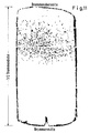
Figur 11 zeigt eine Anwendung der Erfindung auf eine Stranggußbramme. Der S-Abzug hatte keinen übermäßig schlechten Reinheitsgrad angezeigt. Dargestellt ist das US-Ergebnis in der oberen Brammenhälfte. Die untere Hälfte war frei von Anzeigen. Die analysierte Brammenprobe lag bei 1/2 Brammenbreite. In Figur 12 wurde an einer ganz anderen Bramme der Bereich der Schmalseite geprüft. Dort tritt eine Speckschicht auf, die frei von Einschlüssen ist. An beiden gezeigten Brammenproben wurde wie bei der Standardwalzung von Rundmaterial zweifach gebreitet und fünffach gestreckt. Für die genaue Ermittlung der Abstände und Dicken von Speckshicht und Einschlußband müßte vom Blech auf das Gußprodukt rücktransformiert werden. Das ist hier jedoch nicht geschehen. Fig.12 zeigt das Ultraschallergebnis an der gewalzten Brammenprobe (obere Hälfte) aus dem Bereich der Schmalseite.Figure 11 shows an application of the invention to a continuous casting slab. The S trigger had not indicated an excessively poor level of purity. The US result is shown in the upper half of the slab. The bottom half was free of ads. The analyzed slab sample was 1/2 slab width. In Figure 12, the area of the narrow side was checked on a completely different slab. There is a layer of bacon that is free of inclusions. On both of the slab samples shown, as with standard rolling of round material, the sheet was spread twice and stretched five times. For the exact determination of the distances and thicknesses of the bacon layer and inclusion band, the sheet metal would have to be transformed back onto the cast product. However, this did not happen here. Fig. 12 shows the ultrasound result on the rolled slab sample (upper half) from the area of the narrow side.
Die Erfindung ist auch anwendbar auf "dünnwandige" Produkte, wie z.B. Rohre oder Bleche oder auch auf Querschnitte, z.B. unter 100 mm Durchmesser oder Kantenlänge, die an sich aufgrund ihres Schlankheitsgrades nicht in der Längserstreckung der Probe stauchbar sind (Knicken der Probe unter Druck).The invention is also applicable to "thin-walled" products such as Pipes or sheets or also on cross sections, e.g. less than 100 mm in diameter or edge length, which due to their slenderness cannot be squeezed in the longitudinal direction of the sample (buckling of the sample under pressure).
Bei diesen Produkten kann derart verfahren werden, daß z.B.
- a) mehrere Blechproben gebündelt und mechanisch zusammengehalten werden,
- b) bei rohrförmigen Probenabschnitten eine entsprechender Kern oder
- c) bei Stäben eine entsprechende rohrförmige Hülse Anwendung findet.
- a) several sheet metal samples are bundled and mechanically held together,
- b) in the case of tubular sample sections, a corresponding core or
- c) a corresponding tubular sleeve is used for rods.
Durch diese Maßnahmen wird ein die Verformung ohne Knickung ermöglichender Körper hergestellt, wobei die Hilfsmittel mitverformt und anschließend abgetrennt werden.These measures produce a body that enables deformation without kinking, with the aids being deformed and then separated.
Claims (8)
5. A method as claimed in Claims 1 to 4, characterised in that the thermal deformation (hot working) is carried out by rolling in the following steps:
Priority Applications (1)
| Application Number | Priority Date | Filing Date | Title |
|---|---|---|---|
| AT88730154T ATE75313T1 (en) | 1987-07-22 | 1988-07-07 | PROCEDURE FOR PREPARING SAMPLES FOR DETERMINING CONTINUOUS CAST STEEL BY ULTRASONIC CLEANLINESS. |
Applications Claiming Priority (4)
| Application Number | Priority Date | Filing Date | Title |
|---|---|---|---|
| DE3724627 | 1987-07-22 | ||
| DE3724627 | 1987-07-22 | ||
| DE19873736389 DE3736389A1 (en) | 1987-07-22 | 1987-10-23 | METHOD FOR PRODUCING SAMPLES FOR DETERMINING THE Purity of Metals |
| DE3736389 | 1987-10-23 |
Publications (3)
| Publication Number | Publication Date |
|---|---|
| EP0302003A2 EP0302003A2 (en) | 1989-02-01 |
| EP0302003A3 EP0302003A3 (en) | 1990-01-24 |
| EP0302003B1 true EP0302003B1 (en) | 1992-04-22 |
Family
ID=25857933
Family Applications (1)
| Application Number | Title | Priority Date | Filing Date |
|---|---|---|---|
| EP88730154A Expired - Lifetime EP0302003B1 (en) | 1987-07-22 | 1988-07-07 | Process for the production of specimen for the ultrasonic purity degree determination of continuously cast steel |
Country Status (6)
| Country | Link |
|---|---|
| US (1) | US4875371A (en) |
| EP (1) | EP0302003B1 (en) |
| JP (1) | JP2683720B2 (en) |
| KR (1) | KR970007072B1 (en) |
| DE (1) | DE3736389A1 (en) |
| MX (1) | MX167813B (en) |
Families Citing this family (6)
| Publication number | Priority date | Publication date | Assignee | Title |
|---|---|---|---|---|
| JP3725179B2 (en) * | 1991-07-18 | 2005-12-07 | 日本精工株式会社 | Manufacturing method of rolling bearing |
| DE102005022185A1 (en) * | 2004-05-14 | 2006-01-12 | Mannesmannröhren-Werke GmbH | Method for determining macroscopic inclusions in metals |
| DE102010032792A1 (en) | 2010-07-28 | 2012-02-02 | Hüttenwerke Krupp Mannesmann GmbH | Method for determining impurities in metals, particularly in block or continuous casting process cast steel, involves cutting sampling blank from casting product or deformed product |
| DE102013224184A1 (en) | 2013-11-27 | 2015-05-28 | Sms Siemag Ag | Method and device for evaluating internal defects on a continuously cast cast product |
| DE102014222497A1 (en) | 2014-11-04 | 2016-05-04 | Sms Group Gmbh | Method and device for imaging the macrostructure of a metallurgical product by means of ultrasound |
| US10031087B2 (en) | 2016-09-22 | 2018-07-24 | SSAB Enterprises, LLC | Methods and systems for the quantitative measurement of internal defects in as-cast steel products |
Family Cites Families (5)
| Publication number | Priority date | Publication date | Assignee | Title |
|---|---|---|---|---|
| GB1046443A (en) * | 1962-04-24 | 1966-10-26 | Ti Group Services Ltd | A method of and apparatus for assessing the quantity of inclusions of foreign material in solid specimens |
| US3354699A (en) * | 1964-03-10 | 1967-11-28 | Parametrics Inc | Ultrasonic measurement apparatus employing a cooled cylindrical transducer |
| AT340178B (en) * | 1974-03-18 | 1977-11-25 | Voest Ag | PROCESS FOR DETERMINING THE SUITABILITY OF CONTINUOUS CAST SLABS FOR THE PRODUCTION OF COLD-ROLLED FINE SHEETS |
| DE2436983C3 (en) * | 1974-08-01 | 1978-04-13 | Thyssen Edelstahlwerke Ag, 4000 Duesseldorf | Procedure for the determination of hardenability and transformation behavior as well as grain size of metallic materials |
| DE8435580U1 (en) * | 1984-12-05 | 1985-03-21 | GeGa Gesellschaft für Gasetechnik Lotz GmbH & Co KG, 6238 Hofheim | Flame cutting machine with test cutting device |
-
1987
- 1987-10-23 DE DE19873736389 patent/DE3736389A1/en active Granted
-
1988
- 1988-04-26 MX MX011249A patent/MX167813B/en unknown
- 1988-07-07 EP EP88730154A patent/EP0302003B1/en not_active Expired - Lifetime
- 1988-07-13 JP JP63174838A patent/JP2683720B2/en not_active Expired - Lifetime
- 1988-07-15 US US07/219,764 patent/US4875371A/en not_active Expired - Fee Related
- 1988-07-20 KR KR1019880009059A patent/KR970007072B1/en not_active Expired - Fee Related
Also Published As
| Publication number | Publication date |
|---|---|
| JPS6439547A (en) | 1989-02-09 |
| DE3736389A1 (en) | 1989-02-02 |
| KR890001667A (en) | 1989-03-28 |
| EP0302003A3 (en) | 1990-01-24 |
| US4875371A (en) | 1989-10-24 |
| DE3736389C2 (en) | 1989-05-24 |
| MX167813B (en) | 1993-04-12 |
| EP0302003A2 (en) | 1989-02-01 |
| KR970007072B1 (en) | 1997-05-02 |
| JP2683720B2 (en) | 1997-12-03 |
Similar Documents
| Publication | Publication Date | Title |
|---|---|---|
| DE69317268T2 (en) | DEVICE AND METHOD FOR DETERMINING THE SURFACES OF DRAW AND DRAWN DEFORMABILITY | |
| EP3541563B1 (en) | Method and device for producing a continuous strip-shaped composite material | |
| DE69929664T2 (en) | Method and device for detecting errors in bands | |
| EP0853987A3 (en) | Plant for the production of a strip, a pre-strip or a stab | |
| WO2008135002A1 (en) | Method for the production of a wire strip comprising a plurality of wires arranged parallel to each other and wire strip produced according to said method | |
| EP0302003B1 (en) | Process for the production of specimen for the ultrasonic purity degree determination of continuously cast steel | |
| DE102009049155A1 (en) | Device for producing test sample made of sheet material, has cutting tool by which outer edge that is to be tested is generated as cutting edge with defined cutting edge line | |
| DE3012188C2 (en) | ||
| DE60005128T2 (en) | Process for the production of materials from metals and alloys with a fine structure or with fine non-metallic inclusions and with less segregation of the alloy elements | |
| DE4200489A1 (en) | TWO-PIECE OIL RING FOR USE IN AN INTERNAL COMBUSTION ENGINE, STEEL WIRE WITH A MODIFIED CROSS-SECTION FOR USE AS MATERIAL FOR THE OIL RING AND METHOD FOR PRODUCING THE STEEL WIRE | |
| DE69014305T2 (en) | EXTRACTION OF METALS. | |
| DE102016103539B4 (en) | Process for producing a multi-dimensional microstructured deep-drawable flat metal product and flat metal product | |
| DE69326521T2 (en) | THIN STRIPE OF AUSTENITIC STAINLESS STEEL, ROLLED PLATE MADE THEREOF AND METHOD | |
| DE69128432T2 (en) | METHOD AND DEVICE FOR PRODUCING METAL BARS | |
| DE102013224184A1 (en) | Method and device for evaluating internal defects on a continuously cast cast product | |
| DE3033866C2 (en) | Process for producing a carrier blank with a cross-sectional shape of a bone | |
| DE102017121203B3 (en) | Method for producing a component sample | |
| EP0752285A3 (en) | Method and apparatus for rolling strips with transversely irregularities in thickness and/or in length | |
| DE4232982A1 (en) | Method for determining the behavior of material surfaces in microstructure areas through defined influencing with mechanical forces | |
| EP3171997B1 (en) | Method for producing a metal product | |
| EP1186358A3 (en) | Process and platelet for the production of a cold worked workpiece out of plate and use of a platelet | |
| CH645046A5 (en) | METHOD FOR CONTINUOUSLY POURING STEEL. | |
| EP4578570A3 (en) | Device and method for producing hot-rolled metal strips | |
| DE102005022185A1 (en) | Method for determining macroscopic inclusions in metals | |
| DD297088A5 (en) | METHOD AND DEVICE FOR THE DIRECT CONTINUATION OF DUENNER METALLIC OBJECTS |
Legal Events
| Date | Code | Title | Description |
|---|---|---|---|
| PUAI | Public reference made under article 153(3) epc to a published international application that has entered the european phase |
Free format text: ORIGINAL CODE: 0009012 |
|
| AK | Designated contracting states |
Kind code of ref document: A2 Designated state(s): AT BE CH FR GB IT LI |
|
| PUAL | Search report despatched |
Free format text: ORIGINAL CODE: 0009013 |
|
| AK | Designated contracting states |
Kind code of ref document: A3 Designated state(s): AT BE CH FR GB IT LI |
|
| RHK1 | Main classification (correction) |
Ipc: G01N 1/28 |
|
| 17P | Request for examination filed |
Effective date: 19900219 |
|
| 17Q | First examination report despatched |
Effective date: 19910813 |
|
| ITF | It: translation for a ep patent filed | ||
| GRAA | (expected) grant |
Free format text: ORIGINAL CODE: 0009210 |
|
| AK | Designated contracting states |
Kind code of ref document: B1 Designated state(s): AT BE CH FR GB IT LI |
|
| REF | Corresponds to: |
Ref document number: 75313 Country of ref document: AT Date of ref document: 19920515 Kind code of ref document: T |
|
| ET | Fr: translation filed | ||
| GBT | Gb: translation of ep patent filed (gb section 77(6)(a)/1977) | ||
| PLBE | No opposition filed within time limit |
Free format text: ORIGINAL CODE: 0009261 |
|
| STAA | Information on the status of an ep patent application or granted ep patent |
Free format text: STATUS: NO OPPOSITION FILED WITHIN TIME LIMIT |
|
| 26N | No opposition filed | ||
| PGFP | Annual fee paid to national office [announced via postgrant information from national office to epo] |
Ref country code: GB Payment date: 20000614 Year of fee payment: 13 |
|
| PGFP | Annual fee paid to national office [announced via postgrant information from national office to epo] |
Ref country code: CH Payment date: 20000616 Year of fee payment: 13 |
|
| PGFP | Annual fee paid to national office [announced via postgrant information from national office to epo] |
Ref country code: AT Payment date: 20000622 Year of fee payment: 13 |
|
| PGFP | Annual fee paid to national office [announced via postgrant information from national office to epo] |
Ref country code: FR Payment date: 20000629 Year of fee payment: 13 |
|
| PGFP | Annual fee paid to national office [announced via postgrant information from national office to epo] |
Ref country code: BE Payment date: 20000704 Year of fee payment: 13 |
|
| PG25 | Lapsed in a contracting state [announced via postgrant information from national office to epo] |
Ref country code: GB Free format text: LAPSE BECAUSE OF NON-PAYMENT OF DUE FEES Effective date: 20010707 Ref country code: AT Free format text: LAPSE BECAUSE OF NON-PAYMENT OF DUE FEES Effective date: 20010707 |
|
| PG25 | Lapsed in a contracting state [announced via postgrant information from national office to epo] |
Ref country code: LI Free format text: LAPSE BECAUSE OF NON-PAYMENT OF DUE FEES Effective date: 20010731 Ref country code: CH Free format text: LAPSE BECAUSE OF NON-PAYMENT OF DUE FEES Effective date: 20010731 Ref country code: BE Free format text: LAPSE BECAUSE OF NON-PAYMENT OF DUE FEES Effective date: 20010731 |
|
| BERE | Be: lapsed |
Owner name: MANNESMANN A.G. Effective date: 20010731 |
|
| GBPC | Gb: european patent ceased through non-payment of renewal fee |
Effective date: 20010707 |
|
| REG | Reference to a national code |
Ref country code: CH Ref legal event code: PL |
|
| PG25 | Lapsed in a contracting state [announced via postgrant information from national office to epo] |
Ref country code: FR Free format text: LAPSE BECAUSE OF NON-PAYMENT OF DUE FEES Effective date: 20020329 |
|
| REG | Reference to a national code |
Ref country code: FR Ref legal event code: ST |
|
| PG25 | Lapsed in a contracting state [announced via postgrant information from national office to epo] |
Ref country code: IT Free format text: LAPSE BECAUSE OF NON-PAYMENT OF DUE FEES;WARNING: LAPSES OF ITALIAN PATENTS WITH EFFECTIVE DATE BEFORE 2007 MAY HAVE OCCURRED AT ANY TIME BEFORE 2007. THE CORRECT EFFECTIVE DATE MAY BE DIFFERENT FROM THE ONE RECORDED. Effective date: 20050707 |