EP0301418B1 - Multipurpose handcart - Google Patents
Multipurpose handcart Download PDFInfo
- Publication number
- EP0301418B1 EP0301418B1 EP88111796A EP88111796A EP0301418B1 EP 0301418 B1 EP0301418 B1 EP 0301418B1 EP 88111796 A EP88111796 A EP 88111796A EP 88111796 A EP88111796 A EP 88111796A EP 0301418 B1 EP0301418 B1 EP 0301418B1
- Authority
- EP
- European Patent Office
- Prior art keywords
- frame
- hand cart
- region
- purpose hand
- cart according
- Prior art date
- Legal status (The legal status is an assumption and is not a legal conclusion. Google has not performed a legal analysis and makes no representation as to the accuracy of the status listed.)
- Expired - Lifetime
Links
- 239000007787 solid Substances 0.000 claims description 2
- 230000000284 resting effect Effects 0.000 description 4
- 238000010276 construction Methods 0.000 description 2
- 238000006243 chemical reaction Methods 0.000 description 1
- 230000000694 effects Effects 0.000 description 1
- 238000010409 ironing Methods 0.000 description 1
- 238000004519 manufacturing process Methods 0.000 description 1
- 238000000034 method Methods 0.000 description 1
- 238000012986 modification Methods 0.000 description 1
- 230000004048 modification Effects 0.000 description 1
Images
Classifications
-
- B—PERFORMING OPERATIONS; TRANSPORTING
- B62—LAND VEHICLES FOR TRAVELLING OTHERWISE THAN ON RAILS
- B62B—HAND-PROPELLED VEHICLES, e.g. HAND CARTS OR PERAMBULATORS; SLEDGES
- B62B1/00—Hand carts having only one axis carrying one or more transport wheels; Equipment therefor
- B62B1/10—Hand carts having only one axis carrying one or more transport wheels; Equipment therefor in which the load is intended to be transferred totally to the wheels
- B62B1/12—Hand carts having only one axis carrying one or more transport wheels; Equipment therefor in which the load is intended to be transferred totally to the wheels involving parts being adjustable, collapsible, attachable, detachable, or convertible
Definitions
- the invention relates to a multi-purpose handcart according to the preamble of the main claim, with an elongated frame, which consists of two interconnected side rails and has at one end two wheels and a carrier blade projecting approximately at right angles from the frame and at the other end a handle arrangement .
- a multi-purpose handcart is known from DE-OS 34 19 685. It can be shortened by folding the frame for storage, but also by swiveling the handle arrangement, by moving the wheels and by unscrewing and repositioning the carrying blade for various transport tasks. In one of its various modifications, it represents a hand truck for the transport of sacks, boxes or other large rectangular objects. The disadvantage is that this hand cart consists of very many parts that can only be taken apart by loosening screws and after assembling in others Arrangement must be screwed again.
- U.S. Patent 4,565,382 shows a combination of a portable table and a handcart.
- This combination consists of a box-shaped table top, in the interior of which two scissor-shaped frames connected to one another are mounted, wheels being additionally attached to the end region of a frame.
- a carrier blade is pivotally mounted on the wheel axle. Similar to an ironing board, the combination can be set up in a table position, the two frames resting on the wheels of one frame and on the end areas of the other frame. For a handcart position, the two frames can be inserted in the interior of the table top, while the carrying shovel, supported by chains, serves to carry the load.
- this combination has the disadvantage that the table top extends over the entire length of the combination, in particular in the handcart position, so that a method of handcarting is tedious. Furthermore, the table top must be made very solid in order to be able to store the frame frames etc. This increases the total weight in an undesirable manner. The arrangement and support of the carrying blade is also impractical and complex since the most varied of handles are required to use the carrying blade in the handcart position or to pivot it into its rest position in the table position.
- DE-PS 474 474 describes a hand truck for heavy loads, which is additionally provided with supports which hold the hand truck in an inclined position and enable a table to be placed on it.
- This construction is very complex, requires a large number of individual parts, is difficult to handle and is characterized by a high weight.
- a hand cart of conventional design in which a lower part of the frame can be set up horizontally in order to enable horizontal support of an object, for example a suitcase.
- a table top is not provided.
- GB-A-2,051,690 shows the combination of a handcart and a worktable, with a similar design as in US Patent 4,565,382.
- the tabletop element extends over the entire length of this combination.
- a pivotable extension is provided, which can serve as a carrying blade.
- the design described is not very stable and also requires a large number of difficult to handle individual parts.
- the invention has for its object to provide a multi-purpose handcart which is lightweight and simple in construction and easy to handle and is inexpensive to manufacture and can be used both as a handcart and as a table.
- the handcart can be converted into a side table by means of a table top and a support frame which are attached to the frame.
- the table top and, for example, two-legged or frame-shaped support frame is accommodated in the frame between the bars, so that these parts do not interfere with the use of the cart as a hand truck.
- the bucket should also be retractable for space-saving storage.
- An expedient constructive arrangement basically consists in the fact that the support frame is mounted on the frame about an approximately half-height transverse axis and can be pivoted between a position parallel to the spars and a position crossing the spars, the frame resting on the wheels in the crossing position and the support frame are held together by the table top.
- the table top is pivotally mounted on the frame and can be connected to the support frame or the table top can be pivoted on the support frame and can be connected to the frame.
- hooks can be attached to the table top, which can be hooked into corresponding receiving parts on the counterpart or snapped into place.
- a preferred embodiment is that the table top with axes parallel to its transverse edges on the one hand pivotally mounted on the support frame and on the other hand is longitudinally movable and pivotable on the spars.
- the table top expediently engages with grooves that protrude in the transverse direction in grooves on the mutually facing inner sides of the spars. It can thus be swiveled around the pins while the pins in walking the grooves.
- To convert it to the table function all you have to do is fold out the base frame in a swivel movement of approximately 90 °.
- the frame is inclined to the floor space and, together with the support frame that crosses it and is inclined in the opposite direction, holds the table top horizontally.
- the table top must be locked with the frame or support frame.
- the grooves in the upper region of the spars run in the direction of an extension of the table top and are angled downward at the end.
- the pins on the table top then fall into the bends in the end position and have the effect that, when the table top is loaded, the upper sections of the frame and the base frame cannot move apart.
- a particularly advantageous development of the invention consists in that - as already mentioned - the support blade pivotally mounted in the frame can be folded through the frame into a position in which it is parallel to the table top in the use position. This creates an additional storage space under the table for objects that you want to take with you when moving the side table.
- Small rollers can be attached to the lower end of the support frame.
- the pivot axis of the support frame with respect to the frame or the support frame can optionally be displaced, for example in the rows of holes provided.
- the multi-purpose handcart comprises a frame (1) made of two parallel strip-shaped bars (2), the top by an inclined handle (3), in the central area by the axis (4) one Support frame (5) and in the lower region by the axis (6) of a support blade (7) and by the axis (8) of two externally attached wheels (9).
- a table top (10) countersunk between the bars (2) can serve as a support surface for a load resting on the carrying blade.
- the carrying scoop (7) can be folded into the position (7 ') according to FIG. 4, in which it abuts the table top (10).
- the support frame (5) which can be pivoted about the axis (4) likewise forms a frame made up of two legs (11) which are held together at the upper end according to FIGS. 1 and 2 by a cross leg (12) and at the other two ends with the table top (10) are pivotally connected, the pivot axis (13) forming a transverse edge of the table top.
- the table top (10) has two pins (14) which engage in grooves (15) on the inner surfaces of the spars (2) (Fig. 4).
- the groove (15) runs to the right in a curve, pivoting asymptotically in the direction which is predetermined by the handle bar (3) and the extension of the table (10) in its use position according to FIG. 3.
- the grooves end in downward bends or in catch pockets (16).
- the carrying blade (7) has two bearing eyes (17) which give it a distance from its axis (6).
- these bearing eyes (17) abut stops (18) which are firmly seated on the bars (2).
- the dash-dotted position (7 '') extends the carrying blade extends between the spars (2), resting on corresponding stops (19). It is now in the horizontal position with the underside facing upwards (FIG. 3) and can thus serve as a further storage surface.
Landscapes
- Engineering & Computer Science (AREA)
- Chemical & Material Sciences (AREA)
- Combustion & Propulsion (AREA)
- Transportation (AREA)
- Mechanical Engineering (AREA)
- Handcart (AREA)
Description
Die Erfindung betrifft einen Mehrzweck-Handkarren nach dem Oberbegriff des Hauptanspruchs, mit einem länglichen Rahmen, der aus zwei miteinander verbundenen seitlichen Holmen besteht und am einen Ende zwei Räder sowie eine etwa im rechten Winkel von dem Rahmen abstehende Tragschaufel und am anderen Ende eine Griffanordnung aufweist.The invention relates to a multi-purpose handcart according to the preamble of the main claim, with an elongated frame, which consists of two interconnected side rails and has at one end two wheels and a carrier blade projecting approximately at right angles from the frame and at the other end a handle arrangement .
Ein Mehrzweck-Handkarren ist aus der DE-OS 34 19 685 bekannt. Er kann durch Zusammenklappen des Rahmens zur Aufbewahrung verkürzt, aber auch durch Schwenken der Griffanordnung, durch Versetzen der Räder und durch Abschrauben und Umsetzen der Tragschaufel für verschiedene Transportaufgaben umgebaut werden. In einer seiner verschiedenen Umbauformen stellt er einen Sackkarren für den Transport von Säcken, Kartons oder anderen großen rechteckförmigen Gegenständen dar. Nachteilig ist, daß dieser Handkarren aus sehr vielen Teilen besteht, die nur durch Lösen von Schrauben auseinandergenommen werden können und nach dem Zusammensetzen in anderer Anordnung wieder verschraubt werden müssen.A multi-purpose handcart is known from DE-OS 34 19 685. It can be shortened by folding the frame for storage, but also by swiveling the handle arrangement, by moving the wheels and by unscrewing and repositioning the carrying blade for various transport tasks. In one of its various modifications, it represents a hand truck for the transport of sacks, boxes or other large rectangular objects. The disadvantage is that this hand cart consists of very many parts that can only be taken apart by loosening screws and after assembling in others Arrangement must be screwed again.
Die US-PS 4,565,382 zeigt eine Kombination eines tragbaren Tisches und eines Handkarrens. Diese Kombination besteht aus einer kastenförmigen Tischplatte, in deren Innenraum zwei miteinander verbundene, scherenförmige Gestelle gelagert sind, wobei am Endbereich eines Gestells zusätzlich Räder angebracht sind. An der Radachse ist schwenkbar eine Tragschaufel gelagert. Die Kombination ist, ähnlich einem Bügeltisch, in einer Tischstellung aufstellbar, wobei die beiden Gestelle auf den Rädern eines Gestells und auf den Endbereichen des anderen Gestells ruhen. Für eine Handkarren-Stellung sind die beiden Gestelle in dem Innenraum der Tischplatte einschiebbar, während die Tragschaufel, über Ketten abgestützt, zur Lastaufnahme dient. Diese Kombination weist für viele Anwendungsfälle den Nachteil auf, daß die Tischplatte sich über die gesamte Länge der Kombination erstreckt, insbesondere in der Handkarren-Stellung, so daß ein Verfahren des Handkarrens mühsam ist. Weiterhin muß die Tischplatte sehr massiv ausgebildet werden, um die Rahmen-Gestelle etc. lagern zu können. Hierdurch erhöht sich das Gesamtgewicht in nicht erwünschter Weise. Die Anordnung und Abstützung der Tragschaufel ist ebenfalls unpraktisch und aufwendig, da die unterschiedlichsten Handgriffe erforderlich sind, um die Tragschaufel in der Handkarren-Stellung in Gebrauch zu nehmen bzw. in der Tischstellung in ihre Ruhestellung zu verschwenken.U.S. Patent 4,565,382 shows a combination of a portable table and a handcart. This combination consists of a box-shaped table top, in the interior of which two scissor-shaped frames connected to one another are mounted, wheels being additionally attached to the end region of a frame. A carrier blade is pivotally mounted on the wheel axle. Similar to an ironing board, the combination can be set up in a table position, the two frames resting on the wheels of one frame and on the end areas of the other frame. For a handcart position, the two frames can be inserted in the interior of the table top, while the carrying shovel, supported by chains, serves to carry the load. For many applications, this combination has the disadvantage that the table top extends over the entire length of the combination, in particular in the handcart position, so that a method of handcarting is tedious. Furthermore, the table top must be made very solid in order to be able to store the frame frames etc. This increases the total weight in an undesirable manner. The arrangement and support of the carrying blade is also impractical and complex since the most varied of handles are required to use the carrying blade in the handcart position or to pivot it into its rest position in the table position.
Die DE-PS 474 474 beschreibt eine Sackkarre für schwere Lasten, welche zusätzlich mit Stützen versehen ist, welche die Sackkarre in einer schrägen Stellung halten und das Auflegen eines Tisches ermöglichen. Diese Konstruktion ist sehr aufwendig, bedingt eine große Anzahl von Einzelteilen, ist schwierig zu handhaben und zeichnet sich durch ein hohes Gewicht aus.DE-PS 474 474 describes a hand truck for heavy loads, which is additionally provided with supports which hold the hand truck in an inclined position and enable a table to be placed on it. This construction is very complex, requires a large number of individual parts, is difficult to handle and is characterized by a high weight.
Aus der AU-A-1,890,967 ist ebenfalls eine Handkarre üblicher Ausgestaltung bekannt, bei welcher ein unterer Teil des Rahmens horizontal aufstellbar ist, um eine horizontale Abstützung eines Gegenstandes, beispielsweise eines Koffers zu ermöglichen. Eine Tischplatte ist dabei nicht vorgesehen.From AU-A-1,890,967 a hand cart of conventional design is also known, in which a lower part of the frame can be set up horizontally in order to enable horizontal support of an object, for example a suitcase. A table top is not provided.
Die GB-A-2,051,690 zeigt die Kombination einer Handkarre und eines Arbeitstisches, wobei eine ähnliche Ausgestaltung wie bei dem US-Patent 4,565,382 vorgesehen ist. Auch hierbei erstreckt sich das Tischplattenelement über die gesamte Länge dieser Kombination. Am Ende dieses Tischplattenelementes ist eine schwenkbare Verlängerung vorgesehen, welche als Tragschaufel dienen kann. Die beschriebene Ausgestaltung ist nicht sehr stabil und erfordert zudem eine Vielzahl von schwierig zu handhabenden Einzelteilen.GB-A-2,051,690 shows the combination of a handcart and a worktable, with a similar design as in US Patent 4,565,382. Here, too, the tabletop element extends over the entire length of this combination. At the end of this tabletop element, a pivotable extension is provided, which can serve as a carrying blade. The design described is not very stable and also requires a large number of difficult to handle individual parts.
Der Erfindung liegt die Aufgabe zugrunde, einen Mehrzweck-Handkarren zu schaffen, welcher bei einfachem Aufbau und einfacher Handhabbarkeit ein geringes Gewicht aufweist und kostengünstig herstellbar ist und sowohl als Handkarren als auch als Tisch verwendet werden kann.The invention has for its object to provide a multi-purpose handcart which is lightweight and simple in construction and easy to handle and is inexpensive to manufacture and can be used both as a handcart and as a table.
Die Aufgabe wird durch die Merkmale des Hauptanspruches gelöst. Die Unteransprüche zeigen weitere vorteilhafte Ausgestaltungen der Erfindung.The object is solved by the features of the main claim. The subclaims show further advantageous refinements of the invention.
Diese Aufgabe wird somit, ausgehend von einem Mehrzweck-Handkarren der einleitend bezeichneten Art, dadurch gelöst, daß der Handkarren mittels einer Tischplatte und eines Stützgestells, die an dem Rahmen angebracht sind, in einen Beistelltisch verwandelbar ist. Vorzugsweise ist die Tischplatte und das beispielsweise zweibeinige oder rahmenförmige Stützgestell in dem Rahmen zwischen den Holmen untergebracht, so daß diese Teile bei der Benutzung des Karrens als Sackkarren nicht stören. Zur raumsparenden Aufbewahrung sollte auch die Tragschaufel einklappbar sein.This object is thus achieved, starting from a multi-purpose handcart of the type described in the introduction, in that the handcart can be converted into a side table by means of a table top and a support frame which are attached to the frame. Preferably, the table top and, for example, two-legged or frame-shaped support frame is accommodated in the frame between the bars, so that these parts do not interfere with the use of the cart as a hand truck. The bucket should also be retractable for space-saving storage.
Eine zweckmäßige konstruktive Anordnung besteht grundsätzlich darin, daß das Stützgestell um eine etwa in halber Höhe verlaufende Querachse an dem Rahmen gelagert und zwischen einer zu den Holmen parallelen und einer die Holme kreuzenden Stellung schwenkbar ist, wobei in der kreuzenden Stellung der auf den Rädern ruhende Rahmen und das Stützgestell oben durch die Tischplatte zusammengehalten werden. Um den Umbau einfach und schnell durchführen zu können, wird vorgeschlagen, daß entweder die Tischplatte an dem Rahmen schwenkbar gelagert und mit dem Stützgestell verbindbar ist oder die Tischplatte an dem Stützgestell schwenkbar gelagert und mit dem Rahmen verbindbar ist. Dazu können an der Tischplatte Haken angebracht sein, welche sich in entsprechende Aufnahmeteile am Gegenstück einhängen oder einrasten lassen.An expedient constructive arrangement basically consists in the fact that the support frame is mounted on the frame about an approximately half-height transverse axis and can be pivoted between a position parallel to the spars and a position crossing the spars, the frame resting on the wheels in the crossing position and the support frame are held together by the table top. In order to be able to carry out the conversion simply and quickly, it is proposed that either the table top is pivotally mounted on the frame and can be connected to the support frame or the table top can be pivoted on the support frame and can be connected to the frame. For this purpose, hooks can be attached to the table top, which can be hooked into corresponding receiving parts on the counterpart or snapped into place.
Eine bevorzugte Ausführungsform besteht darin, daß die Tischplatte mit zu ihren Querkanten parallelen Achsen einerseits an dem Stützgestell schwenkbar gelagert und andererseits an den Holmen längsbeweglich und schwenkbar geführt ist. Zweckmäßigerweise greift die Tischplatte mit in Querrichtung abstehenden runden Zapfen in Nuten an den einander zugewandten Innenseiten der Holme ein. Sie läßt sich somit um die Zapfen schwenken, während die Zapfen in den Nuten wandern. Zur Umwandlung in die Tischfunktion ist also lediglich das Fußgestell in einer Schwenkbewegung von etwa 90° herauszuklappen. Der Rahmen wird zur Stellfläche geneigt und hält zusammen mit dem ihn kreuzenden, in entgegengesetzter Richtung geneigten Stützgestell die Tischplatte waagerecht fest.A preferred embodiment is that the table top with axes parallel to its transverse edges on the one hand pivotally mounted on the support frame and on the other hand is longitudinally movable and pivotable on the spars. The table top expediently engages with grooves that protrude in the transverse direction in grooves on the mutually facing inner sides of the spars. It can thus be swiveled around the pins while the pins in walking the grooves. To convert it to the table function, all you have to do is fold out the base frame in a swivel movement of approximately 90 °. The frame is inclined to the floor space and, together with the support frame that crosses it and is inclined in the opposite direction, holds the table top horizontally.
Dabei ist die Tischplatte mit dem Rahmen bzw. dem Stützgestell zu verriegeln. Um auch diesen Handgriff einzusparen wird vorgeschlagen, daß die Nuten im oberen Bereich der Holme in die Richtung einer Verlängerung der Tischplatte einlaufen und am Ende kurz nach unten abgewinkelt sind. Die Zapfen an der Tischplatte fallen dann in der Endstellung in die Abwinkelungen ein und bewirken, daß bei Belastung der Tischplatte die oberen Abschnitte des Rahmens und des Fußgestells sich nicht auseinanderbewegen können.The table top must be locked with the frame or support frame. In order to save this handle, too, it is proposed that the grooves in the upper region of the spars run in the direction of an extension of the table top and are angled downward at the end. The pins on the table top then fall into the bends in the end position and have the effect that, when the table top is loaded, the upper sections of the frame and the base frame cannot move apart.
Eine besonders vorteilhafte Weiterbildung der Erfindung besteht darin, daß die - wie schon erwähnt - im Rahmen schwenkbar gelagerte Tragschaufel durch den Rahmen hindurch in eine Stellung umlegbar ist, in welcher sie zu der in Benutzungsstellung befindlichen Tischplatte parallel steht. Dadurch wird unter dem Tisch eine zusätzliche Abstellfläche für Gegenstände geschaffen, die man beim Weiterbewegen des Beistelltisches mitnehmen will.A particularly advantageous development of the invention consists in that - as already mentioned - the support blade pivotally mounted in the frame can be folded through the frame into a position in which it is parallel to the table top in the use position. This creates an additional storage space under the table for objects that you want to take with you when moving the side table.
Am unteren Ende des Stützgestells können kleine Rollen angebracht sein. Zur Höhenverstellung oder ggf. zur Schrägstellung der Tischplatte kann die Schwenkachse des Stützgestells bezüglich des Rahmens oder des Stützgestells wahlweise versetzbar sein, beispielsweise in vorgesehenen Lochreihen.Small rollers can be attached to the lower end of the support frame. For height adjustment or possibly for inclining the table top, the pivot axis of the support frame with respect to the frame or the support frame can optionally be displaced, for example in the rows of holes provided.
Ein Ausführungsbeispiel der Erfindung wird nachstehend anhand der Zeichnung erläutert. Im einzelnen zeigt
- Fig. 1
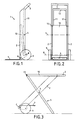
- eine Seitenansicht eines Mehrzweck-Handkarrens in der Sackkarren-Stellung,
- Fig. 2
- eine Vorderansicht des Handkarrens gem. Fig. 1,
- Fig. 3
- eine Seitenansicht des Handkarrens nach Fig. 1 in der Tischstellung und
- Fig. 4
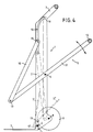
- einen Längsschnitt des Handkarrens nach Fig. 1 in größerem Maßstab.
- Fig. 1
- a side view of a multi-purpose handcart in the handcart position,
- Fig. 2
- a front view of the handcart acc. Fig. 1
- Fig. 3
- a side view of the handcart according to Fig. 1 in the table position and
- Fig. 4
- a longitudinal section of the handcart according to FIG. 1 on a larger scale.
Für seine Funktion als Sackkarren nach den Figuren 1 und 2 umfaßt der Mehrzweck-Handkarren einen Rahmen (1) aus zwei parallelen leistenförmigen Holmen (2), die oben durch einen schrägstehenden Griffbügel (3), im mittleren Bereich durch die Achse (4) eines Stützgestells (5) und im unteren Bereich durch die Achse (6) einer Tragschaufel (7) sowie durch die Achse (8) zweier außen angebrachter Räder (9) miteinander verbunden sind. Eine zwischen die Holme (2) eingesenkte Tischplatte (10) kann als Stützfläche für eine auf der Tragschaufel ruhende Last dienen. Zum Aufbewahren kann die Tragschaufel (7) in die Stellung (7′) gemäß Fig. 4 eingeklappt werden, in welcher sie an der Tischplatte (10) anstößt.For its function as a hand truck according to Figures 1 and 2, the multi-purpose handcart comprises a frame (1) made of two parallel strip-shaped bars (2), the top by an inclined handle (3), in the central area by the axis (4) one Support frame (5) and in the lower region by the axis (6) of a support blade (7) and by the axis (8) of two externally attached wheels (9). A table top (10) countersunk between the bars (2) can serve as a support surface for a load resting on the carrying blade. For storage, the carrying scoop (7) can be folded into the position (7 ') according to FIG. 4, in which it abuts the table top (10).
Das um die Achse (4) schwenkbare Stützgestell (5) bildet ebenfalls einen Rahmen aus zwei Schenkeln (11), die an dem nach den Figuren 1 und 2 oberen Ende durch einen Querschenkel (12) zusammengehalten und an den beiden anderen Enden mit der Tischplatte (10) schwenkbar verbunden sind, wobei die Schwenkachse (13) die eine Querkante der Tischplatte bildet. In Verlängerung der gegenüberliegenden Querkante weist die Tischplatte (10) zwei Zapfen (14) auf, welche in Nuten (15) an den Innenflächen der Holme (2) eingreifen (Fig. 4). In ihrem oberen Endbereich verläuft die Nut (15) in einer Kurve nach rechts, wobei sie asymptotisch in die Richtung einschwenkt, die durch den Griffbügel (3) und die Verlängerung des Tisches (10) in seiner Benutzungsstellung nach Fig. 3 vorgegeben ist. Schließlich enden die Nuten in Abwinkelungen nach unten bzw. in Fangtaschen (16).The support frame (5) which can be pivoted about the axis (4) likewise forms a frame made up of two legs (11) which are held together at the upper end according to FIGS. 1 and 2 by a cross leg (12) and at the other two ends with the table top (10) are pivotally connected, the pivot axis (13) forming a transverse edge of the table top. In extension of the opposite transverse edge, the table top (10) has two pins (14) which engage in grooves (15) on the inner surfaces of the spars (2) (Fig. 4). In its upper end region, the groove (15) runs to the right in a curve, pivoting asymptotically in the direction which is predetermined by the handle bar (3) and the extension of the table (10) in its use position according to FIG. 3. Finally, the grooves end in downward bends or in catch pockets (16).
Um den Sackkarren in einen fahrbaren Beistelltisch zu verwandeln hält man mit einer Hand den Griffbügel (3) und schwenkt mit der anderen das Stützgestell (5), das man an dem Querschenkel (12) hält, aus dem Rahmen (1) heraus, bis es quer zu diesem steht. Dabei werden die Zapfen (14) der Tischplatte unter gleichzeitiger Schwenkung in der Nut (15) nach oben verschoben, bis die Zapfen (14) in die Fangtaschen (16) einfallen. Dann wird die Vorrichtung gemäß Fig. 3 abgestellt. Sie ruht jetzt auf den Rädern (9) und dem Stützgestell (5) und die Tischplatte (10) nimmt eine horizontale Stellung ein und wird durch den ebenfalls horizontalen Griffbügel (3) verlängert. Zum Zusammenklappen wird die Tischplatte (10) an der zapfenseitigen Kante leicht angehoben, so daß die Zapfen (14) die Fangtaschen (16) verlassen, wonach das Stützgestell (5) wieder in seine Ruhestellung nach Fig. 1 zurückgeführt werden kann und die Tischplatte entsprechend nach unten wandert.To turn the hand truck into a mobile side table, hold the handle (3) with one hand and swivel the support frame (5), which is held on the cross leg (12), out of the frame (1) with the other until it is perpendicular to this. The pins (14) of the table top are shifted upwards while simultaneously pivoting in the groove (15) until the pins (14) fall into the catch pockets (16). Then the device according to FIG. 3 is switched off. It now rests on the wheels (9) and the support frame (5) and the table top (10) assumes a horizontal position and is extended by the handle bar (3), which is also horizontal. To fold the table top (10) is slightly raised at the pin-side edge, so that the pin (14) leave the pockets (16), after which the support frame (5) can be returned to its rest position according to FIG. 1 and the table top accordingly wanders down.
Wie insbesondere Fig. 4 zeigt hat die Tragschaufel (7) zwei Lageraugen (17), die ihr einen Abstand von ihrer Achse (6) geben. In der ausgezogen gezeichneten Sackkarrenstellung stoßen diese Lageraugen (17) an Anschlägen (18) an, die fest an den Holmen (2) sitzen. In der strichpunktiert gezeichneten Stellung (7′′) erstreckt sich die Tragschaufel zwischen den Holmen (2) hindurch, wobei sie auf entsprechenden Anschlägen (19) aufliegt. Sie befindet sich jetzt mit der Unterseite nach oben in horizontaler Stellung (Fig. 3) und kann so als weitere Ablagefläche dienen.As shown in FIG. 4 in particular, the carrying blade (7) has two bearing eyes (17) which give it a distance from its axis (6). In the drawn sack truck position, these bearing eyes (17) abut stops (18) which are firmly seated on the bars (2). In the dash-dotted position (7 '') extends the carrying blade extends between the spars (2), resting on corresponding stops (19). It is now in the horizontal position with the underside facing upwards (FIG. 3) and can thus serve as a further storage surface.
Claims (8)
- A multi-purpose hand cart, which can be transformed into a table, having an outer and an inner frame (1, 5), which in their central region can be swivellably connected to one another around a horizontal axis (4), having two wheels (9), which are rotatably fixed around a horizontal axle (8) at one end of a frame (1), having a table top (10), which with one end region is connected in a swivelling manner to the end region of one frame (5) and with its other end region is displaceably connected to the other frame (1), and also having a carrying plate (7) pivoted in the region of the axle (8) of the wheels (9),
characterised in that the outer frame (1) is constructed as a solid, closed main frame, which extends over the entire length of the hand cart, in the interior of which the inner frame (5) constructed as a support frame and the desk top (10) are disposed and at the upper end region of which is constructed a handle (3), which is inclined to the frame (1) and aligns with the desk top (10) in the table position, and the widened lower region of which comprises on the rear, in relation to the direction of travel, the axle (8), while a horizontal axis (6) for the carrying plate (7) is disposed on the front side. - A multi-purpose hand cart according to Claim 1,
characterised in that the carrying plate (7) is mounted by means of bearing lugs (17) on the axis (6) and can be swung out of a horizontal position of use into a table position of the hand cart, also a horizontal position of rest. - A multi-purpose hand cart according to Claim 2,
characterised in that stops (18, 19) are constructed on the outer frame (1) to limit the position of use and the position of rest of the carrying plate (7). - A multi-purpose hand cart according to one of Claims 1 to 3,
characterised in that the front, lower end region of the outer frame (1) is extended to support the outer frame (1) in a substantially vertical position. - A multi-purpose hand cart according to one of Claims 1 to 4,
characterised in that auxiliary wheels are mounted on the inner frame (5). - A multi-purpose hand cart according to one of Claims 1 to 5,
characterised in that the table top (10) having round journals (14) protruding in the transverse direction is guided in grooves (15) on the facing inner sides of bars (2) of the outer frame (1). - A multi-purpose hand cart according to Claim 6,
characterised in that the grooves (15) extend at the upper region of the bars (2) and in a region of the handle (3). - A multi-purpose hand cart according to Claim 7,
characterised in that at their end in the region of the handle (3) the grooves (15) are provided with a downwardly directed catch (16).
Applications Claiming Priority (2)
| Application Number | Priority Date | Filing Date | Title |
|---|---|---|---|
| DE19873725021 DE3725021A1 (en) | 1987-07-29 | 1987-07-29 | MULTIPURPOSE CART |
| DE3725021 | 1987-07-29 |
Publications (3)
| Publication Number | Publication Date |
|---|---|
| EP0301418A2 EP0301418A2 (en) | 1989-02-01 |
| EP0301418A3 EP0301418A3 (en) | 1990-04-11 |
| EP0301418B1 true EP0301418B1 (en) | 1994-03-02 |
Family
ID=6332551
Family Applications (1)
| Application Number | Title | Priority Date | Filing Date |
|---|---|---|---|
| EP88111796A Expired - Lifetime EP0301418B1 (en) | 1987-07-29 | 1988-07-22 | Multipurpose handcart |
Country Status (5)
| Country | Link |
|---|---|
| US (1) | US4934718A (en) |
| EP (1) | EP0301418B1 (en) |
| CA (1) | CA1308136C (en) |
| DE (2) | DE3725021A1 (en) |
| ES (1) | ES2051803T3 (en) |
Families Citing this family (41)
| Publication number | Priority date | Publication date | Assignee | Title |
|---|---|---|---|---|
| JP2725258B2 (en) * | 1987-09-25 | 1998-03-11 | 三菱電機株式会社 | Integrated circuit device |
| GB2247612A (en) * | 1990-09-04 | 1992-03-11 | Ronald Frederick Wright | Table convertible to a trolley |
| US5257892A (en) * | 1991-11-04 | 1993-11-02 | David Branch | Multiple purpose transporting device |
| US5704919A (en) * | 1992-12-04 | 1998-01-06 | Travenol Laboratories (Israel) Ltd. | Intravenous cannula assembly |
| IL103973A (en) * | 1992-12-04 | 1998-09-24 | Travenol Lab Israel Ltd | Intravenous cannula assembly |
| GB2293757A (en) * | 1994-10-04 | 1996-04-10 | Martin Alexander Humphrey | Collapsible table convertible to a wheelbarrow |
| US5669659A (en) * | 1996-08-20 | 1997-09-23 | Dittmer; Thomas E. | Combination chair and hand truck |
| US6003881A (en) * | 1997-09-17 | 1999-12-21 | Reebok Interantional Ltd. | Variable training resistance device |
| US6158749A (en) * | 1997-09-25 | 2000-12-12 | Cosco Management, Inc. | Step stool and dolly apparatus |
| US6578856B2 (en) * | 2000-01-10 | 2003-06-17 | W. Scott Kahle | Collapsible portable saw stand |
| US7648155B1 (en) * | 2000-03-02 | 2010-01-19 | Wise Robert W | Universal mobile saw stand |
| FR2809291B1 (en) * | 2000-05-23 | 2003-02-07 | Gilles Dumoulin | EXTENDABLE AND FOLDABLE TROLLEY, PARTICULARLY FOR TOOL CASE |
| US6474663B1 (en) * | 2000-07-07 | 2002-11-05 | Jimmy J. Becker | Combined pair of ladders and transportation dolly device |
| US7188843B2 (en) * | 2000-08-29 | 2007-03-13 | Annop Magness | Multiuse lifting and rolling platform |
| US7032910B2 (en) * | 2002-05-13 | 2006-04-25 | Baxter International Inc. | Adaptable blood processing platforms |
| US6880851B1 (en) | 2002-09-27 | 2005-04-19 | Deborah Dale Summers | Hand cart |
| US6886836B1 (en) * | 2002-12-05 | 2005-05-03 | Robert W. Wise | Counterbalanced universal mobile saw stand |
| US6945545B2 (en) * | 2003-01-22 | 2005-09-20 | Giuliano Celli | Multi function hand truck |
| WO2005016601A2 (en) | 2003-08-05 | 2005-02-24 | Black & Decker Inc. | Folding bench with hand truck capabilities |
| WO2006012561A2 (en) * | 2004-07-22 | 2006-02-02 | Kenneth Gayle Sebastian | Self attaching ladder dolly and method |
| CN1712291A (en) * | 2004-10-13 | 2005-12-28 | 卢涛 | Multifunctional stand |
| US7588255B2 (en) * | 2004-11-10 | 2009-09-15 | Zag Industries, Ltd. | Collapsible clamping work table |
| US7726669B2 (en) | 2005-01-14 | 2010-06-01 | Patricia Lynn Alexander | Apparatus for a collapsible table and dolly |
| US7306245B1 (en) | 2005-04-04 | 2007-12-11 | Archie Lowe | Multipurpose work site utility carrier |
| US20060279053A1 (en) * | 2005-06-11 | 2006-12-14 | Reynolds John C | Adjustable load support for hand trucks |
| US8191906B2 (en) * | 2006-02-13 | 2012-06-05 | Steven Michael Jensen | Modular utility stand storage apparatus and method |
| US7543614B2 (en) * | 2007-03-13 | 2009-06-09 | Wise Robert W | Collapsible infeed/outfeed table |
| US8464994B2 (en) * | 2008-10-22 | 2013-06-18 | Rexon Industrial Corp., Ltd. | Folding tool stand |
| US7971898B2 (en) * | 2009-04-30 | 2011-07-05 | Wise Robert W | Multiple link, self-jacking work cart wa002 |
| USD608969S1 (en) | 2009-04-30 | 2010-01-26 | Wise Robert W | Self-jacking four wheel cart |
| US20110057402A1 (en) * | 2009-09-09 | 2011-03-10 | Keith Jewell | Multi-functional and convertible hand truck |
| CN102092043B (en) * | 2010-12-07 | 2012-07-25 | 常熟通润汽车零部件股份有限公司 | Repair creeper |
| US8910970B2 (en) * | 2011-06-10 | 2014-12-16 | Rexon Industrial Corp., Ltd. | Rapidly collapsible stand |
| USD660543S1 (en) | 2011-06-28 | 2012-05-22 | Ken J. Pedersen | Garden cart top |
| US8770597B1 (en) | 2012-06-27 | 2014-07-08 | Howard Phillips | Collapsible shelf and dolly system |
| TWM505312U (en) * | 2015-02-26 | 2015-07-21 | guo-ji Zhang | Chemical leakage processing vehicle |
| TWI616369B (en) * | 2016-10-07 | 2018-03-01 | 李訓忠 | Deformable carrier with transport mode and fixed mode |
| US10160467B2 (en) * | 2017-01-11 | 2018-12-25 | Greg Josephsen | Convertible cart device |
| US10813446B2 (en) | 2019-03-21 | 2020-10-27 | Robert Wise | Collapsible infeed/outfeed table with shelf |
| US11027413B2 (en) | 2019-03-21 | 2021-06-08 | Robert Wise | Collapsible infeed/outfeed apparatus with shelf |
| US11890744B2 (en) * | 2020-07-31 | 2024-02-06 | Techtronic Cordless Gp | Workbench-hand truck assembly |
Family Cites Families (13)
| Publication number | Priority date | Publication date | Assignee | Title |
|---|---|---|---|---|
| US1081221A (en) * | 1912-12-26 | 1913-12-09 | Maude Durkin | Carriage for hand-luggage. |
| DE474474C (en) * | 1927-09-03 | 1929-04-03 | Gustav Roediger | Hand truck with table |
| GB866536A (en) * | 1957-07-09 | 1961-04-26 | Slovenijales Podjetje Za Izvoz | Folding trolley |
| US3082016A (en) * | 1960-09-28 | 1963-03-19 | William D Pratt | Auto cart |
| DE1863469U (en) * | 1962-08-29 | 1962-12-06 | Larisch Geb | FOLDABLE BAG TROLLEY. |
| US3147748A (en) * | 1963-04-22 | 1964-09-08 | Elmer N Frank | Combined barbecue grill and hand truck |
| US3430972A (en) * | 1966-08-11 | 1969-03-04 | Armin Fiedler | Combined stepladder-cart |
| AU1890967A (en) * | 1968-03-14 | 1969-09-18 | Improved hand trolley | |
| DE1779787A1 (en) * | 1968-09-26 | 1971-09-16 | Richard Simonian | Collapsible serving trolley |
| GB2051690B (en) * | 1979-05-15 | 1983-04-27 | Int Computers Ltd | Dual-purpose wheeled trolley/work surface |
| US4284286A (en) * | 1979-08-02 | 1981-08-18 | Lewallen Charles D | Combination handtruck and portable work table |
| IT8321973U1 (en) * | 1983-05-26 | 1984-11-26 | Black & Decker Inc | UNIVERSAL MULTIPURPOSE TROLLEY WITH MOVABLE WHEELS AND VERTICAL ALIGNMENT |
| US4565382A (en) * | 1984-03-23 | 1986-01-21 | Sherman William S | Combined portable table and hand truck |
-
1987
- 1987-07-29 DE DE19873725021 patent/DE3725021A1/en not_active Withdrawn
-
1988
- 1988-07-20 CA CA000572561A patent/CA1308136C/en not_active Expired - Lifetime
- 1988-07-22 ES ES88111796T patent/ES2051803T3/en not_active Expired - Lifetime
- 1988-07-22 EP EP88111796A patent/EP0301418B1/en not_active Expired - Lifetime
- 1988-07-22 DE DE88111796T patent/DE3888039D1/en not_active Expired - Fee Related
- 1988-07-28 US US07/225,419 patent/US4934718A/en not_active Expired - Fee Related
Also Published As
| Publication number | Publication date |
|---|---|
| EP0301418A2 (en) | 1989-02-01 |
| DE3725021A1 (en) | 1989-02-09 |
| EP0301418A3 (en) | 1990-04-11 |
| US4934718A (en) | 1990-06-19 |
| DE3888039D1 (en) | 1994-04-07 |
| ES2051803T3 (en) | 1994-07-01 |
| CA1308136C (en) | 1992-09-29 |
Similar Documents
| Publication | Publication Date | Title |
|---|---|---|
| EP0301418B1 (en) | Multipurpose handcart | |
| DE3876839T2 (en) | CHAIR AND CARRIAGE COMBINATION. | |
| DE3423528C2 (en) | Dolly | |
| DE3702846C2 (en) | ||
| DE3705187C2 (en) | ||
| DE3419685A1 (en) | MULTIPURPOSE CART | |
| DE8812023U1 (en) | Shopping cart with a transport basket arranged on its upper part | |
| DE2939003A1 (en) | USED CARS | |
| DE2800575C2 (en) | Stackable transport trolley | |
| DE60017122T2 (en) | COLLAPSIBLE CARRIER WITH SHELVES | |
| EP0569988B1 (en) | Transport cart for pallet-type objects | |
| DE2947586C2 (en) | Foldable bed that can be used to transport objects | |
| EP0207419B1 (en) | Tool box | |
| DE4019081A1 (en) | Folding trolley for transporting luggage - has telescopic side members hinged together at trolley handle | |
| DE4018948C2 (en) | Fishing trolleys for fishing | |
| WO1998056640A1 (en) | Skibob | |
| DE3444256C2 (en) | Stackable shopping cart | |
| DE8904428U1 (en) | Stackable shopping cart | |
| WO2001019213A1 (en) | Suitcase | |
| EP0767097B1 (en) | Trolley, especially for panels | |
| DE69401262T2 (en) | DIFFERENTLY USED BABY CARRYING DEVICE | |
| DE7917706U1 (en) | TRANSPORT CART | |
| DE8812022U1 (en) | Trolley for transporting luggage | |
| EP0634311A2 (en) | Stair climbing handtruck | |
| WO2025024878A1 (en) | Wheelbarrow for transporting a load |
Legal Events
| Date | Code | Title | Description |
|---|---|---|---|
| PUAI | Public reference made under article 153(3) epc to a published international application that has entered the european phase |
Free format text: ORIGINAL CODE: 0009012 |
|
| AK | Designated contracting states |
Kind code of ref document: A2 Designated state(s): DE ES FR GB IT SE |
|
| PUAL | Search report despatched |
Free format text: ORIGINAL CODE: 0009013 |
|
| AK | Designated contracting states |
Kind code of ref document: A3 Designated state(s): DE ES FR GB IT SE |
|
| 17P | Request for examination filed |
Effective date: 19901207 |
|
| 17Q | First examination report despatched |
Effective date: 19920626 |
|
| RAP1 | Party data changed (applicant data changed or rights of an application transferred) |
Owner name: HEINZ KETTLER METALLWARENFABRIK GMBH & CO |
|
| GRAA | (expected) grant |
Free format text: ORIGINAL CODE: 0009210 |
|
| AK | Designated contracting states |
Kind code of ref document: B1 Designated state(s): DE ES FR GB IT SE |
|
| REF | Corresponds to: |
Ref document number: 3888039 Country of ref document: DE Date of ref document: 19940407 |
|
| GBT | Gb: translation of ep patent filed (gb section 77(6)(a)/1977) |
Effective date: 19940314 |
|
| ET | Fr: translation filed | ||
| ITF | It: translation for a ep patent filed | ||
| REG | Reference to a national code |
Ref country code: ES Ref legal event code: FG2A Ref document number: 2051803 Country of ref document: ES Kind code of ref document: T3 |
|
| PLBE | No opposition filed within time limit |
Free format text: ORIGINAL CODE: 0009261 |
|
| STAA | Information on the status of an ep patent application or granted ep patent |
Free format text: STATUS: NO OPPOSITION FILED WITHIN TIME LIMIT |
|
| EAL | Se: european patent in force in sweden |
Ref document number: 88111796.4 |
|
| 26N | No opposition filed | ||
| PGFP | Annual fee paid to national office [announced via postgrant information from national office to epo] |
Ref country code: GB Payment date: 19970714 Year of fee payment: 10 |
|
| PGFP | Annual fee paid to national office [announced via postgrant information from national office to epo] |
Ref country code: SE Payment date: 19970729 Year of fee payment: 10 |
|
| PGFP | Annual fee paid to national office [announced via postgrant information from national office to epo] |
Ref country code: FR Payment date: 19970730 Year of fee payment: 10 Ref country code: DE Payment date: 19970730 Year of fee payment: 10 |
|
| PGFP | Annual fee paid to national office [announced via postgrant information from national office to epo] |
Ref country code: ES Payment date: 19970731 Year of fee payment: 10 |
|
| PG25 | Lapsed in a contracting state [announced via postgrant information from national office to epo] |
Ref country code: GB Free format text: LAPSE BECAUSE OF NON-PAYMENT OF DUE FEES Effective date: 19980722 |
|
| PG25 | Lapsed in a contracting state [announced via postgrant information from national office to epo] |
Ref country code: SE Free format text: LAPSE BECAUSE OF NON-PAYMENT OF DUE FEES Effective date: 19980723 Ref country code: ES Free format text: LAPSE BECAUSE OF THE APPLICANT RENOUNCES Effective date: 19980723 |
|
| GBPC | Gb: european patent ceased through non-payment of renewal fee |
Effective date: 19980722 |
|
| EUG | Se: european patent has lapsed |
Ref document number: 88111796.4 |
|
| PG25 | Lapsed in a contracting state [announced via postgrant information from national office to epo] |
Ref country code: FR Free format text: LAPSE BECAUSE OF NON-PAYMENT OF DUE FEES Effective date: 19990331 |
|
| PG25 | Lapsed in a contracting state [announced via postgrant information from national office to epo] |
Ref country code: DE Free format text: LAPSE BECAUSE OF NON-PAYMENT OF DUE FEES Effective date: 19990501 |
|
| REG | Reference to a national code |
Ref country code: FR Ref legal event code: ST |
|
| REG | Reference to a national code |
Ref country code: ES Ref legal event code: FD2A Effective date: 20001102 |
|
| PG25 | Lapsed in a contracting state [announced via postgrant information from national office to epo] |
Ref country code: IT Free format text: LAPSE BECAUSE OF NON-PAYMENT OF DUE FEES;WARNING: LAPSES OF ITALIAN PATENTS WITH EFFECTIVE DATE BEFORE 2007 MAY HAVE OCCURRED AT ANY TIME BEFORE 2007. THE CORRECT EFFECTIVE DATE MAY BE DIFFERENT FROM THE ONE RECORDED. Effective date: 20050722 |