EP0301227B1 - Device for the random selection of segments of a movable wall on a roller conveyor - Google Patents
Device for the random selection of segments of a movable wall on a roller conveyor Download PDFInfo
- Publication number
- EP0301227B1 EP0301227B1 EP88109763A EP88109763A EP0301227B1 EP 0301227 B1 EP0301227 B1 EP 0301227B1 EP 88109763 A EP88109763 A EP 88109763A EP 88109763 A EP88109763 A EP 88109763A EP 0301227 B1 EP0301227 B1 EP 0301227B1
- Authority
- EP
- European Patent Office
- Prior art keywords
- movable wall
- shaft
- segments
- roller conveyor
- sleeve
- Prior art date
- Legal status (The legal status is an assumption and is not a legal conclusion. Google has not performed a legal analysis and makes no representation as to the accuracy of the status listed.)
- Expired - Lifetime
Links
Images
Classifications
-
- B—PERFORMING OPERATIONS; TRANSPORTING
- B21—MECHANICAL METAL-WORKING WITHOUT ESSENTIALLY REMOVING MATERIAL; PUNCHING METAL
- B21B—ROLLING OF METAL
- B21B43/00—Cooling beds, whether stationary or moving; Means specially associated with cooling beds, e.g. for braking work or for transferring it to or from the bed
- B21B43/003—Transfer to bed
-
- B—PERFORMING OPERATIONS; TRANSPORTING
- B65—CONVEYING; PACKING; STORING; HANDLING THIN OR FILAMENTARY MATERIAL
- B65G—TRANSPORT OR STORAGE DEVICES, e.g. CONVEYORS FOR LOADING OR TIPPING, SHOP CONVEYOR SYSTEMS OR PNEUMATIC TUBE CONVEYORS
- B65G47/00—Article or material-handling devices associated with conveyors; Methods employing such devices
- B65G47/74—Feeding, transfer, or discharging devices of particular kinds or types
- B65G47/82—Rotary or reciprocating members for direct action on articles or materials, e.g. pushers, rakes, shovels
Definitions
- This invention concerns according to the preamble of claim 1 a device for the random selection of segments of a movable wall on a roller conveyor which discharges rolled bars.
- the invention concerns a device suitable to make possible a random or desired selection of part or the whole of the movable wall of a roller conveyor which discharges rolled bars and cooperates with a cooling plate or other means.
- the movable walls of roller conveyors discharging rolled bars consist of one or more segments, but all the segments are actuated together in the same manner.
- roller conveyors are tilted and the retraction of the movable wall enables the rolled stock to slide sideways and thus to be discharged onto a cooling plate.
- roller conveyors the problem often arises of having to discharge a segment of the rolled stock (the head of a bar, for instance) or one rolled element in a desired manner without interfering thereby with the other rolled elements sliding on the roller conveyor.
- DE-OS-1527710 discloses a plurality of aligned, successive movable wall elements connected to one single shaft and actuated all together or in pre-selected assemblies. This proposal is an improvement as regards the state of the art but entails the shortcoming that the assemblies actuated at the same time are pre-selected and are not chosen on each occasion according to the actual braking requirements.
- the present applicant has designed, tested and embodied the present invention, according to which the movable wall which determines by its retraction the lateral discharge of the rolled stock is divided into a number of successive independent segments.
- each independent segment can be moved in coordination with the other segment or be moved or clamped in an independent manner.
- the device is extremely simple and reliable.
- the invention therefore consists of a device for the random selection of segments of a movable wall on a roller conveyor for the discharge of rolled stock having the features of the main claim, the connected dependent claims disclosing variants of the basic idea.
- a roller conveyor 10 with tilted rolls positioned crosswise to the roller conveyor cooperates with movable wall segments 11 in the lateral discharge of rolled bars 23 sliding on the roller conveyor 10.
- Lateral discharge delivers the bars 23 onto a cooling plate 24 or other means.
- a hinged vane 25 is provided to separate the head of one bar from another or one element from the successive element and retains momentarily a successive element 123 until the preceding element 23 has been discharged in a straight direction or laterally, depending on what the specific preceding element 23 is.
- This embodiment is unsatisfactory.
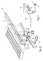
- a movable wall 11 is divided into a plurality of segments 111, 211, etc. positioned side by side in succession, each segment being independent of the preceding and successive segments.
- An operating shaft 12 of a type known in itself is comprised in cooperation with the movable wall 11 and is actuated by a hydraulic cylinder 14 through a lever 13.
- a frontal ring 18 which cooperates with a sleeve 17 is comprised for each movable wall segment 111, 211, and is solidly fixed to the shaft 12, whereas the sleeve 17 can oscillate on the shaft 12.
- a frontal connection is provided between the frontal ring 18 and sleeve 17 by means of a slot 20 and tooth 19.
- the positioning of the slot 20 and tooth 19 respectively on the ring 18 and/or on the sleeve 17 depends on the choice made during design work.
- the slot 20 is considerably longer than the thickness of the tooth 19, so that the tooth 19 can move to a certain extent in a circumferential direction within the slot 20.
- the sleeve 17 comprises one or more rear levers 22 cooperating with respective connecting rods 16 which act on one single movable wall segment 111, 211.
- the sleeve 17 comprises also a frontal lever 21 cooperating with a pneumatic cylinder 15.
- the actuation of the hydraulic cylinder 14, therefore, lowers or raises the movable wall segment 11 by coordinated movement with angular rotation of the shaft 12.
- the tooth 19 is made to slide circumferentially within the slot 20.
- the specific movable segment chosen is thrust upwards and kept up also during rotation of the shaft 12, which moves the other specific movable segments.
- the slot 20 is not able to engage the tooth 19.
- the position of the specific movable segment 11 can be inverted very simply by inverting the coordinated relationship between the tooth 19 and slot 20.
- the movable wall segments 11 may be of various types and have a varied type of coordinated relationship with the roller discharge conveyor 10 and plate 24.
Abstract
Description
- This invention concerns according to the preamble of claim 1 a device for the random selection of segments of a movable wall on a roller conveyor which discharges rolled bars.
- To be more exact, the invention concerns a device suitable to make possible a random or desired selection of part or the whole of the movable wall of a roller conveyor which discharges rolled bars and cooperates with a cooling plate or other means.
- At the present time the movable walls of roller conveyors discharging rolled bars consist of one or more segments, but all the segments are actuated together in the same manner.
- The roller conveyors are tilted and the retraction of the movable wall enables the rolled stock to slide sideways and thus to be discharged onto a cooling plate.
- On such roller conveyors the problem often arises of having to discharge a segment of the rolled stock (the head of a bar, for instance) or one rolled element in a desired manner without interfering thereby with the other rolled elements sliding on the roller conveyor.
- To do so with the known art, it is necessary to create perfect coordination between the arrival of the rolled stock to be discharged and the moment when the movable wall is made to descend and ascend, so that the previous rolled element and the subsequent one do not have to undergo the same action as the element which has to be discharged in a manner independent of the other elements.
- With the known art it is possible to retain an arriving element by means of an appropriate hinged vane until the previous element has been discharged.
- DE-OS-1527710 discloses a plurality of aligned, successive movable wall elements connected to one single shaft and actuated all together or in pre-selected assemblies. This proposal is an improvement as regards the state of the art but entails the shortcoming that the assemblies actuated at the same time are pre-selected and are not chosen on each occasion according to the actual braking requirements.
- So as to be able to discharge the rolled stock from a roller conveyor in a random or desired manner without any need even of auxiliary hinged vanes, the present applicant has designed, tested and embodied the present invention, according to which the movable wall which determines by its retraction the lateral discharge of the rolled stock is divided into a number of successive independent segments.
- According to the invention each independent segment can be moved in coordination with the other segment or be moved or clamped in an independent manner. The device is extremely simple and reliable.
- The invention therefore consists of a device for the random selection of segments of a movable wall on a roller conveyor for the discharge of rolled stock having the features of the main claim, the connected dependent claims disclosing variants of the basic idea.
- The attached figures give a non-restrictive simplified example of the embodiment of the invention and show in Fig.1 the known hinged separation vane.
- A
roller conveyor 10 with tilted rolls positioned crosswise to the roller conveyor cooperates withmovable wall segments 11 in the lateral discharge of rolledbars 23 sliding on theroller conveyor 10. - Lateral discharge delivers the
bars 23 onto acooling plate 24 or other means. - The coordinated working of the
movable wall segments 11 and theroller conveyor 10 in the discharge of rolled bars is already known and is not re-disclosed here. - In the known art a
hinged vane 25 is provided to separate the head of one bar from another or one element from the successive element and retains momentarily asuccessive element 123 until the precedingelement 23 has been discharged in a straight direction or laterally, depending on what the specific precedingelement 23 is. This embodiment is unsatisfactory. - According to the invention a
movable wall 11 is divided into a plurality ofsegments - Such independence or coordinated connection is a condition desired by the machine operator and is made possible by the invention.
- An
operating shaft 12 of a type known in itself is comprised in cooperation with themovable wall 11 and is actuated by ahydraulic cylinder 14 through alever 13. - A
frontal ring 18 which cooperates with asleeve 17 is comprised for eachmovable wall segment shaft 12, whereas thesleeve 17 can oscillate on theshaft 12. - A frontal connection is provided between the
frontal ring 18 andsleeve 17 by means of aslot 20 andtooth 19. - The positioning of the
slot 20 andtooth 19 respectively on thering 18 and/or on thesleeve 17 depends on the choice made during design work. - The
slot 20 is considerably longer than the thickness of thetooth 19, so that thetooth 19 can move to a certain extent in a circumferential direction within theslot 20. - The
sleeve 17 comprises one or morerear levers 22 cooperating with respective connectingrods 16 which act on one singlemovable wall segment - The
sleeve 17 comprises also afrontal lever 21 cooperating with apneumatic cylinder 15. - The method of working is so far implicit. Vertical actuation of the
movable wall 11 is performed by thehydraulic cylinder 14, which by means of its force is able to overcome the thrust of the plurality ofpneumatic cylinders 15 that normally keep thetooth 19 in working connection with theslot 20. - The actuation of the
hydraulic cylinder 14, therefore, lowers or raises themovable wall segment 11 by coordinated movement with angular rotation of theshaft 12. - When it is desired to separate the movement of the specific segment of the
movable wall pneumatic cylinder 15, which in this case draws thefrontal lever 21 towards itself and thrusts therear lever 22 upwards. - In the meantime the
tooth 19 is made to slide circumferentially within theslot 20. In this way the specific movable segment chosen is thrust upwards and kept up also during rotation of theshaft 12, which moves the other specific movable segments. In fact, theslot 20 is not able to engage thetooth 19. - If so desired, the position of the specific
movable segment 11 can be inverted very simply by inverting the coordinated relationship between thetooth 19 andslot 20. - The
movable wall segments 11 may be of various types and have a varied type of coordinated relationship with theroller discharge conveyor 10 andplate 24.
Claims (3)
- Device for the random selection of segments of a movable wall (11) on roller conveyors (10) which discharge rolled bars (23) laterally, whereby the movable wall (11) can descend and ascend in relationship with the roller conveyor (10) and a cooling plate (24), the roller conveyor (10) lying on a plane tilted towards the movable wall (11), the movable wall (11) being divided into a plurality of specific aligned segments (111-211.....) which succeed one another, the specific segments being actuated by one single actuation shaft (12), the device being characterized in that the shaft (12) can be actuated at an angle on its axis and that the device comprises a frontal ring (18) cooperating with a sleeve (17) able to oscillate independently on the shaft (12), the sleeve (17) being connected to the specific segment (111-211.....), whereas the ring (18) is integrally connected to the shaft (12), a temporary insertion means (15) being included between the ring (18) and the sleeve (17), a tooth (19) and a slot (20) being also comprised between the sleeve (17) and ring (18), the slot (20) being longer than the width of the tooth (19).
- Device as claimed in Claim 1, in which the shaft (12) is actuated at an angle by a hydraulic cylinder (14).
- Device as claimed in Claim 1 or 2, in which the temporary insertion means (15) that actuates each of the sleeves (17) circumferentially is a pneumatic cylinder (15), the thrust of the number "N" of pneumatic cylinders (15) being less strong than the thrust of the hydraulic cylinder (14) that actuates the shaft (12) at an angle to the axis of the shaft (12).
Priority Applications (1)
| Application Number | Priority Date | Filing Date | Title |
|---|---|---|---|
| AT88109763T ATE70205T1 (en) | 1987-07-31 | 1988-06-18 | DEVICE FOR ANY CHOICE OF SEGMENTS OF A MOVABLE WALL OF A ROLLER CONVEYOR. |
Applications Claiming Priority (2)
| Application Number | Priority Date | Filing Date | Title |
|---|---|---|---|
| IT8342187 | 1987-07-31 | ||
| IT83421/87A IT1221714B (en) | 1987-07-31 | 1987-07-31 | ROLLER CURSOR ZONE CASE SELECTOR |
Publications (2)
| Publication Number | Publication Date |
|---|---|
| EP0301227A1 EP0301227A1 (en) | 1989-02-01 |
| EP0301227B1 true EP0301227B1 (en) | 1991-12-11 |
Family
ID=11321645
Family Applications (1)
| Application Number | Title | Priority Date | Filing Date |
|---|---|---|---|
| EP88109763A Expired - Lifetime EP0301227B1 (en) | 1987-07-31 | 1988-06-18 | Device for the random selection of segments of a movable wall on a roller conveyor |
Country Status (6)
| Country | Link |
|---|---|
| US (1) | US4895246A (en) |
| EP (1) | EP0301227B1 (en) |
| AT (1) | ATE70205T1 (en) |
| DE (1) | DE3866812D1 (en) |
| ES (1) | ES2028949T3 (en) |
| IT (1) | IT1221714B (en) |
Families Citing this family (3)
| Publication number | Priority date | Publication date | Assignee | Title |
|---|---|---|---|---|
| EP1189707A4 (en) * | 1999-04-30 | 2008-03-05 | Siemens Ag | Item singulation system |
| WO2009026533A1 (en) * | 2007-08-22 | 2009-02-26 | Laitram, L.L.C. | Belt conveyors with retractable wall segments |
| EP2252838A1 (en) * | 2008-02-20 | 2010-11-24 | UTC Fire & Safety Corp. | Assisted commissioning method for combustion control systems |
Family Cites Families (7)
| Publication number | Priority date | Publication date | Assignee | Title |
|---|---|---|---|---|
| US1398818A (en) * | 1920-12-16 | 1921-11-29 | Nat Tube Co | Automatic dump-trough-operating apparatus |
| US1929487A (en) * | 1931-06-06 | 1933-10-10 | Feller Karl | Mechanism for handling rolled stock |
| DE1527710C3 (en) * | 1966-03-09 | 1975-05-22 | Schloemann-Siemag Ag, 4000 Duesseldorf | Accumulation roller table for guiding, separating and braking partial and remaining lengths, preferably behind fine steel lines for transferring to a cooling bed |
| US3880751A (en) * | 1973-12-27 | 1975-04-29 | Speaker Motion Systems | Conveyors with lateral discharge apparatus |
| FR2313538A1 (en) * | 1975-03-24 | 1976-12-31 | Superseal Sa Holding | Mounting for double glazed window panes - is moulded plastic channel clipped to window frame and with pane separator including drying agent |
| DE2525014C3 (en) * | 1975-06-05 | 1978-05-18 | Moeller & Neumann Gmbh, 6670 St Ingbert | Roll-up conveyor of cooling beds for bar material |
| DE3126811A1 (en) * | 1981-07-08 | 1983-01-27 | SMS Schloemann-Siemag AG, 4000 Düsseldorf | ROLL-UP ROLLER FOR REFRIGERATED BEDS FOR BRAKING AND CROSSING PARTIAL LENGTHS OF DIFFERENT CROSS-SECTIONS AND RUNNING SPEEDS |
-
1987
- 1987-07-31 IT IT83421/87A patent/IT1221714B/en active
-
1988
- 1988-06-18 EP EP88109763A patent/EP0301227B1/en not_active Expired - Lifetime
- 1988-06-18 AT AT88109763T patent/ATE70205T1/en not_active IP Right Cessation
- 1988-06-18 DE DE8888109763T patent/DE3866812D1/en not_active Expired - Fee Related
- 1988-06-18 ES ES198888109763T patent/ES2028949T3/en not_active Expired - Lifetime
- 1988-07-12 US US07/217,900 patent/US4895246A/en not_active Expired - Lifetime
Also Published As
| Publication number | Publication date |
|---|---|
| ATE70205T1 (en) | 1991-12-15 |
| IT8783421A0 (en) | 1987-07-31 |
| US4895246A (en) | 1990-01-23 |
| ES2028949T3 (en) | 1992-07-16 |
| DE3866812D1 (en) | 1992-01-23 |
| IT1221714B (en) | 1990-07-12 |
| EP0301227A1 (en) | 1989-02-01 |
Similar Documents
| Publication | Publication Date | Title |
|---|---|---|
| DE4225062C2 (en) | Method of transferring products between continuously moving conveyors | |
| DE2724625C2 (en) | Device for removing and depositing confectionery products | |
| DE19819491C1 (en) | Rotary printing machine outlay feed | |
| US3826348A (en) | Article selection and separation apparatus | |
| JP3650417B2 (en) | Plate positioning and feeding system for punch | |
| EP0159731B1 (en) | Guide track for slaughtered poultry | |
| DE3616566A1 (en) | Saddle stitcher | |
| US5630584A (en) | Device for depositing products | |
| GB2119337A (en) | Selectively diverting objects on to either of two conveyor belts | |
| EP0301227B1 (en) | Device for the random selection of segments of a movable wall on a roller conveyor | |
| EP0336062B1 (en) | Insertion machine | |
| DE1960656C3 (en) | ||
| GB1405585A (en) | Forging machine | |
| US4018348A (en) | Apparatus for irradiating goods conveyed in receptacles | |
| EP0162249A1 (en) | Device for feeding objects to a packing station | |
| DE3531277C2 (en) | ||
| EP0377039B1 (en) | Finger tilting apparatus of transfer feeder | |
| GB1563730A (en) | Transverse conveying apparatus for use with a multi-stage press | |
| EP1415734B1 (en) | Bending machine for bars and relative bending method | |
| DE2640853A1 (en) | STACKING DEVICE FOR STEEL PROFILES | |
| EP0382311A2 (en) | Service method and apparatus for fast printers | |
| EP0684195A1 (en) | Apparatus for releasing articles from the article holders of a conveyor at a desired position | |
| SU1305085A1 (en) | Device for step-by-step movement of satellites | |
| SU1245365A1 (en) | Arrangement for centering round billets | |
| GB1586416A (en) | Machine for dividing tubes |
Legal Events
| Date | Code | Title | Description |
|---|---|---|---|
| PUAI | Public reference made under article 153(3) epc to a published international application that has entered the european phase |
Free format text: ORIGINAL CODE: 0009012 |
|
| AK | Designated contracting states |
Kind code of ref document: A1 Designated state(s): AT BE CH DE ES FR GB GR IT LI LU NL SE |
|
| 17P | Request for examination filed |
Effective date: 19890713 |
|
| 17Q | First examination report despatched |
Effective date: 19900903 |
|
| GRAA | (expected) grant |
Free format text: ORIGINAL CODE: 0009210 |
|
| ITF | It: translation for a ep patent filed |
Owner name: STUDIO GLP S.R.L. |
|
| AK | Designated contracting states |
Kind code of ref document: B1 Designated state(s): AT BE CH DE ES FR GB GR IT LI LU NL SE |
|
| PG25 | Lapsed in a contracting state [announced via postgrant information from national office to epo] |
Ref country code: SE Effective date: 19911211 Ref country code: NL Effective date: 19911211 Ref country code: LI Effective date: 19911211 Ref country code: GR Free format text: LAPSE BECAUSE OF FAILURE TO SUBMIT A TRANSLATION OF THE DESCRIPTION OR TO PAY THE FEE WITHIN THE PRESCRIBED TIME-LIMIT Effective date: 19911211 Ref country code: CH Effective date: 19911211 |
|
| REF | Corresponds to: |
Ref document number: 70205 Country of ref document: AT Date of ref document: 19911215 Kind code of ref document: T |
|
| ET | Fr: translation filed | ||
| REF | Corresponds to: |
Ref document number: 3866812 Country of ref document: DE Date of ref document: 19920123 |
|
| REG | Reference to a national code |
Ref country code: CH Ref legal event code: PL |
|
| NLV1 | Nl: lapsed or annulled due to failure to fulfill the requirements of art. 29p and 29m of the patents act | ||
| PG25 | Lapsed in a contracting state [announced via postgrant information from national office to epo] |
Ref country code: LU Free format text: LAPSE BECAUSE OF NON-PAYMENT OF DUE FEES Effective date: 19920630 |
|
| REG | Reference to a national code |
Ref country code: ES Ref legal event code: FG2A Ref document number: 2028949 Country of ref document: ES Kind code of ref document: T3 |
|
| PLBE | No opposition filed within time limit |
Free format text: ORIGINAL CODE: 0009261 |
|
| STAA | Information on the status of an ep patent application or granted ep patent |
Free format text: STATUS: NO OPPOSITION FILED WITHIN TIME LIMIT |
|
| 26N | No opposition filed | ||
| PGFP | Annual fee paid to national office [announced via postgrant information from national office to epo] |
Ref country code: FR Payment date: 20010611 Year of fee payment: 14 Ref country code: DE Payment date: 20010611 Year of fee payment: 14 |
|
| PGFP | Annual fee paid to national office [announced via postgrant information from national office to epo] |
Ref country code: GB Payment date: 20010613 Year of fee payment: 14 Ref country code: AT Payment date: 20010613 Year of fee payment: 14 |
|
| PGFP | Annual fee paid to national office [announced via postgrant information from national office to epo] |
Ref country code: ES Payment date: 20010628 Year of fee payment: 14 |
|
| PGFP | Annual fee paid to national office [announced via postgrant information from national office to epo] |
Ref country code: BE Payment date: 20010816 Year of fee payment: 14 |
|
| REG | Reference to a national code |
Ref country code: GB Ref legal event code: IF02 |
|
| PG25 | Lapsed in a contracting state [announced via postgrant information from national office to epo] |
Ref country code: GB Free format text: LAPSE BECAUSE OF NON-PAYMENT OF DUE FEES Effective date: 20020618 Ref country code: AT Free format text: LAPSE BECAUSE OF NON-PAYMENT OF DUE FEES Effective date: 20020618 |
|
| PG25 | Lapsed in a contracting state [announced via postgrant information from national office to epo] |
Ref country code: ES Free format text: LAPSE BECAUSE OF NON-PAYMENT OF DUE FEES Effective date: 20020619 |
|
| PG25 | Lapsed in a contracting state [announced via postgrant information from national office to epo] |
Ref country code: BE Free format text: LAPSE BECAUSE OF NON-PAYMENT OF DUE FEES Effective date: 20020630 |
|
| BERE | Be: lapsed |
Owner name: *DANIELI & C. OFFICINE MECCANICHE S.P.A. Effective date: 20020630 |
|
| PG25 | Lapsed in a contracting state [announced via postgrant information from national office to epo] |
Ref country code: DE Free format text: LAPSE BECAUSE OF NON-PAYMENT OF DUE FEES Effective date: 20030101 |
|
| GBPC | Gb: european patent ceased through non-payment of renewal fee |
Effective date: 20020618 |
|
| PG25 | Lapsed in a contracting state [announced via postgrant information from national office to epo] |
Ref country code: FR Free format text: LAPSE BECAUSE OF NON-PAYMENT OF DUE FEES Effective date: 20030228 |
|
| REG | Reference to a national code |
Ref country code: FR Ref legal event code: ST |
|
| REG | Reference to a national code |
Ref country code: ES Ref legal event code: FD2A Effective date: 20030711 |
|
| PG25 | Lapsed in a contracting state [announced via postgrant information from national office to epo] |
Ref country code: IT Free format text: LAPSE BECAUSE OF NON-PAYMENT OF DUE FEES Effective date: 20050618 |