EP0300945B1 - Automatic apparatus for cleaning dental handpieces - Google Patents
Automatic apparatus for cleaning dental handpieces Download PDFInfo
- Publication number
- EP0300945B1 EP0300945B1 EP88470012A EP88470012A EP0300945B1 EP 0300945 B1 EP0300945 B1 EP 0300945B1 EP 88470012 A EP88470012 A EP 88470012A EP 88470012 A EP88470012 A EP 88470012A EP 0300945 B1 EP0300945 B1 EP 0300945B1
- Authority
- EP
- European Patent Office
- Prior art keywords
- handpieces
- handpiece
- oil
- projection member
- projection
- Prior art date
- Legal status (The legal status is an assumption and is not a legal conclusion. Google has not performed a legal analysis and makes no representation as to the accuracy of the status listed.)
- Expired - Lifetime
Links
- 238000004140 cleaning Methods 0.000 title claims abstract description 13
- 239000012530 fluid Substances 0.000 claims abstract description 22
- 239000000645 desinfectant Substances 0.000 claims abstract description 12
- XLYOFNOQVPJJNP-UHFFFAOYSA-N water Substances O XLYOFNOQVPJJNP-UHFFFAOYSA-N 0.000 claims abstract description 11
- 239000003595 mist Substances 0.000 claims description 13
- 239000007788 liquid Substances 0.000 claims description 6
- 239000007921 spray Substances 0.000 claims description 6
- 238000007789 sealing Methods 0.000 claims description 5
- 238000009826 distribution Methods 0.000 claims description 2
- 238000002347 injection Methods 0.000 claims description 2
- 239000007924 injection Substances 0.000 claims description 2
- 238000000034 method Methods 0.000 claims description 2
- 239000003638 chemical reducing agent Substances 0.000 claims 1
- 230000033764 rhythmic process Effects 0.000 claims 1
- 238000004448 titration Methods 0.000 claims 1
- 210000001331 nose Anatomy 0.000 abstract description 26
- 239000003921 oil Substances 0.000 description 8
- 238000005520 cutting process Methods 0.000 description 2
- 238000010586 diagram Methods 0.000 description 2
- 238000001035 drying Methods 0.000 description 2
- 238000000605 extraction Methods 0.000 description 2
- 238000004659 sterilization and disinfection Methods 0.000 description 2
- 238000005406 washing Methods 0.000 description 2
- 230000032683 aging Effects 0.000 description 1
- 230000008878 coupling Effects 0.000 description 1
- 238000010168 coupling process Methods 0.000 description 1
- 238000005859 coupling reaction Methods 0.000 description 1
- 230000007547 defect Effects 0.000 description 1
- 230000000694 effects Effects 0.000 description 1
- 239000000945 filler Substances 0.000 description 1
- 210000003128 head Anatomy 0.000 description 1
- 239000010687 lubricating oil Substances 0.000 description 1
- 238000005461 lubrication Methods 0.000 description 1
- 238000012423 maintenance Methods 0.000 description 1
- 210000000056 organ Anatomy 0.000 description 1
- 230000001681 protective effect Effects 0.000 description 1
- 230000008961 swelling Effects 0.000 description 1
- 230000001960 triggered effect Effects 0.000 description 1
- 210000001835 viscera Anatomy 0.000 description 1
- 238000012800 visualization Methods 0.000 description 1
Images

Classifications
-
- A—HUMAN NECESSITIES
- A61—MEDICAL OR VETERINARY SCIENCE; HYGIENE
- A61C—DENTISTRY; APPARATUS OR METHODS FOR ORAL OR DENTAL HYGIENE
- A61C19/00—Dental auxiliary appliances
- A61C19/002—Cleaning devices specially adapted for dental instruments
Landscapes
- Health & Medical Sciences (AREA)
- Oral & Maxillofacial Surgery (AREA)
- Dentistry (AREA)
- Epidemiology (AREA)
- Life Sciences & Earth Sciences (AREA)
- Animal Behavior & Ethology (AREA)
- General Health & Medical Sciences (AREA)
- Public Health (AREA)
- Veterinary Medicine (AREA)
- Dental Tools And Instruments Or Auxiliary Dental Instruments (AREA)
- Apparatus For Disinfection Or Sterilisation (AREA)
- Brushes (AREA)
Abstract
Description
La présente invention a pour objet un appareil automatique pour le nettoyage de une ou plusieurs pièces à main de dentisterie ou de turbines.The present invention relates to an automatic device for cleaning one or more handpieces of dentistry or turbines.
Au moins quotidiennement, le chirurgien-dentiste doit procéder systématiquement au nettoyage, à la lubrification et à la stérilisation des pièces à main qu'il utilise.At least daily, the dental surgeon must systematically clean, lubricate and sterilize the handpieces he uses.
Pour l'instant, ces différentes opérations sont réalisées manuellement avec l'aide de divers instruments, tels que par exemple bombe de spray, etc... Ces opérations sont fastidieuses et certains praticiens ne les exécutent donc pas avec la fréquence nécessaire ou les font imparfaitement.For the moment, these various operations are carried out manually with the aid of various instruments, such as for example spray bomb, etc. These operations are tedious and certain practitioners therefore do not perform them with the necessary frequency or do them imperfectly.
Il faut à cet égard noter que chaque pièce à main doit être nettoyée séparément, ce qui multiplie d'autant le temps passé.In this regard, it should be noted that each handpiece must be cleaned separately, which multiplies the time spent by the same amount.
Un dispositif automatique a déjà été proposé par la demande de brevet en R.F.A. publiée avant examen DE-OS-3 239 549. Le dispositif décrit est cependant très sommaire et fonctionne en fait par aspiration (dépression), ce qui conduit à des résultats très peu fiables au niveau du nettoyage.An automatic device has already been proposed by the patent application in FRG published before examination DE-OS-3 239 549. The device described is however very basic and in fact operates by suction (depression), which leads to very few results. reliable in terms of cleaning.
La présente invention a pour objet de remédier à ces inconvénients en proposant un appareil automatique qui permette le nettoyage complet et la désinfection de une ou plusieurs pièces à main de dentisterie ou de turbines, de manière à présenter celles-ci prêtes à l'utilisation.The object of the present invention is to remedy these drawbacks by proposing an automatic device which allows complete cleaning and disinfection of one or more dentistry or turbine handpieces, so as to present them ready for use.
Conformément à l'invention, ce résultat est obtenu avec un appareil du type précité, défini dans la partie caractérisante de la revendication 1According to the invention, this result is obtained with an apparatus of the aforementioned type, defined in the characterizing part of claim 1
De manière avantageuse, l'ensemble fonctionnera avec de l'air sous pression qui, par un système d'électrovannes, enverra de l'air successivement dans chacun des réservoirs de fluides, lesdits fluides étant ainsi expulsés de leur réservoir et injectés dans la ou les pièces, où la turbine, via le nez sur lequel lesdites pièces sont montées.Advantageously, the assembly will operate with pressurized air which, by a system of solenoid valves, will send air successively to each of the fluid reservoirs, said fluids being thus expelled from their reservoir and injected into the or the parts, where the turbine, via the nose on which said parts are mounted.
L'appareil selon l'invention comportera de préférence plusieurs nez, par exemple au nombre de trois pour des pièces à main et un pour une turbine, ce qui correspond en moyenne à l'équipement d'un chirurgien dentiste. De manière en elle-même connue, les nez comportent chacun un axe avec entraineur, lesdits axes étant selon l'invention commandés en rotation par chacun un pignon engrenant l'un contre l'autre, un pignon de commande unique donnant le mouvement à l'ensemble, ledit pignon de commande étant mis en rotation par exemple par un moteur à air.The apparatus according to the invention will preferably comprise several noses, for example three in number for handpieces and one for a turbine, which corresponds on average to the equipment of a dental surgeon. In itself known manner, the noses each comprise an axis with a driver, said axes being according to the invention controlled in rotation by each a pinion meshing against each other, a single control pinion giving movement to the 'together, said control gear being rotated for example by an air motor.
De nombreuses sécurités seront prévues sur l'appareil telles que par exemple :
- - visualisation des niveaux de fluides dans les réservoirs ;
- - sécurité de commande par une porte de fermeture de la chambre où se trouvent les pièces à nettoyer ;
- - clapets de fermeture sur les nez, obturant ceux-ci lorsqu'ils ne sont pas utilisés.
- - display of fluid levels in the tanks;
- - control security by a door closing the room where the parts to be cleaned are located;
- - closing valves on the noses, closing them when not in use.
On comprendra mieux l'invention à l'aide de la description ci-après d'un mode préféré de mise en oeuvre, donné à titre d'exemple non limitatif, en référence aux dessins annexés dans lesquels :
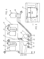
- - la figure 1 est une vue de face de l'appareil conforme à l'invention ;
- - la figure 2 est une vue de dessus de l'appareil de l'invention, capot de protection relevé ;
- - la figure 3 représente un dispositif d'étanchéité de la porte de l'appareil,
- - la figure 4 représente le schéma pneumatique de l'appareil.
- - Figure 1 is a front view of the apparatus according to the invention;
- - Figure 2 is a top view of the apparatus of the invention, protective cover raised;
- FIG. 3 represents a device for sealing the door of the appliance,
- - Figure 4 shows the pneumatic diagram of the device.
Le principe de base consiste à nettoyer automatiquement une ou plusieurs pièces à main ou turbines. Dans ce qui suit, on décrira un appareil conformé pour trois pièces à main et une turbine, mais il doit être compris que ceci n'est nullement limitatif.The basic principle consists in automatically cleaning one or more handpieces or turbines. In what follows, we will describe a device shaped for three handpieces and a turbine, but it should be understood that this is in no way limiting.
Selon l'invention, on fait passer à l'intérieur des pièces à nettoyer, avec rotation des axes intérieurs, plusieurs fluides de manière séquentielle tels que par exemple, à titre indicatif :
- - de l'eau pendant une durée de 18 à 100 secondes ;
- - du liquide désinfectant pendant une durée de 18 à 100 secondes ;
- - de l'air, pour sécher, pendant une durée de 18 à 100 secondes ;
- - de l'huile de lubrification, pendant une durée de 27 à 50 secondes.
- - water for a period of 18 to 100 seconds;
- - disinfectant liquid for a period of 18 to 100 seconds;
- - air, to dry, for a period of 18 to 100 seconds;
- - lubricating oil, for a period of 27 to 50 seconds.
A la fin de ce cycle, les pièces sont nettoyées, sèches, désinfectées, lubrifiées et prêtes à être utilisées.At the end of this cycle, the parts are cleaned, dried, disinfected, lubricated and ready to use.
On se réfère maintenant à la figure 1.We now refer to Figure 1.
L'appareil selon l'invention se présente sous la forme d'un caisson (1) déterminant intérieurement une chambre (2) fermée frontalement par une porte (3) articulée par exemple horizontalement sur le caisson (1).The apparatus according to the invention is in the form of a box (1) internally determining a chamber (2) closed frontally by a door (3) articulated for example horizontally on the box (1).
A l'intérieur de cette chambre et à sa partie supérieure sont disposés trois nez (4,5,6) de moteurs dentaires standardisés sur lesquels peuvent s'accrocher de manière conventionelle, autant de pièces à main, non représentées. Un quatrième nez (7) peut être prévu pour supporter une turbine.Inside this chamber and at its upper part are arranged three noses (4,5,6) of standardized dental motors on which can be hooked conventionally, as many handpieces, not shown. A fourth nose (7) can be provided to support a turbine.
Les accouplements sont tous en eux-mêmes connus et ne seront pas décrits en détail. Les nez supportant les turbines peuvent être de plusieurs types, en eux-mêmes connus, suivant la disposition d'arrivée ou de départ de l'air et du spray.The couplings are all known in themselves and will not be described in detail. The noses supporting the turbines can be of several types, known in themselves, depending on the arrangement of arrival or departure of air and spray.
Le nez de turbine (7) peut être changé en desserrant un, écrou moleté (8) accessible par l'extérieur, en fonction du type de turbine à nettoyer. Le nez est resserré par rotation inverse de l'écrou moleté.The turbine nose (7) can be changed by loosening a knurled nut (8) accessible from the outside, depending on the type of turbine to be cleaned. The nose is tightened by reverse rotation of the knurled nut.
Lorsque le nez (4,5,6) est destiné à recevoir un appareil à air (turbine), l'entrainement est assuré par un passage d'air, grâce à un connecteur spécifique en lui-même connu.When the nose (4,5,6) is intended to receive an air device (turbine), the drive is provided by an air passage, thanks to a specific connector known in itself.
Les nez de moteurs comportent de manière classique un axe avec entraineur, lesdits axes étant entrainés en rotation chacun par un pignon (9,10,11) visibles à la figure 2, qui engrènent l'un contre l'autre. Un pignon de commande (12) entrai- né par un moteur à air, non représenté, donne le mouvement à l'ensemble éventuellement avec un pignon satellite intermédiaire (13).The engine noses conventionally comprise an axis with a driver, said axes being driven in rotation each by a pinion (9,10,11) visible in FIG. 2, which mesh one against the other. A control pinion (12) driven by an air motor, not shown, gives movement to the assembly possibly with an intermediate satellite pinion (13).
On a décrit ci-dessus la cinématique de commande de mise en rotation simultanée des nez et donc des organes intérieurs des pièces qui y sont fixées, les opérations de nettoyage devant obligatoirement être effectuées sur les organes en mouvement pour être efficaces.The kinematics for controlling the simultaneous rotation of the noses and therefore of the internal organs of the parts which are fixed to them have been described above, the cleaning operations necessarily having to be carried out on the moving organs in order to be effective.
Il s'agit maintenant d'amener les différents fluides à traverser les pièces.It is now a question of bringing the various fluids through the rooms.
L'appareil selon l'invention comprend :
- - un réservoir d'eau (14) ;
- - un réservoir (15) de produits désinfectants liquides ou vapeurs ;
- - un réservoir d'huile (16).
- - a water tank (14);
- - a reservoir (15) of liquid or vapor disinfectant products;
- - an oil tank (16).
L'appareil reçoit de l'air sous pression par une conduite (30) avec un détendeur (17) réglable, avec manomètre (18). Par un ensemble d'électrovannes, l'air parvient dans chacun des réservoirs selon un rythme et un cycle réglables. Ce dispositif sera décrit ultérieurement.The apparatus receives pressurized air through a line (30) with an adjustable pressure regulator (17), with a pressure gauge (18). Through a set of solenoid valves, the air reaches each of the tanks at an adjustable rate and cycle. This device will be described later.
L'air ainsi admis pousse les fluides hors de leur réservoir respectif dans chacun des nez. Un clapet de sécurité ferme l'arrivée sur le nez si aucune pièce à main n'est montée sur celui-ci ; en montant une pièce à main sur un nez, l'arrière de celle-ci soulève le clapet et dégage l'ouverture permettant l'arrivée de fluide dans la douille arrière de la pièce à main.The air thus admitted pushes the fluids out of their respective reservoir in each of the noses. A safety valve closes the inlet on the nose if no handpiece is mounted on it; by mounting a handpiece on a nose, the back of it raises the valve and clears the opening allowing the arrival of fluid in the rear socket of the handpiece.
Après avoir traversé les pièces à nettoyer, les fluides arrivent dans la chambre (2) par la tête de la pièce à main et sont évacués par en tube (19).After passing through the parts to be cleaned, the fluids arrive in the chamber (2) through the head of the handpiece and are evacuated by tube (19).
Les électrovannes sont commandées, de manière connue, par une platine électronique, l'ensemble étant alimenté électriquement par un cordon (20).The solenoid valves are controlled, in a known manner, by an electronic circuit board, the assembly being electrically supplied by a cord (20).
Les différentes fonctions successives peuvent être visualisées sur la face avant sur un pupitre (21). Sur ce pupitre on trouve des voyants (22) indiquant le cycle en cours et des réglages de temps de cycle (23).The different successive functions can be viewed on the front panel on a console (21). On this console there are indicators (22) indicating the cycle in progress and cycle time settings (23).
La mise sous tension s'effectue par un interrupteur général (24), le cycle de nettoyage étant enclenché par un bouton poussoir (25).The power is switched on by a general switch (24), the cleaning cycle being triggered by a push button (25).
Une sécurité prévoit que le cycle de nettoyage ne peut démarrer que porte (3) fermée, l'ouverture de celle-ci coupant le circuit.A safety device provides that the cleaning cycle can only start with the door (3) closed, the opening of the latter cutting off the circuit.
Une autre sécurité prévoit que, lorsque le niveau d'un liquide est insuffisant, un voyant (26) de niveau s'allume ou s'éteint, coupant le cycle en cours.Another security provides that, when the level of a liquid is insufficient, a level indicator (26) lights up or goes out, cutting off the cycle in progress.
Le dosage des fluides s'effectue pour chaque réservoir par une vis (27,28,29), le réglage ne pouvant s'opérer que pendant le temps d'utilisation desdits liquides. Les réservoirs sont fermés par des bouchons de remplissage (32,33,34).The dosing of the fluids is carried out for each reservoir by a screw (27, 28, 29), the adjustment being able to take place only during the time of use of said liquids. The tanks are closed with filler caps (32,33,34).
Pour un dosage donné, le débit au regard de chaque liquide s'adapte automatiquement en fonction du nombre de nez utilisés.For a given dosage, the flow rate for each liquid is automatically adjusted according to the number of noses used.
L'appareil ne demande que peu d'entretien, les différentes interventions pouvant être effectuées en soulevant le capot supérieur (31) ou par l'arrière de l'appareil.The device requires little maintenance, the various interventions can be carried out by lifting the upper cover (31) or from the rear of the device.
A titre d'exemple, on peut prévoir des réglages de temps, dans les gammes et pour les fonctions suivantes :
- - lavage : de 18 à 100 secondes ;
- - séchage : de 35 à 120 secondes, avec possibilité d'air sec pulsé ou non ;
- - désinfectant : de 18 à 100 secondes ;
- - attente : de 35 à 120 secondes ;
- - séchage : de 18 à 100 secondes ;
- - graissage : de 27 à 50 secondes ;
- - extraction produits : de 5 à 25 secondes.
- - washing: from 18 to 100 seconds;
- - drying: from 35 to 120 seconds, with the possibility of pulsed dry air or not;
- - disinfectant: from 18 to 100 seconds;
- - wait: 35 to 120 seconds;
- - drying: from 18 to 100 seconds;
- - lubrication: from 27 to 50 seconds;
- - product extraction: from 5 to 25 seconds.
Un voyant de fin de cycle indique que celui-ci est terminé et que les pièces sont prêtes à être stérilisées.An end-of-cycle light indicates that the cycle is finished and that the parts are ready to be sterilized.
De manière avantageuse, on prévoira au niveau de la porte (3) un dispositif d'étanchéité constitué d'un tube creux (35) disposé à la périphérie de l'encadrement recevant la porte. Lorsque la porte est fermée et que l'appareil est mis en marche, le tube (35) est mis sous pression. Grâce au gonflement du tube ainsi obtenu, on réalise une étanchéité parfaite car le tube souple, sous l'effet de la pression, épouse parfaitement les formes du contour de la porte et de l'encadrement.Advantageously, there will be provided at the door (3) a sealing device consisting of a hollow tube (35) disposed at the periphery of the frame receiving the door. When the door is closed and the appliance is started, the tube (35) is pressurized. Thanks to the swelling of the tube thus obtained, a perfect seal is achieved because the flexible tube, under the effect of pressure, perfectly matches the shapes of the outline of the door and of the frame.
Ce dispositif d'étanchéité ne présente pas les défauts d'étanchéité des joints caoutchouc classiques, dus au vieillissement.This sealing device does not have the sealing defects of conventional rubber seals, due to aging.
Par ailleurs, il permet de réaliser une étanchéité optimale en dépit des légères surpressions qui peuvent naître dans la chambre de nettoyage lors du fonctionnement de l'appareil.Furthermore, it makes it possible to achieve an optimal seal despite the slight overpressures which may arise in the cleaning chamber during the operation of the device.
On s'attachera maintenant à décrire le fonctionnement pneumatique de l'appareil, en référence au schéma de la figure 4.We will now endeavor to describe the pneumatic operation of the device, with reference to the diagram in FIG. 4.
On y a représenté les différents réservoirs (14,15,16) précités.There are shown the various tanks (14,15,16) mentioned above.
Le système fonctionne avec de l'air sous pression selon des arrivées indiquées P, qui, par un ensemble d'électrovannes envoie l'air sous pression dans le réservoir de fluide sélectionné suivant la phase de travail de l'appareil. Le fluide est alors expulsé du réservoir pour être injecté vers la ou les pièces à main ou la turbine via le nez sur lequel lesdites pièces sont montées.The system works with pressurized air according to the indicated arrivals P, which, by a set of solenoid valves sends the pressurized air into the fluid reservoir selected according to the working phase of the device. The fluid is then expelled from the reservoir to be injected towards the handpiece (s) or the turbine via the nose on which said parts are mounted.
Avantageusement, les réservoirs (14,15) seront pourvus d'un dispositif (36,37) de génération d'un brouillard air-fluide permettant de régler le dosage de fluide.Advantageously, the tanks (14,15) will be provided with a device (36,37) for generating an air-fluid mist making it possible to adjust the dosage of fluid.
A chaque nez recevant un instrument est associée une électrovanne (38,39,40,41) permettant ou non le passage du brouillard d'eau ou de désinfectant, l'entrée de chacune de ces électrovannes étant reliée en un point commun (42,43) où arrivent à la fois le conduit (44) de brouillard d'eau et le conduit (45) de brouillard de désinfectant.Each nose receiving an instrument is associated with a solenoid valve (38,39,40,41) allowing or not the passage of the water mist or disinfectant, the inlet of each of these solenoid valves being connected at a common point (42, 43) where both the water mist conduit (44) and the disinfectant mist conduit (45) arrive.
En outre, à chaque nez est associé une arrivé d'huile (46,47,48,49) située en aval de l'électrovanne associée audit nez.In addition, each nose is associated with an oil inlet (46,47,48,49) located downstream of the solenoid valve associated with said nose.
Le dispositif de distribution d'huile (50) sera par exemple constitué d'un moyen connu assurant l'injection d'huile simultanément dans toutes les arrivées d'huile.The oil distribution device (50) will for example consist of a known means ensuring the injection of oil simultaneously into all the oil inlets.
En variante, le dispositif comportera un ensemble de commande assurant lors des phase de passage de brouillard d'eau, de brouillard de désinfectant ou d'huile un mode d'ouverture-fermeture des électrovannes associées aux nez selon un processus de chenillard.As a variant, the device will include a control assembly ensuring, during the water mist, disinfectant mist or oil mist passage phase, an opening-closing mode of the solenoid valves associated with the noses according to a chase process.
Concernant la structure des nez, on prévoiera que ceux-ci seront dépourvus de joints, ce qui assure ainsi par débordement le lavage et la désin- fectation des embouts et des tuyaux de spray des pièces à main.With regard to the structure of the noses, provision will be made for them to be free of seals, thereby ensuring overflowing the washing and disinfection of the nozzles and spray hoses of the handpieces.
Enfin, on prévoiera que les conduits d'huile aboutissent à la pièce à main à un niveau inférieur à l'entrée des canaux de spray de ladite pièce à main, ou des entrées correspondantes dans le nez supportant la pièce à main, ce qui évite d'introduire de l'huile dans les canaux de spray.Finally, provision will be made for the oil conduits to terminate in the handpiece at a level below the inlet of the spray channels of said handpiece, or of the corresponding inlets in the nose supporting the handpiece, which avoids introduce oil into the spray channels.
Claims (19)
Priority Applications (1)
| Application Number | Priority Date | Filing Date | Title |
|---|---|---|---|
| AT88470012T ATE82843T1 (en) | 1987-07-24 | 1988-06-22 | AUTOMATIC DEVICE FOR CLEANING DENTAL HANDPIECES. |
Applications Claiming Priority (2)
| Application Number | Priority Date | Filing Date | Title |
|---|---|---|---|
| FR8710654 | 1987-07-24 | ||
| FR8710654A FR2618357B1 (en) | 1987-07-24 | 1987-07-24 | AUTOMATIC APPARATUS FOR CLEANING DENTISTRY HANDPIECES |
Publications (4)
| Publication Number | Publication Date |
|---|---|
| EP0300945A2 EP0300945A2 (en) | 1989-01-25 |
| EP0300945A3 EP0300945A3 (en) | 1990-03-07 |
| EP0300945B1 true EP0300945B1 (en) | 1992-12-02 |
| EP0300945B2 EP0300945B2 (en) | 1998-01-07 |
Family
ID=9353624
Family Applications (1)
| Application Number | Title | Priority Date | Filing Date |
|---|---|---|---|
| EP88470012A Expired - Lifetime EP0300945B2 (en) | 1987-07-24 | 1988-06-22 | Automatic apparatus for cleaning dental handpieces |
Country Status (7)
| Country | Link |
|---|---|
| US (1) | US5057283A (en) |
| EP (1) | EP0300945B2 (en) |
| JP (1) | JP2743069B2 (en) |
| AT (1) | ATE82843T1 (en) |
| DE (1) | DE3876331T3 (en) |
| ES (1) | ES2036278T5 (en) |
| FR (1) | FR2618357B1 (en) |
Cited By (3)
| Publication number | Priority date | Publication date | Assignee | Title |
|---|---|---|---|---|
| DE4024171A1 (en) * | 1990-07-30 | 1992-02-06 | Kaltenbach & Voigt | METHOD FOR CARE OF PARTICULAR MEDICAL AND DENTAL INSTRUMENTS AND CARE FOR CARRYING OUT THIS METHOD |
| US6217329B1 (en) | 1999-03-26 | 2001-04-17 | Kaltenbach & Voigt Gmbh | Maintenance apparatus for a medical or dental handpiece |
| DE19913943B4 (en) * | 1999-03-26 | 2004-07-08 | Kaltenbach & Voigt Gmbh & Co. Kg | Care device for a medical or dental handpiece |
Families Citing this family (41)
| Publication number | Priority date | Publication date | Assignee | Title |
|---|---|---|---|---|
| FR2669563B1 (en) * | 1990-11-23 | 1993-01-08 | Micro Mega Sa | LIQUID DISPENSING DEVICE FOR A CLEANING, DISINFECTING AND LUBRICATING APPARATUS FOR DENTISTRY HANDPIECES. |
| WO1993017726A1 (en) * | 1992-03-13 | 1993-09-16 | American Sterilizer Company | Sterilization apparatus and method for multicomponent sterilant |
| DE4235713C2 (en) * | 1992-10-22 | 1995-11-16 | Kaltenbach & Voigt | Device for cleaning and / or disinfecting and / or maintaining medical or dental instruments |
| DE4244752C2 (en) * | 1992-10-22 | 1998-04-09 | Kaltenbach & Voigt | Device for cleaning and / or disinfecting and / or maintaining medical or dental processing instruments, in particular handpieces |
| DE4244753C2 (en) * | 1992-10-22 | 1998-04-09 | Kaltenbach & Voigt | Device for cleaning and / or disinfecting and / or maintaining medical or dental processing instruments, in particular handpieces |
| DE59310371D1 (en) * | 1992-10-22 | 2005-02-03 | Kaltenbach & Voigt | Device for cleaning and / or disinfecting and care of medical or dental instruments |
| DE4235699C2 (en) * | 1992-10-22 | 1998-05-07 | Kaltenbach & Voigt | Device for cleaning and / or disinfecting and caring for medical or dental handpieces |
| DE4323815C2 (en) * | 1993-07-15 | 1997-09-25 | Siemens Ag | Method and device for the hygienic preparation of medical, in particular dental, instruments |
| DE9310601U1 (en) * | 1993-07-15 | 1993-09-02 | Siemens Ag | Cassette for holding medical, in particular dental, instruments |
| US5533539A (en) * | 1993-07-15 | 1996-07-09 | Siemens Aktiengesellschaft | Apparatus for intensive cleaning of medical articles |
| DE4323816C2 (en) * | 1993-07-15 | 1996-02-08 | Siemens Ag | Method and device for intensive cleaning of medical, in particular dental, objects |
| GB2279873B (en) * | 1993-07-16 | 1996-11-13 | Stanley Clifford Jennings | Autoclave |
| US5348711A (en) * | 1993-07-21 | 1994-09-20 | Mdt Corporation | Dental handpiece sterilizer |
| US5520893A (en) * | 1993-09-29 | 1996-05-28 | Oxidyn, Incorporated | Apparatus with safety means for sterilizing articles with ozone |
| NL9400677A (en) * | 1994-04-27 | 1995-12-01 | Nl Mij Tot Bevordering Der Tan | Method and device for cleaning medical, paramedical and dental tools and lines. |
| JP2587001B2 (en) * | 1994-05-12 | 1997-03-05 | 株式会社ナカニシ | Dental handpiece maintenance device |
| US6368556B1 (en) | 1994-06-28 | 2002-04-09 | Akeda Dental A/S | Apparatus for operational cleaning of dental handpieces |
| DK0767633T3 (en) * | 1994-06-28 | 2003-07-07 | Akeda Dental As | Apparatus for operative cleaning of dental equipment |
| SE507213C2 (en) * | 1996-06-18 | 1998-04-27 | Tsp Medical Ab | Device for sterilizing instruments |
| US6302692B1 (en) * | 1999-12-23 | 2001-10-16 | Inter-Med, Llc. | Multi-valve dental handpiece supply reservoir |
| US6773685B2 (en) * | 2000-12-04 | 2004-08-10 | Peter Johansen | Apparatus for sterilizing dental handpieces |
| US6464498B2 (en) | 2001-03-27 | 2002-10-15 | Gary J. Pond | Irrigation and aspiration handpiece |
| FR2849767B1 (en) | 2003-01-15 | 2006-02-03 | Micro Mega Int Mfg Sa | IMPROVEMENT TO DENTAL INSTRUMENTS MECHANIZED IN PARTICULAR TO ENDODONTIC INSTRUMENTS AND HANDPIECE, SAID COUNTER-ANGLE ADAPTED TO RECEIVE REMOVABLELY FROM SUCH INSTRUMENTS |
| WO2005009271A1 (en) * | 2003-07-25 | 2005-02-03 | J. Morita Manufacturing Corporation | Maintenance device for medical hand piece |
| US8439677B2 (en) | 2003-07-25 | 2013-05-14 | J. Morita Manufacturing Corporation | Maintenance apparatus for medical hand piece |
| US7435398B2 (en) | 2004-11-12 | 2008-10-14 | Nitram Dental A/S | Apparatus for sterilizing dental hand pieces |
| EP1875878A1 (en) * | 2006-06-28 | 2008-01-09 | Favodent Karl Huber GmbH | Method of cleaning and desinfecting water supply pipes of dental instruments |
| EP1875879A1 (en) * | 2006-06-28 | 2008-01-09 | Favodent Karl Huber GmbH | Method for cleaning and disinfecting dental instruments |
| EP1952782B1 (en) * | 2007-02-05 | 2010-09-01 | Oro Clean Chemie AG | Adapter for cleaning medical instruments |
| JP4964616B2 (en) * | 2007-02-28 | 2012-07-04 | 株式会社ジーシー | Dental handpiece lubrication equipment |
| DE102007014213B4 (en) * | 2007-03-24 | 2009-04-30 | Sinepro Gmbh | Device for cleaning, disinfecting and lubricating English-language medical instruments |
| EP2236102B1 (en) * | 2009-03-03 | 2015-05-06 | W & H Dentalwerk Bürmoos GmbH | Cleaning or care device for cleaning or caring for a medical, in particular dental instrument |
| JP5302053B2 (en) * | 2009-03-06 | 2013-10-02 | 株式会社ナカニシ | Dental handpiece cleaning equipment |
| DE102009051620A1 (en) | 2009-11-02 | 2011-05-05 | Sycotec Gmbh & Co. Kg | Cleaning device for dental instrument, has medium pipe for connecting storage vessel with cleaning chamber, and measuring device determining amount of fluid in vessel, where measuring device has sensor designed as pressure sensor |
| EP2316375B1 (en) | 2009-11-02 | 2016-01-27 | Firma SycoTec GmbH & Co. KG | Cleaning device |
| FR2958852B1 (en) | 2010-04-14 | 2012-06-01 | Nnie Plus | AUTOMATIC DEVICE FOR DISINFECTING SURGICAL ENGINES. |
| DE102011001468B3 (en) * | 2011-03-22 | 2012-07-26 | Melag Ohg | Device useful for dosing predefinable amount of medium into target system comprises reservoir, dosing chamber connected with reservoir, first valve, device for producing negative pressure and second valve |
| EP2684807B1 (en) | 2012-07-10 | 2016-06-29 | W & H Dentalwerk Bürmoos GmbH | Container for a cleaning or maintaining agent |
| FR3067608B1 (en) * | 2017-06-19 | 2020-10-30 | Cdo Medical | AUTOMATIC THERMO-WASHER-LUBRICATOR |
| JP7164690B2 (en) * | 2018-06-01 | 2022-11-01 | 株式会社モリタ製作所 | Lubrication maintenance device for medical handpieces |
| JP6976220B2 (en) * | 2018-06-01 | 2021-12-08 | 株式会社モリタ製作所 | Refueling maintenance device for medical handpieces |
Family Cites Families (5)
| Publication number | Priority date | Publication date | Assignee | Title |
|---|---|---|---|---|
| US3371986A (en) * | 1964-02-24 | 1968-03-05 | American Sterilizer Co | Door and sealing arrangement therefor |
| IT1142212B (en) * | 1981-01-06 | 1986-10-08 | Pantomedical Grifo Di Ottavio | DEVICE FOR CLEANING DENTAL INSTRUMENTS IN PARTICULAR TURBINE DRILLS OR SIMILAR |
| DE3239549A1 (en) * | 1982-10-26 | 1984-04-26 | Dental-Festin GmbH & Co KG, 2730 Zeven | Device for cleaning dental instruments |
| JPS6058851A (en) * | 1983-09-10 | 1985-04-05 | 日新製鋼株式会社 | Manufacture of laminated metallic band |
| US4752444A (en) | 1985-12-09 | 1988-06-21 | Bowen Ltd. | Method for sterilizing a dental handpiece |
-
1987
- 1987-07-24 FR FR8710654A patent/FR2618357B1/en not_active Expired - Lifetime
-
1988
- 1988-06-22 EP EP88470012A patent/EP0300945B2/en not_active Expired - Lifetime
- 1988-06-22 AT AT88470012T patent/ATE82843T1/en not_active IP Right Cessation
- 1988-06-22 DE DE3876331T patent/DE3876331T3/en not_active Expired - Lifetime
- 1988-06-22 ES ES88470012T patent/ES2036278T5/en not_active Expired - Lifetime
- 1988-07-22 JP JP63181965A patent/JP2743069B2/en not_active Expired - Lifetime
- 1988-07-25 US US07/223,904 patent/US5057283A/en not_active Expired - Lifetime
Cited By (5)
| Publication number | Priority date | Publication date | Assignee | Title |
|---|---|---|---|---|
| DE4024171A1 (en) * | 1990-07-30 | 1992-02-06 | Kaltenbach & Voigt | METHOD FOR CARE OF PARTICULAR MEDICAL AND DENTAL INSTRUMENTS AND CARE FOR CARRYING OUT THIS METHOD |
| US6217329B1 (en) | 1999-03-26 | 2001-04-17 | Kaltenbach & Voigt Gmbh | Maintenance apparatus for a medical or dental handpiece |
| DE19913943B4 (en) * | 1999-03-26 | 2004-07-08 | Kaltenbach & Voigt Gmbh & Co. Kg | Care device for a medical or dental handpiece |
| DE19964383B4 (en) * | 1999-03-26 | 2005-09-22 | Kaltenbach & Voigt Gmbh & Co. Kg | Care device for a medical or dental handpiece |
| DE19913946B4 (en) * | 1999-03-26 | 2011-05-12 | Kaltenbach & Voigt Gmbh & Co. Kg | Care device for a medical or dental handpiece |
Also Published As
| Publication number | Publication date |
|---|---|
| ATE82843T1 (en) | 1992-12-15 |
| EP0300945B2 (en) | 1998-01-07 |
| EP0300945A2 (en) | 1989-01-25 |
| JP2743069B2 (en) | 1998-04-22 |
| ES2036278T5 (en) | 1998-03-01 |
| DE3876331D1 (en) | 1993-01-14 |
| DE3876331T2 (en) | 1993-05-27 |
| FR2618357A1 (en) | 1989-01-27 |
| DE3876331T3 (en) | 1998-05-20 |
| JPH021254A (en) | 1990-01-05 |
| EP0300945A3 (en) | 1990-03-07 |
| ES2036278T3 (en) | 1993-05-16 |
| US5057283A (en) | 1991-10-15 |
| FR2618357B1 (en) | 1990-02-23 |
Similar Documents
| Publication | Publication Date | Title |
|---|---|---|
| EP0300945B1 (en) | Automatic apparatus for cleaning dental handpieces | |
| US4990087A (en) | Dental tool maintenance apparatus and method | |
| EP2922622B1 (en) | Method and device for producing and dispensing a customised cosmetic product | |
| FR2490090A1 (en) | DEVICE FOR SUPPLYING OPERATING AGENTS, SUCH AS WATER AND AIR, TO HANDPIECES OF DENTISTRY | |
| US5318443A (en) | Method of flushing, disinfecting and lubricating a dental turbine handpiece | |
| US3037509A (en) | Apparatus for removing skin particles from a donor area and applying the particles to a recipient area | |
| US5157802A (en) | Pipe thread cleaning apparatus | |
| CN111134869A (en) | Scalpel cleaning device | |
| US7523512B1 (en) | System and method for cleaning restrooms | |
| EP1857185A1 (en) | Method and apparatus for supplying a spraying machine with small quantities of liquid product to be sprayed | |
| JPH07303661A (en) | Supporting equipment for dentist's hand tool operation | |
| CN216273028U (en) | Filling device of liquid pesticide | |
| US5800171A (en) | Exhaust control system for pneumatic devices and method | |
| CN110193503B (en) | Side mouth type branch artificial blood vessel | |
| WO2008000937A1 (en) | Apparatus for grinding and disinfecting waste, especially medical waste | |
| EP0832718A1 (en) | Control device for a surface contamination cleaning installation | |
| EP0006409B1 (en) | Device for controlling the filling and emptying of a column, column and demineralisation unit equipped with such a device | |
| JP3350420B2 (en) | CLEANING TANK CLEANING APPARATUS AND METHOD OF CLEANING THE SAME | |
| NO971457L (en) | Automated product drainage procedure for a packaging machine | |
| JP3559729B2 (en) | Method and apparatus for bleeding air from hydraulic equipment | |
| FR3121033A3 (en) | Device for lubricating and optionally cleaning and disinfecting dental handpieces | |
| US10722905B2 (en) | Paint roller cover cleaner | |
| JPH073084Y2 (en) | Pressure treatment device | |
| FR2744935A1 (en) | DEVICE AND PROCEDURE FOR CLEANING BY VERY STRONG SUCTION IN A WET ENVIRONMENT, PILOT BY A MICRO-PROCESSOR | |
| JPH0771401A (en) | Hydraulic pressure source device |
Legal Events
| Date | Code | Title | Description |
|---|---|---|---|
| PUAI | Public reference made under article 153(3) epc to a published international application that has entered the european phase |
Free format text: ORIGINAL CODE: 0009012 |
|
| AK | Designated contracting states |
Kind code of ref document: A2 Designated state(s): AT CH DE ES FR GB IT LI SE |
|
| 17P | Request for examination filed |
Effective date: 19890116 |
|
| PUAL | Search report despatched |
Free format text: ORIGINAL CODE: 0009013 |
|
| AK | Designated contracting states |
Kind code of ref document: A3 Designated state(s): AT CH DE ES FR GB IT LI SE |
|
| 17Q | First examination report despatched |
Effective date: 19920518 |
|
| GRAA | (expected) grant |
Free format text: ORIGINAL CODE: 0009210 |
|
| AK | Designated contracting states |
Kind code of ref document: B1 Designated state(s): AT CH DE ES FR GB IT LI SE |
|
| REF | Corresponds to: |
Ref document number: 82843 Country of ref document: AT Date of ref document: 19921215 Kind code of ref document: T |
|
| REF | Corresponds to: |
Ref document number: 3876331 Country of ref document: DE Date of ref document: 19930114 |
|
| ITF | It: translation for a ep patent filed |
Owner name: ST. ASSOC. MARIETTI & PIPPARELLI |
|
| GBT | Gb: translation of ep patent filed (gb section 77(6)(a)/1977) |
Effective date: 19930209 |
|
| REG | Reference to a national code |
Ref country code: ES Ref legal event code: FG2A Ref document number: 2036278 Country of ref document: ES Kind code of ref document: T3 |
|
| PLBI | Opposition filed |
Free format text: ORIGINAL CODE: 0009260 |
|
| 26 | Opposition filed |
Opponent name: DENTALWERK BUERMOOS GES. M.B.H. Effective date: 19930826 |
|
| EAL | Se: european patent in force in sweden |
Ref document number: 88470012.1 |
|
| APAC | Appeal dossier modified |
Free format text: ORIGINAL CODE: EPIDOS NOAPO |
|
| APAC | Appeal dossier modified |
Free format text: ORIGINAL CODE: EPIDOS NOAPO |
|
| APAC | Appeal dossier modified |
Free format text: ORIGINAL CODE: EPIDOS NOAPO |
|
| PLAW | Interlocutory decision in opposition |
Free format text: ORIGINAL CODE: EPIDOS IDOP |
|
| PUAH | Patent maintained in amended form |
Free format text: ORIGINAL CODE: 0009272 |
|
| STAA | Information on the status of an ep patent application or granted ep patent |
Free format text: STATUS: PATENT MAINTAINED AS AMENDED |
|
| ITF | It: translation for a ep patent filed |
Owner name: MARIETTI E GISLON S.R.L. |
|
| 27A | Patent maintained in amended form |
Effective date: 19980107 |
|
| AK | Designated contracting states |
Kind code of ref document: B2 Designated state(s): AT CH DE ES FR GB IT LI SE |
|
| REG | Reference to a national code |
Ref country code: CH Ref legal event code: AEN Free format text: MAINTIEN DU BREVET DONT L'ETENDUE A ETE MODIFIEE |
|
| REG | Reference to a national code |
Ref country code: ES Ref legal event code: DC2A Kind code of ref document: T5 Effective date: 19980203 |
|
| GBV | Gb: ep patent (uk) treated as always having been void in accordance with gb section 77(7)/1977 [no translation filed] |
Effective date: 19921202 |
|
| REG | Reference to a national code |
Ref country code: GB Ref legal event code: 710B |
|
| GBRJ | Gb: reinstated under rule 110(4) - alteration of time limits | ||
| GBTA | Gb: translation of amended ep patent filed (gb section 77(6)(b)/1977) |
Effective date: 19980907 |
|
| EUG | Se: european patent has lapsed | ||
| REG | Reference to a national code |
Ref country code: GB Ref legal event code: IF02 |
|
| REG | Reference to a national code |
Ref country code: FR Ref legal event code: TP |
|
| PGFP | Annual fee paid to national office [announced via postgrant information from national office to epo] |
Ref country code: ES Payment date: 20050728 Year of fee payment: 18 |
|
| APAH | Appeal reference modified |
Free format text: ORIGINAL CODE: EPIDOSCREFNO |
|
| REG | Reference to a national code |
Ref country code: FR Ref legal event code: CL |
|
| PGFP | Annual fee paid to national office [announced via postgrant information from national office to epo] |
Ref country code: SE Payment date: 20060607 Year of fee payment: 19 |
|
| PGFP | Annual fee paid to national office [announced via postgrant information from national office to epo] |
Ref country code: GB Payment date: 20060621 Year of fee payment: 19 |
|
| REG | Reference to a national code |
Ref country code: CH Ref legal event code: PFA Owner name: MICRO MEGA INTERNATIONAL MANUFACTURES S.A Free format text: MICRO-MEGA S.A.#5-12, RUE DU TUNNEL#BESANCON (FR) -TRANSFER TO- MICRO MEGA INTERNATIONAL MANUFACTURES S.A#5 RUE DU TUNNEL#25000 BESANCON (FR) Ref country code: CH Ref legal event code: NV Representative=s name: SPIERENBURG & PARTNER AG, PATENT- UND MARKENANWAEL |
|
| REG | Reference to a national code |
Ref country code: ES Ref legal event code: PC2A |
|
| PGFP | Annual fee paid to national office [announced via postgrant information from national office to epo] |
Ref country code: AT Payment date: 20070614 Year of fee payment: 20 Ref country code: CH Payment date: 20070614 Year of fee payment: 20 Ref country code: DE Payment date: 20070614 Year of fee payment: 20 |
|
| PGFP | Annual fee paid to national office [announced via postgrant information from national office to epo] |
Ref country code: IT Payment date: 20070625 Year of fee payment: 20 |
|
| EUG | Se: european patent has lapsed | ||
| GBPC | Gb: european patent ceased through non-payment of renewal fee |
Effective date: 20070622 |
|
| PGFP | Annual fee paid to national office [announced via postgrant information from national office to epo] |
Ref country code: FR Payment date: 20070621 Year of fee payment: 20 |
|
| PG25 | Lapsed in a contracting state [announced via postgrant information from national office to epo] |
Ref country code: GB Free format text: LAPSE BECAUSE OF NON-PAYMENT OF DUE FEES Effective date: 20070622 |
|
| PG25 | Lapsed in a contracting state [announced via postgrant information from national office to epo] |
Ref country code: SE Free format text: LAPSE BECAUSE OF NON-PAYMENT OF DUE FEES Effective date: 20070623 |
|
| REG | Reference to a national code |
Ref country code: CH Ref legal event code: PL |
|
| REG | Reference to a national code |
Ref country code: ES Ref legal event code: FD2A Effective date: 20070623 |
|
| PG25 | Lapsed in a contracting state [announced via postgrant information from national office to epo] |
Ref country code: ES Free format text: LAPSE BECAUSE OF NON-PAYMENT OF DUE FEES Effective date: 20070623 |