EP0300458A1 - Laser beam welding method for an inner cicumferential surface of a tube - Google Patents
Laser beam welding method for an inner cicumferential surface of a tube Download PDFInfo
- Publication number
- EP0300458A1 EP0300458A1 EP88111702A EP88111702A EP0300458A1 EP 0300458 A1 EP0300458 A1 EP 0300458A1 EP 88111702 A EP88111702 A EP 88111702A EP 88111702 A EP88111702 A EP 88111702A EP 0300458 A1 EP0300458 A1 EP 0300458A1
- Authority
- EP
- European Patent Office
- Prior art keywords
- tube
- laser beam
- rotary cylinder
- flexible tube
- work
- Prior art date
- Legal status (The legal status is an assumption and is not a legal conclusion. Google has not performed a legal analysis and makes no representation as to the accuracy of the status listed.)
- Granted
Links
- 238000003466 welding Methods 0.000 title claims abstract description 70
- 238000000034 method Methods 0.000 title description 7
- 230000009975 flexible effect Effects 0.000 claims abstract description 31
- 230000003287 optical effect Effects 0.000 claims abstract description 30
- 239000013307 optical fiber Substances 0.000 claims abstract description 17
- 230000008093 supporting effect Effects 0.000 claims abstract description 8
- 238000001816 cooling Methods 0.000 claims description 7
- 238000004140 cleaning Methods 0.000 claims description 5
- 239000007789 gas Substances 0.000 description 34
- 239000000835 fiber Substances 0.000 description 19
- XLYOFNOQVPJJNP-UHFFFAOYSA-N water Substances O XLYOFNOQVPJJNP-UHFFFAOYSA-N 0.000 description 16
- 239000000543 intermediate Substances 0.000 description 11
- 239000000463 material Substances 0.000 description 10
- JNDMLEXHDPKVFC-UHFFFAOYSA-N aluminum;oxygen(2-);yttrium(3+) Chemical compound [O-2].[O-2].[O-2].[Al+3].[Y+3] JNDMLEXHDPKVFC-UHFFFAOYSA-N 0.000 description 9
- 229910019901 yttrium aluminum garnet Inorganic materials 0.000 description 9
- 230000005540 biological transmission Effects 0.000 description 6
- XKRFYHLGVUSROY-UHFFFAOYSA-N Argon Chemical compound [Ar] XKRFYHLGVUSROY-UHFFFAOYSA-N 0.000 description 4
- 239000012530 fluid Substances 0.000 description 4
- 230000002950 deficient Effects 0.000 description 3
- 238000009434 installation Methods 0.000 description 3
- 241001052209 Cylinder Species 0.000 description 2
- 229910052786 argon Inorganic materials 0.000 description 2
- 238000004891 communication Methods 0.000 description 2
- 230000006835 compression Effects 0.000 description 2
- 238000007906 compression Methods 0.000 description 2
- 230000006866 deterioration Effects 0.000 description 2
- 238000010586 diagram Methods 0.000 description 2
- 230000002349 favourable effect Effects 0.000 description 2
- 238000007689 inspection Methods 0.000 description 2
- 230000001678 irradiating effect Effects 0.000 description 2
- 239000007788 liquid Substances 0.000 description 2
- 206010037660 Pyrexia Diseases 0.000 description 1
- 230000000903 blocking effect Effects 0.000 description 1
- 230000015556 catabolic process Effects 0.000 description 1
- 229910052729 chemical element Inorganic materials 0.000 description 1
- 238000011109 contamination Methods 0.000 description 1
- 238000006731 degradation reaction Methods 0.000 description 1
- 230000002542 deteriorative effect Effects 0.000 description 1
- -1 for example Substances 0.000 description 1
- 239000003517 fume Substances 0.000 description 1
- 239000001307 helium Substances 0.000 description 1
- 229910052734 helium Inorganic materials 0.000 description 1
- SWQJXJOGLNCZEY-UHFFFAOYSA-N helium atom Chemical compound [He] SWQJXJOGLNCZEY-UHFFFAOYSA-N 0.000 description 1
- 239000011261 inert gas Substances 0.000 description 1
- 229910052751 metal Inorganic materials 0.000 description 1
- 239000002184 metal Substances 0.000 description 1
- 238000013021 overheating Methods 0.000 description 1
- 238000005192 partition Methods 0.000 description 1
- 239000003208 petroleum Substances 0.000 description 1
- 238000010248 power generation Methods 0.000 description 1
- 238000003908 quality control method Methods 0.000 description 1
- 230000008439 repair process Effects 0.000 description 1
- 229910000679 solder Inorganic materials 0.000 description 1
- 239000000126 substance Substances 0.000 description 1
- 229920003051 synthetic elastomer Polymers 0.000 description 1
- 239000005061 synthetic rubber Substances 0.000 description 1
- 239000003496 welding fume Substances 0.000 description 1
Images


Classifications
-
- B—PERFORMING OPERATIONS; TRANSPORTING
- B23—MACHINE TOOLS; METAL-WORKING NOT OTHERWISE PROVIDED FOR
- B23K—SOLDERING OR UNSOLDERING; WELDING; CLADDING OR PLATING BY SOLDERING OR WELDING; CUTTING BY APPLYING HEAT LOCALLY, e.g. FLAME CUTTING; WORKING BY LASER BEAM
- B23K26/00—Working by laser beam, e.g. welding, cutting or boring
- B23K26/08—Devices involving relative movement between laser beam and workpiece
- B23K26/10—Devices involving relative movement between laser beam and workpiece using a fixed support, i.e. involving moving the laser beam
- B23K26/103—Devices involving relative movement between laser beam and workpiece using a fixed support, i.e. involving moving the laser beam the laser beam rotating around the fixed workpiece
- B23K26/106—Devices involving relative movement between laser beam and workpiece using a fixed support, i.e. involving moving the laser beam the laser beam rotating around the fixed workpiece inside the workpiece
-
- B—PERFORMING OPERATIONS; TRANSPORTING
- B23—MACHINE TOOLS; METAL-WORKING NOT OTHERWISE PROVIDED FOR
- B23K—SOLDERING OR UNSOLDERING; WELDING; CLADDING OR PLATING BY SOLDERING OR WELDING; CUTTING BY APPLYING HEAT LOCALLY, e.g. FLAME CUTTING; WORKING BY LASER BEAM
- B23K26/00—Working by laser beam, e.g. welding, cutting or boring
- B23K26/02—Positioning or observing the workpiece, e.g. with respect to the point of impact; Aligning, aiming or focusing the laser beam
- B23K26/06—Shaping the laser beam, e.g. by masks or multi-focusing
- B23K26/0665—Shaping the laser beam, e.g. by masks or multi-focusing by beam condensation on the workpiece, e.g. for focusing
-
- B—PERFORMING OPERATIONS; TRANSPORTING
- B23—MACHINE TOOLS; METAL-WORKING NOT OTHERWISE PROVIDED FOR
- B23K—SOLDERING OR UNSOLDERING; WELDING; CLADDING OR PLATING BY SOLDERING OR WELDING; CUTTING BY APPLYING HEAT LOCALLY, e.g. FLAME CUTTING; WORKING BY LASER BEAM
- B23K26/00—Working by laser beam, e.g. welding, cutting or boring
- B23K26/12—Working by laser beam, e.g. welding, cutting or boring in a special atmosphere, e.g. in an enclosure
- B23K26/123—Working by laser beam, e.g. welding, cutting or boring in a special atmosphere, e.g. in an enclosure in an atmosphere of particular gases
-
- B—PERFORMING OPERATIONS; TRANSPORTING
- B23—MACHINE TOOLS; METAL-WORKING NOT OTHERWISE PROVIDED FOR
- B23K—SOLDERING OR UNSOLDERING; WELDING; CLADDING OR PLATING BY SOLDERING OR WELDING; CUTTING BY APPLYING HEAT LOCALLY, e.g. FLAME CUTTING; WORKING BY LASER BEAM
- B23K26/00—Working by laser beam, e.g. welding, cutting or boring
- B23K26/14—Working by laser beam, e.g. welding, cutting or boring using a fluid stream, e.g. a jet of gas, in conjunction with the laser beam; Nozzles therefor
- B23K26/142—Working by laser beam, e.g. welding, cutting or boring using a fluid stream, e.g. a jet of gas, in conjunction with the laser beam; Nozzles therefor for the removal of by-products
-
- B—PERFORMING OPERATIONS; TRANSPORTING
- B23—MACHINE TOOLS; METAL-WORKING NOT OTHERWISE PROVIDED FOR
- B23K—SOLDERING OR UNSOLDERING; WELDING; CLADDING OR PLATING BY SOLDERING OR WELDING; CUTTING BY APPLYING HEAT LOCALLY, e.g. FLAME CUTTING; WORKING BY LASER BEAM
- B23K26/00—Working by laser beam, e.g. welding, cutting or boring
- B23K26/14—Working by laser beam, e.g. welding, cutting or boring using a fluid stream, e.g. a jet of gas, in conjunction with the laser beam; Nozzles therefor
- B23K26/1435—Working by laser beam, e.g. welding, cutting or boring using a fluid stream, e.g. a jet of gas, in conjunction with the laser beam; Nozzles therefor involving specially adapted flow control means
- B23K26/1438—Working by laser beam, e.g. welding, cutting or boring using a fluid stream, e.g. a jet of gas, in conjunction with the laser beam; Nozzles therefor involving specially adapted flow control means for directional control
-
- B—PERFORMING OPERATIONS; TRANSPORTING
- B23—MACHINE TOOLS; METAL-WORKING NOT OTHERWISE PROVIDED FOR
- B23K—SOLDERING OR UNSOLDERING; WELDING; CLADDING OR PLATING BY SOLDERING OR WELDING; CUTTING BY APPLYING HEAT LOCALLY, e.g. FLAME CUTTING; WORKING BY LASER BEAM
- B23K26/00—Working by laser beam, e.g. welding, cutting or boring
- B23K26/14—Working by laser beam, e.g. welding, cutting or boring using a fluid stream, e.g. a jet of gas, in conjunction with the laser beam; Nozzles therefor
- B23K26/1462—Nozzles; Features related to nozzles
- B23K26/1464—Supply to, or discharge from, nozzles of media, e.g. gas, powder, wire
- B23K26/1476—Features inside the nozzle for feeding the fluid stream through the nozzle
-
- B—PERFORMING OPERATIONS; TRANSPORTING
- B23—MACHINE TOOLS; METAL-WORKING NOT OTHERWISE PROVIDED FOR
- B23K—SOLDERING OR UNSOLDERING; WELDING; CLADDING OR PLATING BY SOLDERING OR WELDING; CUTTING BY APPLYING HEAT LOCALLY, e.g. FLAME CUTTING; WORKING BY LASER BEAM
- B23K26/00—Working by laser beam, e.g. welding, cutting or boring
- B23K26/20—Bonding
- B23K26/206—Laser sealing
-
- B—PERFORMING OPERATIONS; TRANSPORTING
- B23—MACHINE TOOLS; METAL-WORKING NOT OTHERWISE PROVIDED FOR
- B23K—SOLDERING OR UNSOLDERING; WELDING; CLADDING OR PLATING BY SOLDERING OR WELDING; CUTTING BY APPLYING HEAT LOCALLY, e.g. FLAME CUTTING; WORKING BY LASER BEAM
- B23K26/00—Working by laser beam, e.g. welding, cutting or boring
- B23K26/20—Bonding
- B23K26/21—Bonding by welding
- B23K26/24—Seam welding
- B23K26/28—Seam welding of curved planar seams
- B23K26/282—Seam welding of curved planar seams of tube sections
Definitions
- the present invention relates to an apparatus for performing circumferential seal welding between a thin tube such as a heat transfer tube in a heat-exchanger or the like and a mending sleeve inserted into that tube so as to internally cover a damaged location occurred in this thin tube.
- a steam generator which generates steam for rotating turbine blades has been known.
- a steam generator used in a pressurized water reactor is one kind of the multi-tube cylindrical type heat-exchangers in which secondary water is evaporated by heat-exchange with primary water heated in a nuclear reactor.
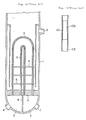
- a general internal structure of such steam generator is shown in Fig.
- High-temperature primary water fed from a nuclear reactor not shown enters one water chamber 3 through an inlet nozzle 7 communicating with that water chamber, then reaches the other water chamber 3 through the steam thin tubes 5, and flows back to the nuclear reactor through an outlet nozzle 8 communicating with the last-mentioned water chamber 3, and during the period when it passes through these steam thin tubes, it performs heat-exchange with secondary water for actuating a turbine which water is fed into the cylindrical shell 1 through a water feed nozzle 9.
- the secondary water that has become high-temperature steam in the above-described manner is adapted to be furnished to a steam turbine not shown from the top portion of the cylindrical shell 1.
- the expanded portion is work-hardened, hence in view of the necessity of making the protrusion of the mending sleeve bite into the inner circumferential surface of the heat transfer tube, the material of the mending sleeve must be sufficiently hard as compared to the material of the heat transfer tube, and thus there exist various restrictions.
- a laser beam welding apparatus for an inner circumferential surface of a tube, comprising an elongated flexible tube containing an optical fiber extended along the length thereof so as to transmit a laser beam, position detecting means disposed in the vicinity of the tip end of the flexible tube to determine relative positioning thereof with respect to a work tube in which the flexible tube is inserted, holding means provided with an expander and disposed adjacent to the position detecting means for holding the tip end of the flexible tube in the work tube, rotary drive means disposed closer to the tip end of the flexible tube than the holding means, a rotary cylinder connected to the rotary drive means to be rotated with respect to the flexible tube, guide means mounted on the rotary cylinder in a relatively rotatable manner with respect to the rotary cylinder and held in contact with the inner surface of the work tube for supporting the rotary cylinder in a concentric relation to the work tube, and an optical train arranged within the rotary cylinder for receiving a laser beam
- the above-featured laser beam welding apparatus wherein the rotary drive means is composed of an electric motor and a gear train.
- the first-featured laser beam welding apparatus wherein the rotary drive means is composed of a pneumatic rotary actuator.
- the above-featured laser beam welding apparatus further including a gas tube extended in and along the flexible tube, and a gas flow channel defined so as to conduct compressed gas to a welding point on the inner surface of the work tube.
- the first-featured or the last-feature laser beam welding apparatus further including another gas flow channel adapted to receive the compressed gas and extended to a reflector in the optical train for conducting a cooling and cleaning gas along the surfaces of optical elements in the optical train.
- the optical fiber is connected to a laser beam generator through a tapered fiber and a lens adapted to collect a laser beam emitted from the laser beam generator and transmit the beam to the optical fiber.
- the flexible tube inserted into a work tube is made to stop at a predetermined working location with the aid of the location detecting means, and the flexible tube is fixed to the work tube by making use of the holding means.
- the rotary cylinder is held in a concentric relation to the work tube by the guide means, and starting from this condition, the welding laser beam is irradiated onto the inner surface of the work tube via the optical train, at the same time the rotary cylinder is rotated by the rotary drive means, and thereby the welding laser beam is made to scan in an annular shape on the inner surface of the work tube.
- a laser beam is used for circumferential seal-welding between a work tube and a mending sleeve, excellent circumferential seal-welding has become possible without being influenced at all by the properties of materials of the mending sleeve and the work tube.
- the compressed gas flows through another gas flow channel and along the surfaces of the optical elements in the optical train up to the reflector at the extremal end for cooling the optical elements in the optical train to prevent overheating thereof, and also for cleaning these optical elements to prevent deterioration of their optical performance.
- a laser beam focused through a tapered fiber and a lens hence a laser beam having a high energy density can be obtained, and also the laser beam can be transmitted to the optical train by making use of an optical fiber having a small diameter.
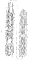
- FIG. 1 A cross-section of the structure of the laser beam welding apparatus is shown in Fig. 1, in which at the tip end of a flexible tube 12 to be inserted into a heat transfer tube 11 is integrally fitted by means of a lock metal 15 a connecting cylinder 14 having a position detector 13, which is of eddy current type in the illustrated embodiment, mounted on its outer circumferential surface.
- the above-mentioned position detector 13 is provided for the purpose of detecting the position of a mending sleeve 17 inserted into the heat transfer tube 11 and positioned so as to cover a defective location 16 of the heat transfer tube 11 or a header plate and a support plate not shown in a heat-exchanger, and also for the purpose of setting an irradiating position of a welding laser beam 18 as will be described later such as an Nd:YAG laser, a CO2 gas laser, etc.
- position detectors of other than eddy current type can be employed.
- an intermediate cylinder 20 covered by an air bag 19 made of synthetic rubber or the like having an appropriate mechanical strength and a sufficient expansibility, and in this intermediate cylinder 20 is formed an air feed/discharge hole 21 opening at the outer circumferential surface of the intermediate cylinder 20 for feeding compressed air into the space between the outer circumferential surface of the intermediate cylinder 20 and the inner circumferential surface of the cylindrical air bag 19.
- an air feed/discharge tube 22 which extends through the connecting cylinder 14 and the flexible tube 12 and communicates with an air feed/discharge device not shown, and when compressed air is fed into the air bag 19 through the air feed/discharge tube 22 and the air feed/discharge hole 21 by means of this air feed/discharge device, the air bag 19 expands and comes into tight contact with the inner surface of the heat transfer tube 11 as shown by double-dot chain lines in Fig. 1, so that the tip end portion of this welding apparatus can be fixedly held with respect to the heat transfer tube 11.
- a fixed cylinder 24 accommodating a drive motor 23 therein, and at the tip end portion of this fixed cylinder 24 is integrally fitted a support cylinder 27 which rotatably support a rotary cylinder 26 via a bearing 25.
- a transmission gear 29 rotatably supported by the support cylinder 27 and the fixed cylinder 24, is meshed with a drive gear 28 of the drive motor 23, and further, this transmission gear 29 is meshed with an inner gear 30 formed at the base end portion of the rotary cylinder 26. Accordingly, by actuating the drive motor 23, the rotary cylinder 26 is rotationally driven via the transmission gear 29.
- this rotary cylinder 26 On this rotary cylinder 26 are arranged a plurality of permanent magnets 31 at equal angular intervals in an annular array, and a rotational phase of the rotary cylinder 26 with respect to the support cylinder 27 can be detected as a result of relative movement between the permanent magnets 31 and rotation detecting coils 32 provided on the support cylinder 27 so as to oppose to these permanent magnets 31.
- Cables, not shown, connected to the drive motor 23 and the rotation detecting coils 32 extend through the intermediate cylinder 20, the connecting cylinder 14 and the flexible tube 12 and are connected to a control device not shown.
- This control device is also connected to a laser oscillator as will be described later, besides the aforementioned position detector 13 and the air feed/discharge device, so as to issue necessary control commands for these devices.
- a tip end portion of an optical fiber 33 which extends through the support cylinder 27, the fixed cylinder 24, the intermediate cylinder 20, the connecting cylinder 14 and the flexible tube 12 and connects with a laser oscillator not shown.
- a light focusing optical system 36 which focuses the welding laser beam 18 emitted in a diverging state from the emitting end surface of the optical fiber 33 towards a welding location 35 between the heat transfer tube 11 and the mending sleeve 17, as fixedly held within the rotary cylinder 26.
- a sleeve 39 is integrally fitted around the rotary cylinder 26, a channel 40 communicating with the above-mentioned beam irradiation hole 38 is formed between the sleeve 39 and the outer circumference of the rotary cylinder 26 as directed in the longitudinal direction of the rotary cylinder 26, a communication hole 42 communicating with the base end portion of this channel 40 and an annular groove 41 formed on the outer circumferential surface of the support cylinder 27, is formed in the rotary cylinder 26, and a gas feed tube 43 extending through the fixed cylinder, the intermediate cylinder 20, the connecting cylinder 14 and the flexible tube 12 and connected to a gas feed source not shown for feeding gas such as, for example, argon gas, is communicated with the aforementioned annular groove 41.
- a gas feed tube 43 extending through the fixed cylinder, the intermediate cylinder 20, the connecting cylinder 14 and the flexible tube 12 and connected to a gas feed source not shown for feeding gas such as, for example, argon gas, is communicated with the aforementioned annular groove 41.
- the gas fed through the gas feed tube 43 is ejected from the beam irradiation hole 38 to the space between the reflecting mirror 37 and the welding location 35, and thereby it can be preliminarily prevented that welding fume generated during a welding operation would adhere to the surfaces of the reflecting mirror 37 and the light focusing optical system 36 and these elements would be damaged by the welding laser beam 18.
- gas having a high molecular weight is favorable, but it will be also effective to use an inert gas such as argon gas, helium gas, etc. that is used as a shield gas in welding.
- a center shaft section 46 which supports via bushes 44 a roller supporting sleeve 45 in a relatively rotatable manner, and on the roller supporting sleeve 45 fitted around the center shaft section 46 are slidably fitted a pair of annular sliders 47.
- a pair of links 49 rotatably supporting a roller 48 which comes into contact with the inner surface of the heat transfer tube 11, are respectively secured to these sliders 47 via pins, and such sets of a roller 48 and links 49 are disposed in multiple (three sets in the illustrated embodiment) around the roller supporting sleeve 45 at an equal angular interval.
- the tip end portion of the laser beam welding apparatus is inserted into the heat transfer tube 11 within which a mending sleeve 17 has been preliminarily fitted, and after positioning has been done by means of the position detector 13 so that the beam irradiation hole 38 and the welding location 35 may oppose to each other, compressed air is fed into the air bag 19 to fixedly hold the intermediate cylinder 20 with respect to the heat transfer tube 11.
- the drive motor 23 is actuated to rotationally drive the rotary cylinder 26, at the same time the welding laser beam 18 is made to irradiate the welding location 35, and thereby circumferential seal welding between the heat transfer tube 11 and the mending sleeve 17 is carried out.
- the rotary cylinder 26 is held in a concentric relation to the heat transfer tube 11, the irradiating condition of the welding laser beam 18 to the welding location 35 is kept constant, and excellent circumferential seal welding becomes possible.
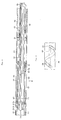
- a cross-sectional structure of the rotary drive means according to a second preferred embodiment of the present invention is illustrated in Figs. 2 and 3, Fig. 3 being a partial side view of the same structure as viewed in the direction of an arrow III in Fig. 2.
- two fluid feed/discharge tubes 52 and 53 are respectively connected to the inner space sections of the fixed cylinder 24 partitioned by this piston 51, and these fluid feed/discharge tubes 52 and 53 are extended through the intermediate cylinder 20 and a connecting cylinder and a flexible tube both not shown, and connected to a fluid feed/discharge device not shown.
- a pin 56 on which a roller 55 is rotatably mounted a straight guide hole 57 extending in the longitudinal direction of the support cylinder section 27 is formed in the support cylinder section 27 which is formed at the tip end portion of the fixed cylinder 24, also a spiral hole 58 is formed in the base end portion of the rotary cylinder 26, the roller 55 is engaged with this spiral hole 58, and the pin 56 could be also engaged with the guide hole 57.
- Fig. 4 is a longitudinal cross-section view showing the vicinity of a welding portion in a third preferred embodiment of the present invention.
- the section extending from the flexible tube and the connecting cylinder up to the rotary cylinder has a similar structure to that employed in the above-described first and second preferred embodiments.
- a channel 40' communicating with the communication hole 42 in the rotary cylinder 26 is provided, gas is fed into the rotary cylinder 26 so that it may be led to the beam irradiation hole 38 similarly to the first and second preferred embodiment above, and also the gas may be led from the channel 40′ through the light focusing optical system 36 to the reflecting mirror 37. Arrows in this figure indicate this flow of gas.
- the circumferences of the respective lenses in the light focusing optical system 36, respectively, have a notch 36′ at one location diametrically opposed to that of the adjacent lens. Consequently, the gas flows in a zig-zag manner along the surfaces of the respective lenses through these notches, and so, it can effectively cool the light focusing optical system 36 and also can achieve cleaning thereof.
- This cooling and cleaning gas flows further along the reflecting surface of the reflecting mirror 37 and along a spiral cooling fin 60 provided on the backside of the cooling mirror 37.
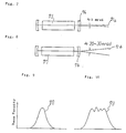
- a CO2 gas laser oscillator 75 and a light focusing mirror 76 are shown in Fig. 7.
- This CO2 gas laser oscillator can emit a laser beam 71a having a divergent angle approximately equal to 2 mrad.
- Fig. 8 are shown an Nd:YAG laser 77 and a light focusing mirror 76.
- This Nd:YAG laser can emit a laser beam 71b having a divergent angle approximately equal to 20 - 30 mrad.
- Fig. 5 shows a laser beam transmission system provided with a tapered fiber 72 for transmitting a laser beam emitted from a laser oscillator and passed through a light focusing lens, and also provided with a small-diameter fiber 73 for transmitting a laser beam 71 emitted from the tapered fiber 72 to a desired location.
- Fig. 6 shows another laser beam transmission system further provided with a large-diameter fiber 74 for transmitting a laser beam 71 emitted from an Nd:YAG laser oscillator (See 77 in Fig. 8) and passed through a light focusing lens (See 76 in Fig. 8) to the above-described tapered fiber 72.
- the above-described small-diameter fiber 73 is used as the optical fiber 33 shown in Figs. 1 to 4.
- a laser beam 71 emitted from a laser oscillator such as, for instance, the Nd:YAG laser oscillator 77 enters into the tapered fiber 71 via the light focusing lens 76, during the passage through the tapered fiber 72 the laser beam diameter is thinned, then the laser beam 71 enters into the small-diameter fiber 73, and then the laser beam is transmitted through the small-diameter fiber 73 to a desired welding position.
- a laser oscillator such as, for instance, the Nd:YAG laser oscillator 77
- the laser beam has its diameter reduced during the passage through the tapered fiber 72 to enter the small-diameter fiber and to be transmitted through the small-diameter fiber, and therefore, a laser beam having a high energy density can be transmitted to a welding position.
- a laser beam is used for circumferential seal-welding between a work tube and a mending sleeve, excellent circumferential seal-welding has become possible without being influenced at all by the properties of materials of the mending sleeve and the work tube.
- the present invention by making a gas flow pass through a welding point and/or an optical train (optical system), contamination of the optical system can be prevented and cooling of the optical system can be achieved. Hence, deterioration of the performance of the optical system can be prevented.
- the present invention makes it possible to transmit a laser beam having a high energy density to the welding position.
Abstract
Description
- The present invention relates to an apparatus for performing circumferential seal welding between a thin tube such as a heat transfer tube in a heat-exchanger or the like and a mending sleeve inserted into that tube so as to internally cover a damaged location occurred in this thin tube.
- Though it is quite natural that in steam prime motors or various electric power stations which directly made use of thermal energy, boilers as well as superheaters, feed water preheater, air preheater, condensor, etc. associated with boilers play a principal role, in various chemical industries such as the petrochemical industry and the petroleum industry, also a heat-exchanging system or a heat-exchanger is widely used in various steps of a process. Especially, a multi-tube cylindrical type heat-exchanger that is common as a large-sized heat-exchanger has a wide scope of utility, and it can well endure the use even in the high-temperature high-pressure system industry.
- Now, as one of the most important associated installations in a nuclear reactor for electric power generation, a steam generator which generates steam for rotating turbine blades has been known. In general, a steam generator used in a pressurized water reactor is one kind of the multi-tube cylindrical type heat-exchangers in which secondary water is evaporated by heat-exchange with primary water heated in a nuclear reactor. A general internal structure of such steam generator is shown in Fig. 11, in which a lower end portion of a vertical type cylindrical shell 1 is partitioned by a
header plate 2 to form a hemi-spherical water chamber 3, which is further divided into two chambers by means of avertical partition wall 4, and the opposite end ports of a large number of steamthin tubes 5 extending in a U-shape penetrate theheader plate 2 and are opening, respectively, in these twowater chambers 3. These steamthin tubes 5 are supported within the cylindrical shell 1 by the intermediary of a plurality ofsupport plates 6. High-temperature primary water fed from a nuclear reactor not shown enters onewater chamber 3 through aninlet nozzle 7 communicating with that water chamber, then reaches theother water chamber 3 through the steamthin tubes 5, and flows back to the nuclear reactor through an outlet nozzle 8 communicating with the last-mentionedwater chamber 3, and during the period when it passes through these steam thin tubes, it performs heat-exchange with secondary water for actuating a turbine which water is fed into the cylindrical shell 1 through awater feed nozzle 9. The secondary water that has become high-temperature steam in the above-described manner is adapted to be furnished to a steam turbine not shown from the top portion of the cylindrical shell 1. - Normally, in an installation relating to atomic energy, in addition to that the materials used in the installation are severely selected, quality control for the materials is carried out very strictly. In the above-described steam generator also, during its operation various inspections and repairs accompanying the inspections are conducted periodically, and in the event that anomaly of a steam thin tube should be found in one of the steam thin tubes, treatment for removing it from service as described in the following is effected. That is, for the purpose of preventing the high-pressure primary water from leaking out externally of the steam thin tube, blind plugs are fitted to the opposite end ports of the particular steam thin tube, seal welding is effected around the blind plugs, and thereby this steam thin tube is closed.
- According to the method of blocking heat transfer tubes for which damage has been discovered in a multi-tube cylindrical type heat-exchanger, there is a fear that as the number of damaged heat transfer tubes increases, degradation of the capability of a heat-exchanger may become remarkable and the efficiency of the entire plant also may be deteriorated. Therefore, an alternative method was proposed, in which in place of the blind plugs a
mending sleeve 102 is inserted into aheat transfer tube 103 so as to cover a damagedlocation 101 and the opposite end portions of thismending sleeve 102 are circumferentially seal-welded to theheat transfer tube 103 as shown in Fig. 12. - However, in the last-mentioned method, in the case where the material of the heat transfer tube is special material, it is necessary to use adequate high-temperature solder material, and so, in addition to difficulty in working, often the metallurgical structure of the heat transfer tube and the mending sleeve would be changed due to the high temperature upon welding. Hence, another method has been also proposed, in which in place of the aforementioned welding, an annular protrusion is formed around the outer circumferential surface of the mending sleeve, and air-tightness is maintained by expanding the mending sleeve to make the protrusion bite into the inner circumferential surface of the heat transfer tube. However, even according to the last-mentioned method, in the case where the heat transfer tube has been already expanded, the expanded portion is work-hardened, hence in view of the necessity of making the protrusion of the mending sleeve bite into the inner circumferential surface of the heat transfer tube, the material of the mending sleeve must be sufficiently hard as compared to the material of the heat transfer tube, and thus there exist various restrictions.
- It is therefore one object of the present invention to provide a laser beam welding apparatus for an inner circumferential surface of a tube, which can perform favorable circumferential seal welding between a work tube and a mending sleeve inserted into the work tube without being influenced by the properties of materials forming the work tube and the mending sleeve.
- According to one feature of the present invention, there is provided a laser beam welding apparatus for an inner circumferential surface of a tube, comprising an elongated flexible tube containing an optical fiber extended along the length thereof so as to transmit a laser beam, position detecting means disposed in the vicinity of the tip end of the flexible tube to determine relative positioning thereof with respect to a work tube in which the flexible tube is inserted, holding means provided with an expander and disposed adjacent to the position detecting means for holding the tip end of the flexible tube in the work tube, rotary drive means disposed closer to the tip end of the flexible tube than the holding means, a rotary cylinder connected to the rotary drive means to be rotated with respect to the flexible tube, guide means mounted on the rotary cylinder in a relatively rotatable manner with respect to the rotary cylinder and held in contact with the inner surface of the work tube for supporting the rotary cylinder in a concentric relation to the work tube, and an optical train arranged within the rotary cylinder for receiving a laser beam emitted from the optical fiber and focusing a reflected laser beam onto the inner surface of the work tube.
- According to another feature of the present invention, there is provided the above-featured laser beam welding apparatus, wherein the rotary drive means is composed of an electric motor and a gear train.
- According to still another feature of the present invention, there is provided the first-featured laser beam welding apparatus, wherein the rotary drive means is composed of a pneumatic rotary actuator.
- According to yet another feature of the present invention, there is provided the above-featured laser beam welding apparatus, further including a gas tube extended in and along the flexible tube, and a gas flow channel defined so as to conduct compressed gas to a welding point on the inner surface of the work tube.
- According to a further feature of the present invention, there is provided the first-featured or the last-feature laser beam welding apparatus, further including another gas flow channel adapted to receive the compressed gas and extended to a reflector in the optical train for conducting a cooling and cleaning gas along the surfaces of optical elements in the optical train.
- According to a still further feature of the present invention, there is provided the first-featured or the fourthly featured laser beam welding apparatus, wherein the optical fiber is connected to a laser beam generator through a tapered fiber and a lens adapted to collect a laser beam emitted from the laser beam generator and transmit the beam to the optical fiber.
- In operation, the flexible tube inserted into a work tube is made to stop at a predetermined working location with the aid of the location detecting means, and the flexible tube is fixed to the work tube by making use of the holding means. At this moment, the rotary cylinder is held in a concentric relation to the work tube by the guide means, and starting from this condition, the welding laser beam is irradiated onto the inner surface of the work tube via the optical train, at the same time the rotary cylinder is rotated by the rotary drive means, and thereby the welding laser beam is made to scan in an annular shape on the inner surface of the work tube.
- According to the present invention, since a laser beam is used for circumferential seal-welding between a work tube and a mending sleeve, excellent circumferential seal-welding has become possible without being influenced at all by the properties of materials of the mending sleeve and the work tube. In addition, there is no need to set a welding location at the tube end of the mending sleeve, and so, the positioning work for the welding location can be greatly simplified as compared to the welding apparatus in the prior art.
- Furthermore, in operation, since compressed gas is led to a welding point on the inner surface of the work tube through a gas flow channel, spatter and fume produced during welding can be prevented from adhering to the optical train and thus deteriorating optical performance thereof (for instance, a transmittivity of a lens, a reflecting power of a reflecting mirror, etc.). In addition, the compressed gas flows through another gas flow channel and along the surfaces of the optical elements in the optical train up to the reflector at the extremal end for cooling the optical elements in the optical train to prevent overheating thereof, and also for cleaning these optical elements to prevent deterioration of their optical performance. Still further, to the optical fiber extending within the flexible tube is transmitted a laser beam focused through a tapered fiber and a lens, hence a laser beam having a high energy density can be obtained, and also the laser beam can be transmitted to the optical train by making use of an optical fiber having a small diameter.
- The above-mentioned and other objects, features and advantages of the present invention will become more apparent by reference to the following description of preferred embodiments of the invention taken in conjunction with the accompanying drawings.
- In the accompanying drawings:
- Fig. 1 is a cross-section view showing a first preferred embodiment of the present invention;
- Fig. 2 is a cross-section view of a rotary drive section according to a second preferred embodiment of the present invention;
- Fig. 3 is a partial side view of the same rotary drive section as viewed in the direction of an arrow III;
- Fig. 4 is a cross-section view showing the vicinity of a welding section according to a third preferred embodiment of the present invention;
- Figs. 5 and 6 are schematic side views showing a fourth preferred embodiment of the present invention, Fig. 5 showing use of a tapered fiber, and Fig. 6 showing use of a tapered fiber and a large-diameter fiber;
- Fig. 7 is a schematic side view showing a CO₂ laser oscillator;
- Fig. 8 is a schematic side view showing an Nd:YAG (Yttrium Aluminum Garnet) laser oscillator;
- Fig. 9 is a diagram illustrating an energy density distribution in a laser beam generated from a CO₂ laser oscillator;
- Fig. 10 is a diagram illustrating an energy density distribution in a laser beam generated from an Nd:YAG laser oscillator;
- Fig. 11 is a cross-section view showing an outline of a steam generator; and
- Fig. 12 is a cross-section view showing the state of mending a heat transfer tube in a steam generator.
- In the following, description will be made on a first preferred embodiment of the present invention, in which the laser beam welding apparatus for an inner circumferential surface of a tube according to the present invention is applied to circumferential seal welding between a heat transfer tube in a heat-exchanger and a mending sleeve internally covering a defective location formed in this heat transfer tube. A cross-section of the structure of the laser beam welding apparatus is shown in Fig. 1, in which at the tip end of a
flexible tube 12 to be inserted into aheat transfer tube 11 is integrally fitted by means of a lock metal 15 a connectingcylinder 14 having aposition detector 13, which is of eddy current type in the illustrated embodiment, mounted on its outer circumferential surface. The above-mentionedposition detector 13 is provided for the purpose of detecting the position of amending sleeve 17 inserted into theheat transfer tube 11 and positioned so as to cover adefective location 16 of theheat transfer tube 11 or a header plate and a support plate not shown in a heat-exchanger, and also for the purpose of setting an irradiating position of awelding laser beam 18 as will be described later such as an Nd:YAG laser, a CO₂ gas laser, etc. As a matter of course, position detectors of other than eddy current type can be employed. - At the tip end of the aforementioned connecting
cylinder 14 is integrally fitted anintermediate cylinder 20 covered by anair bag 19 made of synthetic rubber or the like having an appropriate mechanical strength and a sufficient expansibility, and in thisintermediate cylinder 20 is formed an air feed/discharge hole 21 opening at the outer circumferential surface of theintermediate cylinder 20 for feeding compressed air into the space between the outer circumferential surface of theintermediate cylinder 20 and the inner circumferential surface of thecylindrical air bag 19. To this air feed/discharge hole 21 is connected an air feed/discharge tube 22 which extends through the connectingcylinder 14 and theflexible tube 12 and communicates with an air feed/discharge device not shown, and when compressed air is fed into theair bag 19 through the air feed/discharge tube 22 and the air feed/discharge hole 21 by means of this air feed/discharge device, theair bag 19 expands and comes into tight contact with the inner surface of theheat transfer tube 11 as shown by double-dot chain lines in Fig. 1, so that the tip end portion of this welding apparatus can be fixedly held with respect to theheat transfer tube 11. It is to be noted that in place of compressed air, other gas or liquid could be employed, and in place of theair bag 19 used in the illustrated embodiment, it is possible to employ other well-known expanding type of holding means. Furthermore, the sequence of connection to theflexible tube 12 of these connectingcylinder 14 and theintermediate cylinder 20 could be reversed. - At the tip end of the above-described
intermediate cylinder 20 is integrally fitted a fixedcylinder 24 accommodating adrive motor 23 therein, and at the tip end portion of this fixedcylinder 24 is integrally fitted asupport cylinder 27 which rotatably support arotary cylinder 26 via abearing 25. Atransmission gear 29 rotatably supported by thesupport cylinder 27 and the fixedcylinder 24, is meshed with adrive gear 28 of thedrive motor 23, and further, thistransmission gear 29 is meshed with aninner gear 30 formed at the base end portion of therotary cylinder 26. Accordingly, by actuating thedrive motor 23, therotary cylinder 26 is rotationally driven via thetransmission gear 29. On thisrotary cylinder 26 are arranged a plurality ofpermanent magnets 31 at equal angular intervals in an annular array, and a rotational phase of therotary cylinder 26 with respect to thesupport cylinder 27 can be detected as a result of relative movement between thepermanent magnets 31 androtation detecting coils 32 provided on thesupport cylinder 27 so as to oppose to thesepermanent magnets 31. Cables, not shown, connected to thedrive motor 23 and therotation detecting coils 32 extend through theintermediate cylinder 20, the connectingcylinder 14 and theflexible tube 12 and are connected to a control device not shown. This control device is also connected to a laser oscillator as will be described later, besides theaforementioned position detector 13 and the air feed/discharge device, so as to issue necessary control commands for these devices. - At the center of the tip end portion of the
support cylinder 27 is fixedly secured a tip end portion of anoptical fiber 33 which extends through thesupport cylinder 27, the fixedcylinder 24, theintermediate cylinder 20, the connectingcylinder 14 and theflexible tube 12 and connects with a laser oscillator not shown. In front of the emittingend surface 34 of thisoptical fiber 33 which transmits awelding laser beam 18 issued from the laser oscillator, is disposed a light focusingoptical system 36 which focuses thewelding laser beam 18 emitted in a diverging state from the emitting end surface of theoptical fiber 33 towards awelding location 35 between theheat transfer tube 11 and themending sleeve 17, as fixedly held within therotary cylinder 26. In addition, a reflectingmirror 37 disposed in front of the light focusingoptical system 33 for leading thewelding laser beam 18 to the above-mentionedwelding location 35, is fixedly secured to therotary cylinder 26 in an inclined state with respect to the rotary axis of therotary cylinder 26, and in association with the reflectingmirror 37, in therotary cylinder 26 is formed abeam irradiation hole 38 for leading thewelding laser beam 18 reflected by the reflectingmirror 37 to thewelding location 35. - In addition, in the illustrated embodiment, a
sleeve 39 is integrally fitted around therotary cylinder 26, achannel 40 communicating with the above-mentionedbeam irradiation hole 38 is formed between thesleeve 39 and the outer circumference of therotary cylinder 26 as directed in the longitudinal direction of therotary cylinder 26, acommunication hole 42 communicating with the base end portion of thischannel 40 and anannular groove 41 formed on the outer circumferential surface of thesupport cylinder 27, is formed in therotary cylinder 26, and agas feed tube 43 extending through the fixed cylinder, theintermediate cylinder 20, the connectingcylinder 14 and theflexible tube 12 and connected to a gas feed source not shown for feeding gas such as, for example, argon gas, is communicated with the aforementionedannular groove 41. Thus, the gas fed through thegas feed tube 43 is ejected from thebeam irradiation hole 38 to the space between the reflectingmirror 37 and thewelding location 35, and thereby it can be preliminarily prevented that welding fume generated during a welding operation would adhere to the surfaces of the reflectingmirror 37 and the light focusingoptical system 36 and these elements would be damaged by thewelding laser beam 18. As the gas used in this case, gas having a high molecular weight is favorable, but it will be also effective to use an inert gas such as argon gas, helium gas, etc. that is used as a shield gas in welding. - At the tip end of the above-described
rotary cylinder 26 is integrally projected acenter shaft section 46 which supports via bushes 44 aroller supporting sleeve 45 in a relatively rotatable manner, and on theroller supporting sleeve 45 fitted around thecenter shaft section 46 are slidably fitted a pair ofannular sliders 47. A pair oflinks 49 rotatably supporting aroller 48 which comes into contact with the inner surface of theheat transfer tube 11, are respectively secured to thesesliders 47 via pins, and such sets of aroller 48 andlinks 49 are disposed in multiple (three sets in the illustrated embodiment) around theroller supporting sleeve 45 at an equal angular interval. Between the opposite end portions of theroller supporting sleeve 45 and thesliders 47 are respectively interposed compression springs 50, hence theroller 48 is automatically pushed against the inner surface of the heat transfer tube via thelinks 49 by the resilient force of these compression springs 50, and thereby therotary cylinder 26 can be held in a concentric relation to theheat transfer tube 11. It is to be noted that as the guide means, besides the above-described embodiment, any other means could be employed so long as it can hold the rotary cylinder in a concentric relation to the heat transfer tube. - In operation, the tip end portion of the laser beam welding apparatus according to the present invention is inserted into the
heat transfer tube 11 within which amending sleeve 17 has been preliminarily fitted, and after positioning has been done by means of theposition detector 13 so that thebeam irradiation hole 38 and thewelding location 35 may oppose to each other, compressed air is fed into theair bag 19 to fixedly hold theintermediate cylinder 20 with respect to theheat transfer tube 11. Then, thedrive motor 23 is actuated to rotationally drive therotary cylinder 26, at the same time thewelding laser beam 18 is made to irradiate thewelding location 35, and thereby circumferential seal welding between theheat transfer tube 11 and the mendingsleeve 17 is carried out. In this case, since therotary cylinder 26 is held in a concentric relation to theheat transfer tube 11, the irradiating condition of thewelding laser beam 18 to thewelding location 35 is kept constant, and excellent circumferential seal welding becomes possible. - It is to be noted that while it is necessary to set the
welding locations 35 at two locations on the respective portions of the mendingsleeve 17 on the opposite sides of the defective location of the heat transfer tube, in view of the laser beam welding, there is no need to set thewelding locations 35 at the tube ends of the mendingsleeve 17. - While the
drive motor 23 was used as rotary drive means in the above-described embodiment, a cross-sectional structure of the rotary drive means according to a second preferred embodiment of the present invention is illustrated in Figs. 2 and 3, Fig. 3 being a partial side view of the same structure as viewed in the direction of an arrow III in Fig. 2. - As shown in these figures, within the fixed
cylinder 24 is slidably fitted apiston 51, two fluid feed/discharge tubes cylinder 24 partitioned by thispiston 51, and these fluid feed/discharge tubes intermediate cylinder 20 and a connecting cylinder and a flexible tube both not shown, and connected to a fluid feed/discharge device not shown. At the tip end portion of apiston sleeve 54 is projected apin 56 on which aroller 55 is rotatably mounted, astraight guide hole 57 extending in the longitudinal direction of thesupport cylinder section 27 is formed in thesupport cylinder section 27 which is formed at the tip end portion of the fixedcylinder 24, also aspiral hole 58 is formed in the base end portion of therotary cylinder 26, theroller 55 is engaged with thisspiral hole 58, and thepin 56 could be also engaged with theguide hole 57. - In operation, under the illustrated condition, when pressurized liquid is fed to one fluid feed/
discharge tube 52, thepiston 51 moves leftwards as viewed in Fig. 2, hence thepin 56 and theroller 55 would reach the left end of theguide hole 57, and due to the fact that theroller 55 moves straightly along theguide hole 57 as held in thespiral hole 58, therotary cylinder 26 would rotate, for example, by one revolution. During this operation, since an axial force is exerted upon therotary cylinder 20, arotary bearing 59 andbushes rotary cylinder 20 and thesupport cylinder 56, so that smooth rotation can be realized thereby. - It is to be noted that in Fig. 2, component members having the same functions as those shown in Fig. 1 are given like reference numerals.
- Fig. 4 is a longitudinal cross-section view showing the vicinity of a welding portion in a third preferred embodiment of the present invention. In this embodiment, the section extending from the flexible tube and the connecting cylinder up to the rotary cylinder has a similar structure to that employed in the above-described first and second preferred embodiments. However, in this particular embodiment, as shown in Fig. 4, a channel 40' communicating with the
communication hole 42 in therotary cylinder 26 is provided, gas is fed into therotary cylinder 26 so that it may be led to thebeam irradiation hole 38 similarly to the first and second preferred embodiment above, and also the gas may be led from thechannel 40′ through the light focusingoptical system 36 to the reflectingmirror 37. Arrows in this figure indicate this flow of gas. The circumferences of the respective lenses in the light focusingoptical system 36, respectively, have anotch 36′ at one location diametrically opposed to that of the adjacent lens. Consequently, the gas flows in a zig-zag manner along the surfaces of the respective lenses through these notches, and so, it can effectively cool the light focusingoptical system 36 and also can achieve cleaning thereof. This cooling and cleaning gas flows further along the reflecting surface of the reflectingmirror 37 and along aspiral cooling fin 60 provided on the backside of thecooling mirror 37. - Now a fourth preferred embodiment of the present invention will be described. A CO₂
gas laser oscillator 75 and alight focusing mirror 76 are shown in Fig. 7. This CO₂ gas laser oscillator can emit a laser beam 71a having a divergent angle approximately equal to 2 mrad. In addition, in Fig. 8 are shown an Nd:YAG laser 77 and alight focusing mirror 76. This Nd:YAG laser can emit a laser beam 71b having a divergent angle approximately equal to 20 - 30 mrad. - In the case where the CO₂
gas laser oscillator 75 shown in Fig. 7 is of high power type, since the divergent angle of the laser beam 71a is small, a single mode as shown in Fig. 9 can be obtained. However, in the case of the Nd:YAG laser 77 shown in Fig. 8, even if it is of high power type, only a multi-mode a shown in Fig. 10 can be obtained because the divergent angle of the laser beam is large, and since the laser beam is poor in spatial coherency, despite of the fact that the wavelength of this laser beam is shorter than that of the CO₂gas laser oscillator 75, there was a problem that a laser beam having a high energy density equivalent to that of the CO₂ gas laser oscillator could not be obtained. - Taking into consideration the aforementioned problem in the prior art, according to this fourth preferred embodiment, a laser beam transmission system in the circumferential laser beam welding apparatus in a tube has been improved.
- Fig. 5 shows a laser beam transmission system provided with a tapered
fiber 72 for transmitting a laser beam emitted from a laser oscillator and passed through a light focusing lens, and also provided with a small-diameter fiber 73 for transmitting alaser beam 71 emitted from the taperedfiber 72 to a desired location. On the other hand, Fig. 6 shows another laser beam transmission system further provided with a large-diameter fiber 74 for transmitting alaser beam 71 emitted from an Nd:YAG laser oscillator (See 77 in Fig. 8) and passed through a light focusing lens (See 76 in Fig. 8) to the above-describedtapered fiber 72. The above-described small-diameter fiber 73 is used as theoptical fiber 33 shown in Figs. 1 to 4. - According to this preferred embodiment, a
laser beam 71 emitted from a laser oscillator such as, for instance, the Nd:YAG laser oscillator 77, enters into the taperedfiber 71 via thelight focusing lens 76, during the passage through the taperedfiber 72 the laser beam diameter is thinned, then thelaser beam 71 enters into the small-diameter fiber 73, and then the laser beam is transmitted through the small-diameter fiber 73 to a desired welding position. In this way, the laser beam has its diameter reduced during the passage through the taperedfiber 72 to enter the small-diameter fiber and to be transmitted through the small-diameter fiber, and therefore, a laser beam having a high energy density can be transmitted to a welding position. - According to the present invention, since a laser beam is used for circumferential seal-welding between a work tube and a mending sleeve, excellent circumferential seal-welding has become possible without being influenced at all by the properties of materials of the mending sleeve and the work tube. In addition, there is no need to set a welding location at the tube end of the mending sleeve, and so, the positioning work for the welding location can be greatly simplified as compared to the welding apparatus in the prior art.
- Furthermore, according to the present invention, by making a gas flow pass through a welding point and/or an optical train (optical system), contamination of the optical system can be prevented and cooling of the optical system can be achieved. Hence, deterioration of the performance of the optical system can be prevented.
- Still further, owing to the connection of the optical fiber to the laser beam generator by the intermediary of a tapered fiber and a lens, the present invention makes it possible to transmit a laser beam having a high energy density to the welding position.
- While a principle of the present invention has been described above in connection to preferred embodiments of the invention, it is intended that all matter contained in the above description and illustrated in the accompanying drawings shall be interpreted to be illustrative and not as a limitation to the scope of the invention.
Claims (6)
an elongated flexible tube containing an optical fiber extended along the length thereof so as to transmit a laser beam;
position detecting means disposed in the vicinity of the tip end of said flexible tube to determine relative positioning thereof with respect to a work tube in which said flexible tube is inserted;
holding means provided with an expander and disposed adjacent to said position detecting means for holding said tip end of the flexible tube in said work tube;
rotary drive means disposed closer to said tip end of the flexible tube than said holding means;
a rotary cylinder connected to said rotary drive means to be rotated with respect to said flexible tube;
guide means mounted on said rotary cylinder in a relatively rotatable manner with respect to said rotary cylinder and held in contact with the inner surface of said work tube for supporting said rotary cylinder in a concentric relation to said work tube; and
an optical train arranged within said rotary cylinder for receiving a laser beam emitted from said optical fiber and focusing a reflected laser beam onto the inner surface of said work tube.
Applications Claiming Priority (4)
| Application Number | Priority Date | Filing Date | Title |
|---|---|---|---|
| JP181960/87 | 1987-07-21 | ||
| JP62181960A JPH0745113B2 (en) | 1987-07-21 | 1987-07-21 | Laser welding method for pipe inner surface |
| JP183670/87 | 1987-07-24 | ||
| JP62183670A JPH0698507B2 (en) | 1987-07-24 | 1987-07-24 | Inner surface repair device |
Publications (2)
| Publication Number | Publication Date |
|---|---|
| EP0300458A1 true EP0300458A1 (en) | 1989-01-25 |
| EP0300458B1 EP0300458B1 (en) | 1991-12-18 |
Family
ID=26500935
Family Applications (1)
| Application Number | Title | Priority Date | Filing Date |
|---|---|---|---|
| EP88111702A Expired - Lifetime EP0300458B1 (en) | 1987-07-21 | 1988-07-20 | Laser beam welding method for an inner cicumferential surface of a tube |
Country Status (3)
| Country | Link |
|---|---|
| US (1) | US4839495A (en) |
| EP (1) | EP0300458B1 (en) |
| DE (1) | DE3866985D1 (en) |
Cited By (28)
| Publication number | Priority date | Publication date | Assignee | Title |
|---|---|---|---|---|
| DE3910098A1 (en) * | 1989-03-29 | 1990-10-04 | N U Tech Gmbh Inst Fuer Werkst | Method of welding pipes by means of a laser and apparatus for carrying out the method |
| EP0418170A1 (en) * | 1989-09-15 | 1991-03-20 | Electricite De France | Apparatus and process for welding work-pieces by means of a laser beam |
| EP0418519A2 (en) * | 1989-08-07 | 1991-03-27 | Mitsubishi Jukogyo Kabushiki Kaisha | Reflecting mirror for a laser beam and laserbeam welding apparatus including the same |
| EP0428734A1 (en) * | 1989-05-08 | 1991-05-29 | Fanuc Ltd. | Laser beam machining device |
| FR2656559A1 (en) * | 1989-12-28 | 1991-07-05 | Framatome Sa | METHOD FOR WORKING WITH LASER IN A TUBE, AND WORKING HEAD FOR ITS IMPLEMENTATION |
| FR2656558A1 (en) * | 1989-12-28 | 1991-07-05 | Framatome Sa | LASER WORKING PROCESS IN A TUBE. |
| WO1992003248A1 (en) * | 1990-08-17 | 1992-03-05 | Siemens Aktiengesellschaft | Device and process for laser-welding pipes |
| WO1992003249A1 (en) * | 1990-08-17 | 1992-03-05 | Siemens Aktiengesellschaft | Device and process for laser-welding a pipe |
| EP0474219A2 (en) * | 1990-09-04 | 1992-03-11 | Mitsubishi Jukogyo Kabushiki Kaisha | Laser beam welding apparatus using an ultrasonic motor |
| EP0494558A1 (en) * | 1991-01-11 | 1992-07-15 | Framatome | Laser working head and process |
| US5196671A (en) * | 1990-08-17 | 1993-03-23 | Siemens Aktiengesellschaft | Device and process for the laser welding of a tube |
| FR2698576A1 (en) * | 1992-11-30 | 1994-06-03 | Framatome Sa | Method and device for repairing a defective area of the wall of a metal part and in particular of a tubular part. |
| EP0642874A1 (en) * | 1993-09-13 | 1995-03-15 | Westinghouse Electric Corporation | System and method for welding an inner diameter of a first tubular member disposed in an inside diameter of a second tubular member |
| WO1996003250A1 (en) * | 1994-07-21 | 1996-02-08 | Westinghouse Electric Corporation | Improved direct tube repair process |
| US5789720A (en) * | 1992-12-30 | 1998-08-04 | Westinghouse Electric Corporation | Method of repairing a discontinuity on a tube by welding |
| EP1247878A1 (en) * | 2001-04-04 | 2002-10-09 | Bayerische Motoren Werke Aktiengesellschaft | Apparatus for powder coating by laser |
| EP1273382A1 (en) * | 2001-07-05 | 2003-01-08 | Snecma Moteurs | Miniaturised laser beam welding apparatus |
| WO2013117754A1 (en) * | 2012-02-10 | 2013-08-15 | Limo Patentverwaltung Gmbh & Co. Kg | Device for the laser processing of a surface of a workpiece or for the post-treatment of a coating on the outside or the inside of a workpiece |
| FR3041280A1 (en) * | 2015-09-23 | 2017-03-24 | Saipem Sa | METHOD OF ASSEMBLING TUBES BY LASER WELDING |
| US20180029154A1 (en) * | 2013-05-23 | 2018-02-01 | Crc-Evans Pipeline International, Inc. | Rotating welding system and methods |
| DE102017200080A1 (en) * | 2017-01-05 | 2018-07-05 | Volkswagen Aktiengesellschaft | Hollow shaft and non-rotating lens laser tool |
| US10480862B2 (en) | 2013-05-23 | 2019-11-19 | Crc-Evans Pipeline International, Inc. | Systems and methods for use in welding pipe segments of a pipeline |
| US10695876B2 (en) | 2013-05-23 | 2020-06-30 | Crc-Evans Pipeline International, Inc. | Self-powered welding systems and methods |
| US10828715B2 (en) | 2014-08-29 | 2020-11-10 | Crc-Evans Pipeline International, Inc. | System for welding |
| CN113145983A (en) * | 2021-05-14 | 2021-07-23 | 赤峰元泰铸件有限公司 | Build-up welding machine tool for inner wall of pipe |
| US11458571B2 (en) | 2016-07-01 | 2022-10-04 | Crc-Evans Pipeline International, Inc. | Systems and methods for use in welding pipe segments of a pipeline |
| US11660701B2 (en) | 2017-01-05 | 2023-05-30 | Volkswagen Aktiengesellschaft | Laser tool with a focus adjustment unit |
| US11767934B2 (en) | 2013-05-23 | 2023-09-26 | Crc-Evans Pipeline International, Inc. | Internally welded pipes |
Families Citing this family (28)
| Publication number | Priority date | Publication date | Assignee | Title |
|---|---|---|---|---|
| FR2649923B1 (en) * | 1989-06-28 | 1992-04-24 | Framatome Sa | WORKING TOOLS WITHIN A TUBULAR ELEMENT |
| FR2656557B1 (en) * | 1989-12-28 | 1992-05-07 | Framatome Sa | LASER WORKING HEAD WITHIN A TUBE. |
| US5066846A (en) * | 1990-06-26 | 1991-11-19 | Westinghouse Electric Corp. | System and method for laser welding the inner surface of heat exchanger tubes |
| US5182429A (en) * | 1991-05-23 | 1993-01-26 | Westinghouse Electric Corp. | System and method for laser welding the inner surface of a tube |
| JP3214074B2 (en) * | 1992-07-15 | 2001-10-02 | 石川島播磨重工業株式会社 | Laser irradiation torch |
| US5359172A (en) * | 1992-12-30 | 1994-10-25 | Westinghouse Electric Corporation | Direct tube repair by laser welding |
| US5514849A (en) * | 1993-02-17 | 1996-05-07 | Electric Power Research Institute, Inc. | Rotating apparatus for repairing damaged tubes |
| US5430270A (en) * | 1993-02-17 | 1995-07-04 | Electric Power Research Institute, Inc. | Method and apparatus for repairing damaged tubes |
| JPH0755987A (en) * | 1993-08-20 | 1995-03-03 | Hitachi Ltd | Incore inspection-repair device for reactor |
| US5667706A (en) * | 1996-05-03 | 1997-09-16 | Westinghouse Electric Corporation | Apparatus and method for laser welding the inner surface of a tube |
| DE102004038310A1 (en) * | 2004-08-05 | 2006-02-23 | Kuka Schweissanlagen Gmbh | Laser device and operating method |
| US20060042083A1 (en) * | 2004-08-27 | 2006-03-02 | Baker Martin C | Repair of turbines on wing |
| FR2876933B1 (en) * | 2004-10-25 | 2008-05-09 | Snecma Moteurs Sa | NOZZLE FOR DRILLING HEAD OR MACHINING WITH LASER BEAM |
| JP4988160B2 (en) * | 2005-02-08 | 2012-08-01 | 日産自動車株式会社 | Laser welding apparatus, laser welding system, and laser welding method |
| EP2148195A1 (en) * | 2005-07-07 | 2010-01-27 | Kabushiki Kaisha Toshiba | Laser-based apparatus for ultrasonic flaw detection |
| EP1908546A1 (en) * | 2006-10-05 | 2008-04-09 | Trumpf Laser- und Systemtechnik GmbH | Diffuse laser beam reflector ; Room separation and working room with laser processing system with such a laser beam reflector |
| EP2496379B1 (en) * | 2009-11-03 | 2017-01-04 | The Secretary, Department Of Atomic Energy, Govt. of India | Method of manufacturing niobium based superconducting radio frequency (scrf) cavities comprising niobium components by laser welding |
| DE102010027638B4 (en) * | 2010-07-19 | 2012-04-12 | Christoph Deininger | Apparatus for processing pipes by means of a laser beam |
| CN102179629A (en) * | 2011-03-21 | 2011-09-14 | 中国科学院力学研究所 | System for carrying out laser etching on internal wall of cylinder liner of internal combustion engine and processing method thereof |
| JP5814652B2 (en) * | 2011-06-22 | 2015-11-17 | 株式会社東芝 | Laser irradiation apparatus and laser irradiation method |
| ES2725228T3 (en) | 2012-11-07 | 2019-09-20 | Alfa Laval Corp Ab | Plate package and method of manufacturing a plate package |
| US10040141B2 (en) | 2013-05-23 | 2018-08-07 | Crc-Evans Pipeline International, Inc. | Laser controlled internal welding machine for a pipeline |
| US9821415B2 (en) | 2014-03-28 | 2017-11-21 | Crc-Evans Pipeline International, Inc. | Internal pipeline cooler |
| US10328523B2 (en) * | 2014-07-11 | 2019-06-25 | Rolls-Royce Corporation | Fluted additive manufacturing deposition head design |
| US11813671B2 (en) | 2020-01-27 | 2023-11-14 | Rolls-Royce Corporation | Microtextured nozzle for directed energy deposition with greater than 100 features per square millimeter |
| CN113385812B (en) * | 2021-05-31 | 2022-11-18 | 中国工程物理研究院材料研究所 | Self-fusion welding sealing method for laser end face of small-pipe-diameter thin-wall metal conduit coreless rod |
| CN113977084B (en) * | 2021-12-30 | 2022-09-06 | 电王精密电器(北京)有限公司 | Integrated laser welding head |
| GB2622441A (en) * | 2022-09-16 | 2024-03-20 | United Kingdom Atomic Energy Authority | A laser tool |
Citations (2)
| Publication number | Priority date | Publication date | Assignee | Title |
|---|---|---|---|---|
| FR2382970B3 (en) * | 1977-03-07 | 1980-02-15 | Boc Ltd | |
| US4578554A (en) * | 1984-04-30 | 1986-03-25 | Teledyne, Inc. | Laser welding apparatus |
Family Cites Families (6)
| Publication number | Priority date | Publication date | Assignee | Title |
|---|---|---|---|---|
| US3772496A (en) * | 1971-10-26 | 1973-11-13 | Western Electric Co | Methods of forming a conductive path using an oxygen plasma to reduce reflectivity prior to laser machining |
| GB1484724A (en) * | 1974-05-21 | 1977-09-01 | Jobling & Co James A | Cutting glass tubing |
| US4029932A (en) * | 1975-05-05 | 1977-06-14 | Holobeam, Inc. | Lined pipe, and method and apparatus for making same |
| JPS5641091A (en) * | 1979-09-11 | 1981-04-17 | Toshiba Corp | Welding method of pipe |
| JPS5691992A (en) * | 1979-12-26 | 1981-07-25 | Hitachi Ltd | Laser welding method and laser working head |
| JPS62104689A (en) * | 1984-02-29 | 1987-05-15 | エルパトロ−ニク・アクチエンゲゼルシヤフト | Device for laser-welding vertical edge of can cylindrical section |
-
1988
- 1988-07-20 EP EP88111702A patent/EP0300458B1/en not_active Expired - Lifetime
- 1988-07-20 DE DE8888111702T patent/DE3866985D1/en not_active Expired - Lifetime
- 1988-07-21 US US07/222,170 patent/US4839495A/en not_active Expired - Fee Related
Patent Citations (2)
| Publication number | Priority date | Publication date | Assignee | Title |
|---|---|---|---|---|
| FR2382970B3 (en) * | 1977-03-07 | 1980-02-15 | Boc Ltd | |
| US4578554A (en) * | 1984-04-30 | 1986-03-25 | Teledyne, Inc. | Laser welding apparatus |
Cited By (51)
| Publication number | Priority date | Publication date | Assignee | Title |
|---|---|---|---|---|
| DE3910098C2 (en) * | 1989-03-29 | 1998-09-10 | Siemens Ag | Process for welding pipes using a laser and device for carrying out the process |
| DE3910098A1 (en) * | 1989-03-29 | 1990-10-04 | N U Tech Gmbh Inst Fuer Werkst | Method of welding pipes by means of a laser and apparatus for carrying out the method |
| EP0428734A1 (en) * | 1989-05-08 | 1991-05-29 | Fanuc Ltd. | Laser beam machining device |
| EP0428734A4 (en) * | 1989-05-08 | 1992-02-24 | ||
| EP0418519A2 (en) * | 1989-08-07 | 1991-03-27 | Mitsubishi Jukogyo Kabushiki Kaisha | Reflecting mirror for a laser beam and laserbeam welding apparatus including the same |
| EP0418519A3 (en) * | 1989-08-07 | 1994-03-30 | Mitsubishi Heavy Ind Ltd | |
| EP0418170A1 (en) * | 1989-09-15 | 1991-03-20 | Electricite De France | Apparatus and process for welding work-pieces by means of a laser beam |
| FR2652025A1 (en) * | 1989-09-15 | 1991-03-22 | Electricite De France | APPARATUS AND METHOD FOR WELDING METAL PARTS BY LASER BEAM. |
| FR2656559A1 (en) * | 1989-12-28 | 1991-07-05 | Framatome Sa | METHOD FOR WORKING WITH LASER IN A TUBE, AND WORKING HEAD FOR ITS IMPLEMENTATION |
| EP0438940A2 (en) * | 1989-12-28 | 1991-07-31 | Framatome | Process and laser head for working in a tube |
| EP0438940A3 (en) * | 1989-12-28 | 1991-11-13 | Framatome | Process and laser head for working in a tube |
| US5117086A (en) * | 1989-12-28 | 1992-05-26 | Framatome | Process and head for laser working in a tube |
| EP0437998A1 (en) * | 1989-12-28 | 1991-07-24 | Framatome | Laser working head within a tube |
| FR2656558A1 (en) * | 1989-12-28 | 1991-07-05 | Framatome Sa | LASER WORKING PROCESS IN A TUBE. |
| US5227605A (en) * | 1989-12-28 | 1993-07-13 | Framatome | Process for laser working in a tube, and working head for carrying out such process |
| WO1992003248A1 (en) * | 1990-08-17 | 1992-03-05 | Siemens Aktiengesellschaft | Device and process for laser-welding pipes |
| US5196671A (en) * | 1990-08-17 | 1993-03-23 | Siemens Aktiengesellschaft | Device and process for the laser welding of a tube |
| US5179260A (en) * | 1990-08-17 | 1993-01-12 | Siemens Aktiengesellschaft | Device and process for the laser welding of a tube |
| WO1992003249A1 (en) * | 1990-08-17 | 1992-03-05 | Siemens Aktiengesellschaft | Device and process for laser-welding a pipe |
| EP0474219A3 (en) * | 1990-09-04 | 1992-07-01 | Mitsubishi Jukogyo Kabushiki Kaisha | Ultrasonic motor and laser beam welding apparatus using the same |
| US5218258A (en) * | 1990-09-04 | 1993-06-08 | Mitsubishi Jukogyo Kabushiki Kaisha | Ultrasonic motor and laser beam welding apparatus using the same |
| EP0474219A2 (en) * | 1990-09-04 | 1992-03-11 | Mitsubishi Jukogyo Kabushiki Kaisha | Laser beam welding apparatus using an ultrasonic motor |
| EP0494558A1 (en) * | 1991-01-11 | 1992-07-15 | Framatome | Laser working head and process |
| FR2671503A1 (en) * | 1991-01-11 | 1992-07-17 | Framatome Sa | LASER WORKING PROCESS AND HEAD. |
| US5221822A (en) * | 1991-01-11 | 1993-06-22 | Framatome | Laser working method and head |
| FR2698576A1 (en) * | 1992-11-30 | 1994-06-03 | Framatome Sa | Method and device for repairing a defective area of the wall of a metal part and in particular of a tubular part. |
| US5443201A (en) * | 1992-11-30 | 1995-08-22 | Framatome | Method and device for repairing a defective zone of the wall of a metal part and in particular of a tubular part |
| EP0600768A1 (en) * | 1992-11-30 | 1994-06-08 | Framatome | Method and device for the repair of a defective zone of a metallic piece and particularly of a tubular piece |
| US5789720A (en) * | 1992-12-30 | 1998-08-04 | Westinghouse Electric Corporation | Method of repairing a discontinuity on a tube by welding |
| EP0642874A1 (en) * | 1993-09-13 | 1995-03-15 | Westinghouse Electric Corporation | System and method for welding an inner diameter of a first tubular member disposed in an inside diameter of a second tubular member |
| WO1996003250A1 (en) * | 1994-07-21 | 1996-02-08 | Westinghouse Electric Corporation | Improved direct tube repair process |
| EP1247878A1 (en) * | 2001-04-04 | 2002-10-09 | Bayerische Motoren Werke Aktiengesellschaft | Apparatus for powder coating by laser |
| EP1273382A1 (en) * | 2001-07-05 | 2003-01-08 | Snecma Moteurs | Miniaturised laser beam welding apparatus |
| FR2826893A1 (en) * | 2001-07-05 | 2003-01-10 | Snecma Moteurs | MINIATURIZED LASER BEAM WELDING APPARATUS |
| WO2003004214A1 (en) * | 2001-07-05 | 2003-01-16 | Snecma Moteurs | Welding unit with miniaturised laser beam |
| US7038161B2 (en) | 2001-07-05 | 2006-05-02 | Snecma Moteurs | Welding unit with miniaturized laser beam |
| WO2013117754A1 (en) * | 2012-02-10 | 2013-08-15 | Limo Patentverwaltung Gmbh & Co. Kg | Device for the laser processing of a surface of a workpiece or for the post-treatment of a coating on the outside or the inside of a workpiece |
| US20180029154A1 (en) * | 2013-05-23 | 2018-02-01 | Crc-Evans Pipeline International, Inc. | Rotating welding system and methods |
| US11767934B2 (en) | 2013-05-23 | 2023-09-26 | Crc-Evans Pipeline International, Inc. | Internally welded pipes |
| US10480862B2 (en) | 2013-05-23 | 2019-11-19 | Crc-Evans Pipeline International, Inc. | Systems and methods for use in welding pipe segments of a pipeline |
| US11175099B2 (en) | 2013-05-23 | 2021-11-16 | Crc-Evans Pipeline International, Inc. | Systems and methods for use in welding pipe segments of a pipeline |
| US10589371B2 (en) * | 2013-05-23 | 2020-03-17 | Crc-Evans Pipeline International, Inc. | Rotating welding system and methods |
| US10695876B2 (en) | 2013-05-23 | 2020-06-30 | Crc-Evans Pipeline International, Inc. | Self-powered welding systems and methods |
| US10828715B2 (en) | 2014-08-29 | 2020-11-10 | Crc-Evans Pipeline International, Inc. | System for welding |
| US10562235B2 (en) | 2015-09-23 | 2020-02-18 | Saipem S.A. | Method for assembling tubular joining sleeve and a conduit lining tube by laser welding |
| FR3041280A1 (en) * | 2015-09-23 | 2017-03-24 | Saipem Sa | METHOD OF ASSEMBLING TUBES BY LASER WELDING |
| US11458571B2 (en) | 2016-07-01 | 2022-10-04 | Crc-Evans Pipeline International, Inc. | Systems and methods for use in welding pipe segments of a pipeline |
| US11623302B2 (en) | 2017-01-05 | 2023-04-11 | Volkswagen Aktiengesellschaft | Laser tool having a hollow shaft drive and non-rotating lens; method for setting the focal position of the laser beams in a laser tool |
| US11660701B2 (en) | 2017-01-05 | 2023-05-30 | Volkswagen Aktiengesellschaft | Laser tool with a focus adjustment unit |
| DE102017200080A1 (en) * | 2017-01-05 | 2018-07-05 | Volkswagen Aktiengesellschaft | Hollow shaft and non-rotating lens laser tool |
| CN113145983A (en) * | 2021-05-14 | 2021-07-23 | 赤峰元泰铸件有限公司 | Build-up welding machine tool for inner wall of pipe |
Also Published As
| Publication number | Publication date |
|---|---|
| US4839495A (en) | 1989-06-13 |
| EP0300458B1 (en) | 1991-12-18 |
| DE3866985D1 (en) | 1992-01-30 |
Similar Documents
| Publication | Publication Date | Title |
|---|---|---|
| US4839495A (en) | Laser beam welding apparatus for an inner circumferential surface of a tube | |
| EP0418519B1 (en) | Reflecting mirror for a laser beam and laserbeam welding apparatus including the same | |
| US5491317A (en) | System and method for laser welding an inner surface of a tubular member | |
| US5430270A (en) | Method and apparatus for repairing damaged tubes | |
| US4694136A (en) | Laser welding of a sleeve within a tube | |
| US5066846A (en) | System and method for laser welding the inner surface of heat exchanger tubes | |
| US4694137A (en) | Laser welding head for sleeve-to-tube welding | |
| EP0234721B1 (en) | Laser beam alignment and transport system | |
| EP0665080B1 (en) | System and method for laser welding an inner surface of a small diameter tubular member | |
| US5514849A (en) | Rotating apparatus for repairing damaged tubes | |
| US5667706A (en) | Apparatus and method for laser welding the inner surface of a tube | |
| JPH02151382A (en) | Method and device for welding bush to the inside of pipe by remote control in steam generator particularly in nuclear power station | |
| US5006268A (en) | Device for laser welding inside a tubular element | |
| JP3214074B2 (en) | Laser irradiation torch | |
| US5182429A (en) | System and method for laser welding the inner surface of a tube | |
| EP0238171B1 (en) | Laser welding head for sleeve-to-tube welding | |
| US3394442A (en) | Tube plugging apparatus | |
| HU210091B (en) | Welding apparatus and method for welding metal sleeve to metal tube | |
| JP2862255B2 (en) | Laser welding equipment for pipe inner peripheral surface | |
| JP2560652Y2 (en) | Laser welding equipment for inner peripheral surface of pipe | |
| JPH0698507B2 (en) | Inner surface repair device | |
| JPH0716770A (en) | Laser beam machine | |
| KR19980084011A (en) | Equipment used to repair and repair defective heat pipes of large heat exchangers | |
| JPS6333189A (en) | Laser deposition head for fine tubu | |
| JP2000084685A (en) | Laser beam cutting and weld equipment for piping |
Legal Events
| Date | Code | Title | Description |
|---|---|---|---|
| PUAI | Public reference made under article 153(3) epc to a published international application that has entered the european phase |
Free format text: ORIGINAL CODE: 0009012 |
|
| 17P | Request for examination filed |
Effective date: 19880817 |
|
| AK | Designated contracting states |
Kind code of ref document: A1 Designated state(s): DE FR |
|
| 17Q | First examination report despatched |
Effective date: 19900313 |
|
| GRAA | (expected) grant |
Free format text: ORIGINAL CODE: 0009210 |
|
| AK | Designated contracting states |
Kind code of ref document: B1 Designated state(s): DE FR |
|
| REF | Corresponds to: |
Ref document number: 3866985 Country of ref document: DE Date of ref document: 19920130 |
|
| ET | Fr: translation filed | ||
| PLBE | No opposition filed within time limit |
Free format text: ORIGINAL CODE: 0009261 |
|
| STAA | Information on the status of an ep patent application or granted ep patent |
Free format text: STATUS: NO OPPOSITION FILED WITHIN TIME LIMIT |
|
| 26N | No opposition filed | ||
| PGFP | Annual fee paid to national office [announced via postgrant information from national office to epo] |
Ref country code: FR Payment date: 19980709 Year of fee payment: 11 |
|
| PGFP | Annual fee paid to national office [announced via postgrant information from national office to epo] |
Ref country code: DE Payment date: 19980724 Year of fee payment: 11 |
|
| PG25 | Lapsed in a contracting state [announced via postgrant information from national office to epo] |
Ref country code: FR Free format text: THE PATENT HAS BEEN ANNULLED BY A DECISION OF A NATIONAL AUTHORITY Effective date: 19990731 |
|
| PG25 | Lapsed in a contracting state [announced via postgrant information from national office to epo] |
Ref country code: DE Free format text: LAPSE BECAUSE OF NON-PAYMENT OF DUE FEES Effective date: 20000503 |
|
| REG | Reference to a national code |
Ref country code: FR Ref legal event code: ST |