EP0299589B1 - Low profile vehicle parking apparatus - Google Patents
Low profile vehicle parking apparatus Download PDFInfo
- Publication number
- EP0299589B1 EP0299589B1 EP88301900A EP88301900A EP0299589B1 EP 0299589 B1 EP0299589 B1 EP 0299589B1 EP 88301900 A EP88301900 A EP 88301900A EP 88301900 A EP88301900 A EP 88301900A EP 0299589 B1 EP0299589 B1 EP 0299589B1
- Authority
- EP
- European Patent Office
- Prior art keywords
- piston
- stanchions
- pivotally connected
- parking
- cylinder
- Prior art date
- Legal status (The legal status is an assumption and is not a legal conclusion. Google has not performed a legal analysis and makes no representation as to the accuracy of the status listed.)
- Expired - Lifetime
Links
Images


Classifications
-
- E—FIXED CONSTRUCTIONS
- E04—BUILDING
- E04H—BUILDINGS OR LIKE STRUCTURES FOR PARTICULAR PURPOSES; SWIMMING OR SPLASH BATHS OR POOLS; MASTS; FENCING; TENTS OR CANOPIES, IN GENERAL
- E04H6/00—Buildings for parking cars, rolling-stock, aircraft, vessels or like vehicles, e.g. garages
- E04H6/02—Small garages, e.g. for one or two cars
- E04H6/06—Small garages, e.g. for one or two cars with means for shifting or lifting vehicles
-
- B—PERFORMING OPERATIONS; TRANSPORTING
- B66—HOISTING; LIFTING; HAULING
- B66F—HOISTING, LIFTING, HAULING OR PUSHING, NOT OTHERWISE PROVIDED FOR, e.g. DEVICES WHICH APPLY A LIFTING OR PUSHING FORCE DIRECTLY TO THE SURFACE OF A LOAD
- B66F7/00—Lifting frames, e.g. for lifting vehicles; Platform lifts
- B66F7/02—Lifting frames, e.g. for lifting vehicles; Platform lifts with platforms suspended from ropes, cables, or chains or screws and movable along pillars
- B66F7/04—Lifting frames, e.g. for lifting vehicles; Platform lifts with platforms suspended from ropes, cables, or chains or screws and movable along pillars hydraulically or pneumatically operated
Definitions
- the present invention relates to a vehicle parking apparatus.
- a vehicle parking apparatus is employed to enable two vehicles to be parked in a surface area that approximately corresponds to the area of a standard vehicle parking space. More particularly, the vehicle parking apparatus includes a platform onto which a first vehicle is driven. The apparatus then raises the platform and the vehicle thereon a sufficient distance to enable a second vehicle to be parked underneath.
- Vehicle parking apparatuses of this type are widely used in urban areas of the United States where the land available for parking vehicles is extremely limited and where property values and building costs are extremely high.
- prior art devices of this type have been employed in open parking lots in New York to approximately double the number of cars that can be parked.
- the parking problems are even more acute, and prior art vehicle parking devices are very widely used.
- U.S. Patent No. 4, 209,276 which issued to the applicant herein on June 24, 1980.
- the disclosure of U.S. Patent No. 4,209,276 is incorporated herein in its entirety by reference.
- the parking apparatus shown in U.S. Patent No. 4,209,276 includes a base having a pair of spaced apart upstanding stanchions extending therefrom. The stanchions are spaced from one another a sufficient distance to enable a vehicle to be driven therebetween.
- a pair of hydraulic piston and cylinder assemblies are rigidly mounted respectively to the stanchions so that the cylinders extend upwardly from the tops of the stanchions.
- the pistons within the cylinders are each connected via a piston rod which extends downwardly to a platform or ramp onto which the vehicle may be driven, the platform being movable along the stanchions under the action of the hydraulic piston and cylinder assemblies.
- the hydraulically actuated withdrawal of the pistons into the corresponding cylinders will lift the platform with the vehicle thereon a distance equal to the movement of the piston which must be sufficient to enable a second vehicle to be driven between the stanchions and under the platform.
- the apparatus shown in U.S. Patent No. 4,209,276 includes stabilizer bar linkages which extend from the base to the platform to stabilize the platform and to provide an even lifting of the vehicle.
- British Patent No. 2,051,004 Another prior art parking apparatus is shown in British Patent No. 2,051,004, which issued to Roshier on March 16, 1983.
- the apparatus shown in British Patent No. 2,051,004 is very similar to the prior art vehicle parking apparatus shown in the above described U.S. Patent No. 4,209,276.
- the apparatus shown in British Patent No. 2,051,004 includes a piston and cylinder assembly wherein the cylinder is mounted to the base adjacent the stanchion and wherein the piston is connected to a vertical member extending upwardly from the platform on which the vehicle is parked.
- the pushing movement of the piston from the cylinder acts through the vertical member to lift the platform on which the vehicle is supported a distance exactly equal to the movement of the piston.
- the apparatus shown in British Patent No. 2,051,004 has several deficiencies.
- the relatively slender piston rod remains substantially entirely exposed and under compression throughout the entire period that a vehicle is supported in an elevated condition on the platform.
- An uneven weight distribution can create moments in the piston rod with a likelihood or bending or buckling.
- the piston rod must have a relatively large cross section, thereby adding to the cost of the piston and cylinder assembly. Inadvertent contact with the piston rod can easily occur in the environment of the parking lot or garage, thus further increasing maintenance requirements.
- the piston rod would extend to a height beyond the platform by a distance equal to the length of the vertical member connecting the piston rod to the platform.
- the aim of the present invention is to provide an improved parking apparatus that can be used in many indoor parking locations.
- a vehicle parking apparatus comprising first and second substantially parallel spaced apart generally upstanding stanchions with a parking platform disposed generally intermediate said stanchions and movable relative thereto, first and second control arms are pivotally connected to fixed locations spaced from the stanchions, with first and second rocker arms pivotally connected at a first pivot location to each control arm respectively, each rocker arm being also pivotally connected at respective second pivot locations to the parking platform, and two piston and cylinder assemblies being provided, characterised in that one end of each piston and cylinder assembly is pivotally connected to a respective rocker arm at a location between said first and second pivot locations, whilst the other end of each piston and cylinder assembly is pivotally connected to a respective elevated further fixed location which is located remote from the said fixed locations, whereby the piston and cylinder assemblies are operative to move the rocker arms about their respective first pivot locations and to thus selectively raise or lower the parking platform.
- One embodiment of the present invention comprises a pair of stanchions extending rigidly upwardly from a base, and a vehicle parking platform which is movable along the stanchions.
- Articulated stabilizing bar assemblies extend from the parking platform to the base, each articulated stabilizing bar assembly comprising a rocker arm and a control arm which are articulated to one another. the rocker arm is further articulated to the parking platform, and the control arm is articulated to the base.
- each piston and cylinder assembly is pivotally attached to a stanchion remote from the base.
- these said other ends may be pivotally attached to some other further fixed location e.g. an adjacent ceiling or wall of a parking garage.
- each piston and cylinder assembly may be such that the maximum extension of the piston and cylinder assembly substantially corresponds to the alignment of the stabilizing bar assembly in the lowest position of the parking platform.
- the connection of each piston and cylinder assembly with the articulated stabilizing bar assembly may be such that the piston will be fully retracted within the cylinder when the stabilizing bar assembly is in the fully elevated position of the parking platform.
- the piston/piston rod may be in its desirable fully retracted position relative to the cylinder when it is doing its work of retaining the vehicle in an elevated condition relative to the base.
- the subject vehicle parking assembly achieves the desirable attribute of combining the vehicle lifting function with the vehicle stabilizing function.
- the lifting of the vehicle is carried out through the articulated stabilizing bar assembly to achieve a controlled lifting and stabilizing function simultaneously. This combination achieves substantially improved stabilization which is extremely important in view of the wide variations of vehicle weights and centres of gravity.
- the parking apparatus of the subject invention achieves the extremely desirable attribute of having a very low profile to enable the use of the parking apparatus within indoor parking facilities that previously could not accept such parking devices.
- the maximum height of the subject vehicle parking apparatus is substantially equal to the height of the stanchions.
- the subject apparatus with an elevated vehicle thereon assumes a maximum height of between approximately 9.5 feet and 10 feet.
- the vehicle parking apparatus of the subject invention is indicated generally by the numeral 10 in Figs. 1-4.
- the parking apparatus 10 includes a base 12 which comprises first and second longitudinally extending support legs 14 and 16 which are disposed in spaced parallel relationship to one another as shown in Fig. 1. More particularly, the distance between the longitudinally extending support legs 14 and 16 is selected to exceed the maximum anticipated width of any vehicle to be parked on the apparatus 10.
- the longitudinally extending support leg 14 includes opposed front and rear ends 18 and 20, while the longitudinally extending support leg 16 includes opposed front and rear ends 22 and 24.
- the length defined by the respective longitudinal support legs 14 and 16 typically will be selected to be slightly less than the overall length of a vehicle to be parked on the apparatus 10.
- the base 12 further includes a transverse support 26 which extends between and connects the respective longitudinal supports legs 14 and 16. More particularly, the transverse support 26 is rigidly joined to the longitudinal supports 14 and 16 at locations intermedaite the respective front ends 18 and 22 and rear ends 20 and 24 thereof respectively.
- the transverse support 26 is dimensioned and configured to have a low profile to permit a vehicle to be readily driven over the transverse support 26 and a slow speed.
- the parking apparatus 10 further includes a pair of upstanding stanchions 34 and 36 which are rigidly connected to and extend from the respective longitudinal support legs 14 and 16 of the base 12. More particularly, the stanchions 34 and 36 extend substantially perpendicularly from the longitudinal support legs 14 and 16. However, the ends 38 and 40 of the stanchions 34 and 36 remote from the longitudinal supports 14 and 16 are angled in a rearward direction. This rearward angle of ends 38 and 40 of the stanchions 34 and 36 ensures a proper rearward sloping of a vehicle elevated by the apparatus 10 as explained herein. Additionally, the stanchions 34 and 36 preferably are configured to define track means as explained in the above cited U.S. Patent No. 4,209,276, the disclosure of which is incorporated herein by reference.
- the parking apparatus 10 further comprises a parking platform 42 which is mounted for movement along the stanchions 34 and 36. More particularly, the parking platform 42 includes a pair of longitudinally extending side rails 44 and 46 respectively and a central plate 48. The central plate 48 defines the surface on which a vehicle is parked and supported for elevation by the apparatus 10.
- the parking platform 42 further comprises follower means 54 and 56 for positively engaging and facilitating movement of the parking platform 42 relative to the stanchions 34 and 36.
- the follower means 54 and 56 may comprise wheels which are dimensioned to positively engage corresponding channels in the stanchions 34 and 36 in the manner described in the above cited U.S. Patent No. 4,209,276.
- the follower means 54 and 56 are specifically adapted to follow the angled ends 38 and 40 of the stanchions 34 and 36 to permit a tilting of the platform 42 as it approaches its uppermost position.
- the parking platform 42 futhter includes latch means 58 mounted adjacent the side rail 46 as shown in Figs. 2-4.
- the latch means 58 is operative to engage a locking support 60 adjacent the top ends 40 of the stanchions 36.
- the latch means 58 is operative to mechanically engage the locking support 60 to keep the parking platform 42 in its elevated condition.
- the latch means 58 may be selectively released when a vehicle on the parking platform 42 is to be lowered.
- Similar latch means and locking supports may be provided adjacent the side rail 44.
- the low profile parking apparatus 10 further comprises articulated stabilizer bar assemblies 64 and 66 which contribute to the efficient and even lifting and lowering of the parking platform 42. More particularly, the articulated stabilizing bar assembly 64 extends between the side rail 54 and the longitudinal support 14, while the articulated stabilizer bar assembly 66 extends between the side rail 46 and the longitudinal support 16.
- the articulated stabilizer bar assembly 64 comprises a rocker arm 68 and a control arm 70 which are articulated to one another to pivot point 72.
- the rocker arm 68 is pivotally connected to the side rail 54, while the control arm 70 is pivotally connected to the longitudinal support 14 adjacent end 20 thereof.
- the articulated stabilizer bar assembly 66 comprises rocker arm 74 and control arm 76 which are articulated to one another at point 78.
- the rocker arm 74 is further pivotally connected to the side rail 46 at pivot point 80 as shown in Figs. 2-4, while the control arm 76 is pivotally connected to the longitudinal support 16 adjacent the rear end 24 thereof.
- the raising and lowering of the parking platform 42 is achieved by substantially identical piston/cylinder assemblies 84 and 86 shown in Fig. 1.
- the piston and cylinder assembly 84 extends from pivot point 88 adjacent the top end 38 of the stanchion 34 to pivot point 90 on rocker arm 68.
- the piston and cylinder assembly 86 extends from a pivot point 92 adjacent the top end 40 of the stanchion 36 to pivot point 94 on rocker arm 74.
- the piston and cylinder assemblies 84 and 86 undergo substantially identical simultaneous operation to raise and lower the parking platform 42. This operation is shown in greater detail in Figs. 2-4 which depict the side of apparatus 10 on which piston and cylinder assembly 86 is disposed.
- the piston and cylinder assembly 86 comprises a piston rod 98 slidably disposed within a hydraulic cylinder 100.
- the cylinder 100 is pivotally connected to the top end 40 of stanchion 36 at pivot point 92.
- the pistons rod 98 is pivotally connected to the rocker arm 74 at pivot point 94, which is located approximately midway along the length of the rocker arm 74.
- pivot point 80 The relative radial position of pivot points 80 and 94 with respect to pivot point 78 cause the pivot point 80 to move a greater distance than pivot point 94 as the rocker arm 74 moves through an arc around the pivot point 78. Thus, any movement of the piston 98 will cause a substantially greater movement of the pivot point 80.
- pivot point 80 is attached to the side rail 46 of parking platform 42 which in turn is movable along stanchion 36. Consequently, any movement of piston 98 will cause a substantially greater movement of the parking platform up or down along stanchions 34 and 36. The maximum extension of piston 98 will cause pivot point 80 and parking platform 42 to move completely down into proximity with longitudinal support 16 as shown in Fig. 3. In this condition, the parking platform 42 will be in a position to recieve a vehicle thereon.
- the vehicle will be raised by the retraction of the piston rod 98 into the cylinder 100 under appropriately applied hydraulic force.
- both the pivot point 80 and the pivot point 94 will advance upwardly.
- the pivot point 80 will move a substantially greater distance in view of the relative difference in distance of pivot points 80 and 94 from pivot point 78. Wheb the piston rod 98 achieves its fully retracted position in cylinder 96, the platform 42 will be in a fully raised position relative to the stanchion 34 as shown in Fig. 4.
- the parking apparatus 10 performs the lifting work during the pulling strokes of the piston and cylinder assemblies 84 and 86.
- the relative locations of the pivot points along the rocker arms 68 and 74 enables the piston and cylinder assemblies 84 and 86 to lift the parking platform a distance approximately twice the maximum movement of the respective piston rods.
- the linkage between the piston and cylinder assemblies 84 and 86 and the respective articulated stabilizer arms 64 and 66 enables the parking platform 42 to be raised to the required elevation by an apparatus that does not exceed the height of the stanchions 34 and 36.
- the lifting forces are applied through the same mechanisms that stabilize the parking platform 42.
- the piston and cylinder assemblies 84 and 86 are attached to the articulated stabilizer bar assemblies 64 and 66 and contribute to the stabilization of the parking platform 42.
- the parking apparatus 10 ensures a high degree of stabilization throughout the lifting process.
- the rocker arm 74 comprises a central beam 102 which is substantially rectangular in cross section, and a pair of flanges 104 and 106 securely attached to opposed longitudinal sides of the beam 102.
- the flanges 104 and 106 have a greater height than the beam 102 to define a longitudinally extending channel 108 between the flanges 104 and 106 and the beam 102.
- the flanges 104 and 106 are provided with generally circular apertures 110 and 112 respectively extending through portions thereof which define the channel 108.
- the piston rod 98 terminates at end 114 and also is provided with an aperture 116 extending therethrough.
- An appropriate fastening means such as bolt 118, extends through the apertures 110, 112 and 116 to securely but pivotally connect the piston rod 98 to the rocker arm 74.
- the flanges 104 and 106 contribute to the strength and stability of the rocker arm 74.
- the channel 108 defines an area into which portions of the piston rod 98 may rotate as the piston 98 approaches its fully retracted position corresponding to the maximum elevation of the parking platform 42.
- a low profile vehicle parking apparatus includes a base and a pair of upstanding stanchions and can be raised or lowered along the stanchions.
- a pair of articulated stabilizer bar assemblies extends between the base and the parking platform to provide staiblized movement of the parking platform.
- each articulated stabilizer bar assembly comprises a rocker arm pivotally connected to the parking platform and a control arm pivotally connected to both the base and the end of the rocker arm remote from the parking platform.
- Piston and cylinder assemblies are connected to the ends of the stanchions remote from the base and to the respective rocker arms.
- the full extension of the piston rods from the cylinders moves the parking platform into the fully lowered position, while the retraction of the piston rods into the cylinders raises the parking platform to its maximum elevation.
- the forces exerted by the piston and cylinder assemblies act through the articulated stabilizer bar assemblies to further enhance the stabilization.
- the positions of the piston and cylinder assemblies provide a desirably low profile for the vehicle parking apparatus.
- the cylinders can be pivotally connected to a further fixed location such as an adjacent ceiling or wall of the parking garage in which the apparatus is located.
Landscapes
- Engineering & Computer Science (AREA)
- Structural Engineering (AREA)
- Architecture (AREA)
- Life Sciences & Earth Sciences (AREA)
- Geology (AREA)
- Mechanical Engineering (AREA)
- Civil Engineering (AREA)
- Vehicle Body Suspensions (AREA)
- Vehicle Cleaning, Maintenance, Repair, Refitting, And Outriggers (AREA)
- Refuge Islands, Traffic Blockers, Or Guard Fence (AREA)
- Braking Systems And Boosters (AREA)
- Reciprocating, Oscillating Or Vibrating Motors (AREA)
- Control Of Multiple Motors (AREA)
- Forklifts And Lifting Vehicles (AREA)
Abstract
Description
- The present invention relates to a vehicle parking apparatus.
- A vehicle parking apparatus is employed to enable two vehicles to be parked in a surface area that approximately corresponds to the area of a standard vehicle parking space. More particularly, the vehicle parking apparatus includes a platform onto which a first vehicle is driven. The apparatus then raises the platform and the vehicle thereon a sufficient distance to enable a second vehicle to be parked underneath.
- Vehicle parking apparatuses of this type are widely used in urban areas of the United States where the land available for parking vehicles is extremely limited and where property values and building costs are extremely high. For example, prior art devices of this type have been employed in open parking lots in New York to approximately double the number of cars that can be parked. In many European, South American and Asian cities, the parking problems are even more acute, and prior art vehicle parking devices are very widely used.
- It is believed that parking problems in urban areas in both the United States and other countries will become worse as populations continue to increase, open spaces in urban areas become less available and vehicles become more prevalent.
- To date, the above described vehicle parking apparatus has been widely used in open vehicle parking lots and to a considerably lesser extent in vehicle parking garages. The lower usage of vehicle parking apparatuses in parking garages is partly attributable to the height requirements of the parking apparatus. For example, an extremely effective prior art vehicle parking apparatus is shown in U.S. Patent No. 4, 209,276 which issued to the applicant herein on June 24, 1980. The disclosure of U.S. Patent No. 4,209,276 is incorporated herein in its entirety by reference. The parking apparatus shown in U.S. Patent No. 4,209,276 includes a base having a pair of spaced apart upstanding stanchions extending therefrom. The stanchions are spaced from one another a sufficient distance to enable a vehicle to be driven therebetween. A pair of hydraulic piston and cylinder assemblies are rigidly mounted respectively to the stanchions so that the cylinders extend upwardly from the tops of the stanchions. The pistons within the cylinders are each connected via a piston rod which extends downwardly to a platform or ramp onto which the vehicle may be driven, the platform being movable along the stanchions under the action of the hydraulic piston and cylinder assemblies. Thus, the hydraulically actuated withdrawal of the pistons into the corresponding cylinders will lift the platform with the vehicle thereon a distance equal to the movement of the piston which must be sufficient to enable a second vehicle to be driven between the stanchions and under the platform. To ensure that the vehicle on the platform is elevated evenly despite the possibility of uneven weight distribution in the vehicle, the apparatus shown in U.S. Patent No. 4,209,276 includes stabilizer bar linkages which extend from the base to the platform to stabilize the platform and to provide an even lifting of the vehicle.
- Despite the many advantages of the vehicle parking apparatus shown in U.S. Patent No. 4,209,276, the apparatus defined by the stanchions and the large piston and cylinder assemblies extending up from the stanchions, occupies a total height of approximately 11'4", which exceeds the floor to ceiling height in many parking structures.
- Another prior art parking apparatus is shown in British Patent No. 2,051,004, which issued to Roshier on March 16, 1983. The apparatus shown in British Patent No. 2,051,004 is very similar to the prior art vehicle parking apparatus shown in the above described U.S. Patent No. 4,209,276. However, the apparatus shown in British Patent No. 2,051,004 includes a piston and cylinder assembly wherein the cylinder is mounted to the base adjacent the stanchion and wherein the piston is connected to a vertical member extending upwardly from the platform on which the vehicle is parked. Thus, the pushing movement of the piston from the cylinder acts through the vertical member to lift the platform on which the vehicle is supported a distance exactly equal to the movement of the piston. The apparatus shown in British Patent No. 2,051,004 has several deficiencies. In particular, it is generally considered undesirable to provide a piston/cylinder apparatus, such as this, wherein the work is done on the pushing movement of the piston. More particularly, the relatively slender piston rod remains substantially entirely exposed and under compression throughout the entire period that a vehicle is supported in an elevated condition on the platform. An uneven weight distribution can create moments in the piston rod with a likelihood or bending or buckling. To prevent buckling, the piston rod must have a relatively large cross section, thereby adding to the cost of the piston and cylinder assembly. Inadvertent contact with the piston rod can easily occur in the environment of the parking lot or garage, thus further increasing maintenance requirements. Additionally, in the elevated condition of the vehicle, the piston rod would extend to a height beyond the platform by a distance equal to the length of the vertical member connecting the piston rod to the platform.
- The aim of the present invention is to provide an improved parking apparatus that can be used in many indoor parking locations.
- According to the present invention there is provided a vehicle parking apparatus comprising first and second substantially parallel spaced apart generally upstanding stanchions with a parking platform disposed generally intermediate said stanchions and movable relative thereto, first and second control arms are pivotally connected to fixed locations spaced from the stanchions, with first and second rocker arms pivotally connected at a first pivot location to each control arm respectively, each rocker arm being also pivotally connected at respective second pivot locations to the parking platform, and two piston and cylinder assemblies being provided, characterised in that one end of each piston and cylinder assembly is pivotally connected to a respective rocker arm at a location between said first and second pivot locations, whilst the other end of each piston and cylinder assembly is pivotally connected to a respective elevated further fixed location which is located remote from the said fixed locations, whereby the piston and cylinder assemblies are operative to move the rocker arms about their respective first pivot locations and to thus selectively raise or lower the parking platform.
- One embodiment of the present invention comprises a pair of stanchions extending rigidly upwardly from a base, and a vehicle parking platform which is movable along the stanchions. Articulated stabilizing bar assemblies extend from the parking platform to the base, each articulated stabilizing bar assembly comprising a rocker arm and a control arm which are articulated to one another. the rocker arm is further articulated to the parking platform, and the control arm is articulated to the base.
- Preferably said other end of each piston and cylinder assembly is pivotally attached to a stanchion remote from the base. Alternatively however, these said other ends may be pivotally attached to some other further fixed location e.g. an adjacent ceiling or wall of a parking garage.
- The connection of each piston and cylinder assembly to an articulated stabilizing bar assembly i.e. to the rocker arm, may be such that the maximum extension of the piston and cylinder assembly substantially corresponds to the alignment of the stabilizing bar assembly in the lowest position of the parking platform. Conversely, the connection of each piston and cylinder assembly with the articulated stabilizing bar assembly may be such that the piston will be fully retracted within the cylinder when the stabilizing bar assembly is in the fully elevated position of the parking platform. Thus, the piston/piston rod may be in its desirable fully retracted position relative to the cylinder when it is doing its work of retaining the vehicle in an elevated condition relative to the base. Furthermore, the subject vehicle parking assembly achieves the desirable attribute of combining the vehicle lifting function with the vehicle stabilizing function. In particular, the lifting of the vehicle is carried out through the articulated stabilizing bar assembly to achieve a controlled lifting and stabilizing function simultaneously. This combination achieves substantially improved stabilization which is extremely important in view of the wide variations of vehicle weights and centres of gravity.
- The above described arrangement of pivotal connections enable a relatively small movement of the piston to achieve a relatively great movement of the parking platform. Consequently, the parking apparatus of the subject invention achieves the extremely desirable attribute of having a very low profile to enable the use of the parking apparatus within indoor parking facilities that previously could not accept such parking devices. More particularly, the maximum height of the subject vehicle parking apparatus is substantially equal to the height of the stanchions. Thus, the subject apparatus with an elevated vehicle thereon assumes a maximum height of between approximately 9.5 feet and 10 feet.
- A further advantage arises from the fact that the vehicle parking apparatus of the present invention can be designed to lift a vehicle on the pulling stroke of the piston and cylinder assemblies so that the piston rods are protected within the cylinders when supporting a vehicle on the raised parking platform. A still further advantage arises from the fact that the vehicle parking apparatus of the present invention effectively co-ordinates the lifting members with the stabilizing members to ensure an efficient and stable lifting movement within a low profile space envelope.
- The present invention will now be further described, by way of example, with reference to the accompanying drawings, in which:-
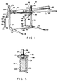
- Fig. 1 is a perspective view of the low profile vehicle parking apparatus of the subject invention;
- Fig. 2 is a side elevational view of the low profile vehicle parking apparatus of the subject invention;
- Fig. 3 is a side elevational view showing a portion of the vehicle parking apparatus in its lowest operational position;
- Fig. 4 is a side elevational view of a portion of the vehicle parking apparatus in its highest operational position; and
- Fig. 5 is a cross-section view taken along line 5-5 in Fig. 2.
- The vehicle parking apparatus of the subject invention is indicated generally by the
numeral 10 in Figs. 1-4. Theparking apparatus 10 includes abase 12 which comprises first and second longitudinally extendingsupport legs support legs apparatus 10. The longitudinally extendingsupport leg 14 includes opposed front andrear ends support leg 16 includes opposed front andrear ends longitudinal support legs apparatus 10. - The
base 12 further includes atransverse support 26 which extends between and connects the respectivelongitudinal supports legs transverse support 26 is rigidly joined to thelongitudinal supports rear ends transverse support 26 is dimensioned and configured to have a low profile to permit a vehicle to be readily driven over thetransverse support 26 and a slow speed. - The
parking apparatus 10 further includes a pair ofupstanding stanchions longitudinal support legs base 12. More particularly, thestanchions longitudinal support legs stanchions longitudinal supports ends stanchions apparatus 10 as explained herein. Additionally, thestanchions - The
parking apparatus 10 further comprises aparking platform 42 which is mounted for movement along thestanchions parking platform 42 includes a pair of longitudinally extendingside rails central plate 48. Thecentral plate 48 defines the surface on which a vehicle is parked and supported for elevation by theapparatus 10. Theparking platform 42 further comprises follower means 54 and 56 for positively engaging and facilitating movement of theparking platform 42 relative to thestanchions stanchions stanchions platform 42 as it approaches its uppermost position. - The
parking platform 42 futhter includes latch means 58 mounted adjacent theside rail 46 as shown in Figs. 2-4. The latch means 58 is operative to engage a lockingsupport 60 adjacent the top ends 40 of thestanchions 36. Thus, the latch means 58 is operative to mechanically engage the lockingsupport 60 to keep theparking platform 42 in its elevated condition. The latch means 58 may be selectively released when a vehicle on theparking platform 42 is to be lowered. Similar latch means and locking supports (not shown) may be provided adjacent theside rail 44. - The low
profile parking apparatus 10 further comprises articulatedstabilizer bar assemblies 64 and 66 which contribute to the efficient and even lifting and lowering of theparking platform 42. More particularly, the articulated stabilizing bar assembly 64 extends between theside rail 54 and thelongitudinal support 14, while the articulatedstabilizer bar assembly 66 extends between theside rail 46 and thelongitudinal support 16. - The articulated stabilizer bar assembly 64 comprises a
rocker arm 68 and acontrol arm 70 which are articulated to one another to pivotpoint 72. Therocker arm 68 is pivotally connected to theside rail 54, while thecontrol arm 70 is pivotally connected to thelongitudinal support 14adjacent end 20 thereof. In a similar manner, the articulatedstabilizer bar assembly 66 comprisesrocker arm 74 andcontrol arm 76 which are articulated to one another atpoint 78. Therocker arm 74 is further pivotally connected to theside rail 46 atpivot point 80 as shown in Figs. 2-4, while thecontrol arm 76 is pivotally connected to thelongitudinal support 16 adjacent therear end 24 thereof. - The raising and lowering of the
parking platform 42 is achieved by substantially identical piston/cylinder assemblies cylinder assembly 84 extends frompivot point 88 adjacent thetop end 38 of thestanchion 34 to pivotpoint 90 onrocker arm 68. The piston andcylinder assembly 86 extends from apivot point 92 adjacent thetop end 40 of thestanchion 36 to pivotpoint 94 onrocker arm 74. - The piston and
cylinder assemblies parking platform 42. This operation is shown in greater detail in Figs. 2-4 which depict the side ofapparatus 10 on which piston andcylinder assembly 86 is disposed. In particular, the piston andcylinder assembly 86 comprises apiston rod 98 slidably disposed within ahydraulic cylinder 100. Thecylinder 100 is pivotally connected to thetop end 40 ofstanchion 36 atpivot point 92. Similarly, thepistons rod 98 is pivotally connected to therocker arm 74 atpivot point 94, which is located approximately midway along the length of therocker arm 74. - The slidable advancement of the
piston rod 98 out of thecylinder 100 causes thepivot point 94 onrocker arm 74 to move downwardly. Conversely, the slidable retraction of thepiston rod 98 into thecylinder 100 causes thepivot point 94 on therocker arm 74 to advance upwardly. However, the movement of therocker arm 74 is limited and positively controlled by the pivotal connection to thecontrol arm 76 atpivot point 78. More particularly, the movement of thepivot point 94 under the action of thepiston 98 will cause a substantial pivotal movement of therocker arm 74 to pivotpoint 78. The relative radial position of pivot points 80 and 94 with respect to pivotpoint 78 cause thepivot point 80 to move a greater distance thanpivot point 94 as therocker arm 74 moves through an arc around thepivot point 78. Thus, any movement of thepiston 98 will cause a substantially greater movement of thepivot point 80. - Asnoted above, the
pivot point 80 is attached to theside rail 46 ofparking platform 42 which in turn is movable alongstanchion 36. Consequently, any movement ofpiston 98 will cause a substantially greater movement of the parking platform up or down alongstanchions piston 98 will causepivot point 80 andparking platform 42 to move completely down into proximity withlongitudinal support 16 as shown in Fig. 3. In this condition, theparking platform 42 will be in a position to recieve a vehicle thereon. - The vehicle will be raised by the retraction of the
piston rod 98 into thecylinder 100 under appropriately applied hydraulic force. As thepiston rod 98 is retracted, both thepivot point 80 and thepivot point 94 will advance upwardly. However, thepivot point 80 will move a substantially greater distance in view of the relative difference in distance of pivot points 80 and 94 frompivot point 78. Wheb thepiston rod 98 achieves its fully retracted position in cylinder 96, theplatform 42 will be in a fully raised position relative to thestanchion 34 as shown in Fig. 4. - As explained above, the
parking apparatus 10 performs the lifting work during the pulling strokes of the piston andcylinder assemblies rocker arms cylinder assemblies cylinder assemblies stabilizer arms 64 and 66 enables theparking platform 42 to be raised to the required elevation by an apparatus that does not exceed the height of thestanchions parking platform 42. In particular, the piston andcylinder assemblies stabilizer bar assemblies 64 and 66 and contribute to the stabilization of theparking platform 42. By pulling on the articulatedstabilizer bar assemblies 64 and 66, theparking apparatus 10 ensures a high degree of stabilization throughout the lifting process. - In the preferred embodiment, as illustrated in Fig. 5, the
rocker arm 74 comprises acentral beam 102 which is substantially rectangular in cross section, and a pair offlanges beam 102. Theflanges beam 102 to define alongitudinally extending channel 108 between theflanges beam 102. Theflanges circular apertures channel 108. Thepiston rod 98 terminates atend 114 and also is provided with anaperture 116 extending therethrough. An appropriate fastening means, such asbolt 118, extends through theapertures piston rod 98 to therocker arm 74. In this embodiment, theflanges rocker arm 74. Additionally, thechannel 108 defines an area into which portions of thepiston rod 98 may rotate as thepiston 98 approaches its fully retracted position corresponding to the maximum elevation of theparking platform 42. - In summary, a low profile vehicle parking apparatus is provided. The parking apparatus includes a base and a pair of upstanding stanchions and can be raised or lowered along the stanchions. A pair of articulated stabilizer bar assemblies extends between the base and the parking platform to provide staiblized movement of the parking platform. each articulated stabilizer bar assembly comprises a rocker arm pivotally connected to the parking platform and a control arm pivotally connected to both the base and the end of the rocker arm remote from the parking platform. Piston and cylinder assemblies are connected to the ends of the stanchions remote from the base and to the respective rocker arms. The full extension of the piston rods from the cylinders moves the parking platform into the fully lowered position, while the retraction of the piston rods into the cylinders raises the parking platform to its maximum elevation. The forces exerted by the piston and cylinder assemblies act through the articulated stabilizer bar assemblies to further enhance the stabilization. Furthermore, the positions of the piston and cylinder assemblies provide a desirably low profile for the vehicle parking apparatus. Alternatively, the cylinders can be pivotally connected to a further fixed location such as an adjacent ceiling or wall of the parking garage in which the apparatus is located.
- While the present invention has been described hereabove with respect to a preferred embodiment, it is apparent that various changes can be made without departing from the scope of the invention as defined by the appended claims.
Claims (6)
- A vehicle parking apparatus comprising first and second substantially parallel spaced apart generally upstanding stanchions (34,36) with a parking platform (42) disposed generally intermediate said stanchions (34,36) and movable relative thereto, first and second control arms (70,76) are pivotally connected to fixed locations (20,24) spaced from the stanchions (34,36), with first and second rocker arms (68, 74) pivotally connected at a first pivot location (72,78) to each control arm (70,76) respectively, each rocker arm (68,74) being also pivotally connected at respective second pivot locations (80) to the parking platform (42), and two piston and cylinder assemblies (84,86) being provided, characterised in that one end of each piston and cylinder assembly (84,86) is pivotally connected to a respective rocker arm (68,74) at a location (90,94) between said first and second pivot locations, whilst the other end of each piston and cylinder assembly (84,86) is pivotally connected to a respective elevated further fixed location (88,92) which is located remote from the said fixed locations (20,24), whereby the piston and cylinder assemblies (84,96) are operative to move the rocker arms (68,74) about their respective first pivot locations (72,78) and to thus selectively raise or lower the parking platform (42).
- Apparatus as claimed in claim 1, wherein said stanchions (34,36) are rigidly connected to a base (12) with said parking platform (42) being movable between a first position substantially adjacent said base (12) and a second position elevated from said base (12).
- Apparatus as claimed in claim 2, wherein the base (12) comprises first and second longitudinally extending support legs (14, 16) which are disposed in spaced parallel relationship to each other, and a transverse support (26) rigidly connected to and extending between said longitudinal support legs (14, 16), said stanchions (34, 36) being rigidly connected to said longitudinal support legs (14, 16).
- Apparatus as claimed in claim 3, wherein the fixed locations (20, 24) to which the control arms (70, 76) are each pivotally connected, are located respectively on the longitudinal support legs (14, 16) of the base (12) remote from the stanchions (34, 36).
- Apparatus as claimed in any one of claims 1 to 4, wherein the further fixed locations (88, 92) to which the piston and cylinder assemblies (84, 86) are pivotally attached, are located on said stanchions (34, 36) remote from said base (12).
- Apparatus as claimed in any one of claims 1 to 5, wherein each piston and cylinder assembly (84, 86) comprises a cylinder (100) with a piston slidably disposed therein, said cylinder (100) being pivotally connected to a stanchion (36), and said piston being pivotally connected to a rocker arm (74) by a piston rod (98).
Priority Applications (1)
| Application Number | Priority Date | Filing Date | Title |
|---|---|---|---|
| AT88301900T ATE89234T1 (en) | 1987-07-14 | 1988-03-04 | LOW PARKING DEVICE FOR MOTOR VEHICLES. |
Applications Claiming Priority (2)
| Application Number | Priority Date | Filing Date | Title |
|---|---|---|---|
| US07/072,861 US4772172A (en) | 1987-07-14 | 1987-07-14 | Low profile vehicle parking apparatus |
| US72861 | 1987-07-14 |
Publications (2)
| Publication Number | Publication Date |
|---|---|
| EP0299589A1 EP0299589A1 (en) | 1989-01-18 |
| EP0299589B1 true EP0299589B1 (en) | 1993-05-12 |
Family
ID=22110191
Family Applications (1)
| Application Number | Title | Priority Date | Filing Date |
|---|---|---|---|
| EP88301900A Expired - Lifetime EP0299589B1 (en) | 1987-07-14 | 1988-03-04 | Low profile vehicle parking apparatus |
Country Status (8)
| Country | Link |
|---|---|
| US (1) | US4772172A (en) |
| EP (1) | EP0299589B1 (en) |
| JP (1) | JPS6433365A (en) |
| KR (1) | KR970003865B1 (en) |
| AT (1) | ATE89234T1 (en) |
| DE (1) | DE3880906D1 (en) |
| ES (1) | ES2040337T3 (en) |
| HK (1) | HK6495A (en) |
Families Citing this family (21)
| Publication number | Priority date | Publication date | Assignee | Title |
|---|---|---|---|---|
| US5238859A (en) * | 1988-04-26 | 1993-08-24 | Kabushiki Kaisha Toshiba | Method of manufacturing semiconductor device |
| US4978626A (en) * | 1988-09-02 | 1990-12-18 | Motorola, Inc. | LDD transistor process having doping sensitive endpoint etching |
| US5004075A (en) * | 1989-08-30 | 1991-04-02 | Anthony Ascenzo | Lifting device for objects |
| US5035562A (en) * | 1990-01-09 | 1991-07-30 | Park Plus Corporation | Tri-level vehicular parking apparatus |
| US5145304A (en) * | 1990-11-14 | 1992-09-08 | Park Plus Corporation | Height adjustable vehicle parking apparatus |
| US5158413A (en) * | 1991-05-02 | 1992-10-27 | Wu Yu Feng | Car parking frame |
| US5330310A (en) * | 1991-10-15 | 1994-07-19 | Lin Hyh Cheeng | Double-deck parking device |
| US5339926A (en) * | 1993-06-01 | 1994-08-23 | Mccanse Engineering, Incorporated | Vehicle service lift |
| JPH08119005A (en) * | 1994-10-27 | 1996-05-14 | Nippondenso Co Ltd | Vehicle control device |
| US5702222A (en) * | 1996-08-14 | 1997-12-30 | Park Plus Corporation | Electrically driven car lift apparatus for home use |
| DE102005014282A1 (en) * | 2004-12-17 | 2006-06-29 | Klaus Multiparking Gmbh | Parking device for motor vehicles |
| KR100725536B1 (en) * | 2005-12-09 | 2007-06-08 | 민지애 | Two-stage parking device for automobile |
| US7597521B2 (en) * | 2007-10-02 | 2009-10-06 | Park Plus Inc. | Quadruple vehicle parking system |
| CN108360872B (en) * | 2018-01-18 | 2020-04-21 | 武汉理工大学 | Double-deck parking device of electric motor car |
| USD912846S1 (en) * | 2018-06-13 | 2021-03-09 | Anton Wass | Garage |
| CN109469373B (en) * | 2018-11-26 | 2020-10-16 | 成都市五度空间立体车库科技有限公司 | Household three-dimensional parking equipment |
| CN110528927A (en) * | 2019-07-10 | 2019-12-03 | 宁波工程学院 | A kind of Dual-layer three-dimensional type side automatic parking |
| CN110847655B (en) * | 2019-11-25 | 2021-09-21 | 郑州轻工业大学 | Private parking space multiplication device based on link mechanism |
| US20220333396A1 (en) * | 2021-04-13 | 2022-10-20 | Park Plus, Inc. | Automated vehicular parking apparatus |
| US20220412114A1 (en) * | 2021-06-29 | 2022-12-29 | Park Plus, Inc. | Automated vehicular parking apparatus |
| US11781335B1 (en) | 2022-03-23 | 2023-10-10 | Broadway Patents LLC | Apparatus and system for multi-level parking |
Family Cites Families (10)
| Publication number | Priority date | Publication date | Assignee | Title |
|---|---|---|---|---|
| US1620256A (en) * | 1926-03-20 | 1927-03-08 | William H Heise | Truck elevator utilizing parallel motion |
| US2701654A (en) * | 1950-12-11 | 1955-02-08 | Williamsen Body And Equipment | Endgate elevator for motor trucks |
| FR1395365A (en) * | 1964-05-20 | 1965-04-09 | Viberti Off Spa | Elevator for trains intended for the transport of motor vehicles |
| FR1520498A (en) * | 1967-01-31 | 1968-04-12 | Garage | |
| ES357815A1 (en) * | 1968-07-26 | 1970-03-16 | Tranchero | Mobile load lifter |
| US3706356A (en) * | 1970-04-22 | 1972-12-19 | Lewis R Herbst | Vehicle hoist |
| DE2709203A1 (en) * | 1977-03-03 | 1978-09-07 | Ernst Ewald Kuehner | DEVICE FOR PARKING MOTOR VEHICLES |
| US4209276A (en) * | 1978-06-05 | 1980-06-24 | Arnold M. Rosen | Vehicle parking apparatus |
| GB2051004B (en) * | 1979-05-25 | 1983-03-16 | Double Parking Ltd | Car parking apparatus |
| US4531614A (en) * | 1983-07-25 | 1985-07-30 | Autoquip Corporation | Fork truck service lift |
-
1987
- 1987-07-14 US US07/072,861 patent/US4772172A/en not_active Expired - Lifetime
-
1988
- 1988-03-04 DE DE8888301900T patent/DE3880906D1/en not_active Expired - Lifetime
- 1988-03-04 AT AT88301900T patent/ATE89234T1/en not_active IP Right Cessation
- 1988-03-04 ES ES198888301900T patent/ES2040337T3/en not_active Expired - Lifetime
- 1988-03-04 EP EP88301900A patent/EP0299589B1/en not_active Expired - Lifetime
- 1988-04-12 KR KR1019880004123A patent/KR970003865B1/en not_active IP Right Cessation
- 1988-07-14 JP JP63176174A patent/JPS6433365A/en active Granted
-
1995
- 1995-01-12 HK HK6495A patent/HK6495A/en not_active IP Right Cessation
Also Published As
| Publication number | Publication date |
|---|---|
| JPS6433365A (en) | 1989-02-03 |
| HK6495A (en) | 1995-01-20 |
| JPH0512510B2 (en) | 1993-02-18 |
| KR890002510A (en) | 1989-04-10 |
| KR970003865B1 (en) | 1997-03-22 |
| US4772172A (en) | 1988-09-20 |
| EP0299589A1 (en) | 1989-01-18 |
| ATE89234T1 (en) | 1993-05-15 |
| DE3880906D1 (en) | 1993-06-17 |
| ES2040337T3 (en) | 1993-10-16 |
Similar Documents
| Publication | Publication Date | Title |
|---|---|---|
| EP0299589B1 (en) | Low profile vehicle parking apparatus | |
| US5145304A (en) | Height adjustable vehicle parking apparatus | |
| US5035562A (en) | Tri-level vehicular parking apparatus | |
| US4662021A (en) | Dockboard with a tread plate lock mechanism | |
| US6601430B2 (en) | Jack with elevatable platform | |
| CA1169850A (en) | Jackable-prop | |
| EP0093873B1 (en) | Bridge transporting and laying vehicle | |
| US4209276A (en) | Vehicle parking apparatus | |
| CN114684739A (en) | Lifting device and lifting platform for lifting and lowering a vehicle or a load | |
| US4486006A (en) | Self-levelling vehicle support arrangement | |
| US4009855A (en) | Trestle | |
| US4491194A (en) | Vehicle lift rack and jack assembly | |
| US5056977A (en) | Mobile home lifting and positioning apparatus | |
| US3796334A (en) | Mobile home positioner | |
| US6435477B2 (en) | Jack apparatus | |
| US4548387A (en) | Mobile hoist | |
| CA1295264C (en) | Low profile vehicle parking apparatus | |
| US5362083A (en) | Apparatus for moving heavy equipment | |
| AU8107387A (en) | Landing gear | |
| CN219451557U (en) | Novel section beam hydraulic translation device | |
| GB2260523A (en) | Movable heavy load carriage device | |
| CN219823533U (en) | Lifting type unloading platform | |
| CN220012006U (en) | Supporting platform for automobile maintenance | |
| CN220393129U (en) | Portal crane with adjustable span | |
| US20070152202A1 (en) | Roller jack assembly and methods of using same |
Legal Events
| Date | Code | Title | Description |
|---|---|---|---|
| PUAI | Public reference made under article 153(3) epc to a published international application that has entered the european phase |
Free format text: ORIGINAL CODE: 0009012 |
|
| AK | Designated contracting states |
Kind code of ref document: A1 Designated state(s): AT BE CH DE ES FR GB GR IT LI LU NL SE |
|
| 17P | Request for examination filed |
Effective date: 19890713 |
|
| DIN1 | Information on inventor provided before grant (deleted) | ||
| RAP1 | Party data changed (applicant data changed or rights of an application transferred) |
Owner name: PARK PLUS CORPORATION |
|
| 17Q | First examination report despatched |
Effective date: 19910814 |
|
| GRAA | (expected) grant |
Free format text: ORIGINAL CODE: 0009210 |
|
| AK | Designated contracting states |
Kind code of ref document: B1 Designated state(s): AT BE CH DE ES FR GB GR IT LI LU NL SE |
|
| PG25 | Lapsed in a contracting state [announced via postgrant information from national office to epo] |
Ref country code: SE Effective date: 19930512 Ref country code: FR Effective date: 19930512 Ref country code: GR Free format text: LAPSE BECAUSE OF FAILURE TO SUBMIT A TRANSLATION OF THE DESCRIPTION OR TO PAY THE FEE WITHIN THE PRESCRIBED TIME-LIMIT Effective date: 19930512 Ref country code: DE Effective date: 19930512 Ref country code: LI Effective date: 19930512 Ref country code: AT Effective date: 19930512 Ref country code: NL Effective date: 19930512 Ref country code: CH Effective date: 19930512 Ref country code: IT Free format text: LAPSE BECAUSE OF FAILURE TO SUBMIT A TRANSLATION OF THE DESCRIPTION OR TO PAY THE FEE WITHIN THE PRE;WARNING: LAPSES OF ITALIAN PATENTS WITH EFFECTIVE DATE BEFORE 2007 MAY HAVE OCCURRED AT ANY TIME BEFORE 2007. THE CORRECT EFFECTIVE DATE MAY BE DIFFERENT FROM THE ONE RECORDED.SCRIBED TIME-LIMIT Effective date: 19930512 |
|
| REF | Corresponds to: |
Ref document number: 89234 Country of ref document: AT Date of ref document: 19930515 Kind code of ref document: T |
|
| REF | Corresponds to: |
Ref document number: 3880906 Country of ref document: DE Date of ref document: 19930617 |
|
| REG | Reference to a national code |
Ref country code: CH Ref legal event code: PL |
|
| EN | Fr: translation not filed | ||
| REG | Reference to a national code |
Ref country code: ES Ref legal event code: FG2A Ref document number: 2040337 Country of ref document: ES Kind code of ref document: T3 |
|
| NLV1 | Nl: lapsed or annulled due to failure to fulfill the requirements of art. 29p and 29m of the patents act | ||
| EPTA | Lu: last paid annual fee | ||
| PGFP | Annual fee paid to national office [announced via postgrant information from national office to epo] |
Ref country code: ES Payment date: 19970324 Year of fee payment: 10 |
|
| PGFP | Annual fee paid to national office [announced via postgrant information from national office to epo] |
Ref country code: LU Payment date: 19970407 Year of fee payment: 10 |
|
| PGFP | Annual fee paid to national office [announced via postgrant information from national office to epo] |
Ref country code: BE Payment date: 19970521 Year of fee payment: 10 |
|
| PG25 | Lapsed in a contracting state [announced via postgrant information from national office to epo] |
Ref country code: LU Free format text: LAPSE BECAUSE OF NON-PAYMENT OF DUE FEES Effective date: 19980304 |
|
| PG25 | Lapsed in a contracting state [announced via postgrant information from national office to epo] |
Ref country code: ES Free format text: LAPSE BECAUSE OF NON-PAYMENT OF DUE FEES Effective date: 19980305 |
|
| PG25 | Lapsed in a contracting state [announced via postgrant information from national office to epo] |
Ref country code: BE Free format text: LAPSE BECAUSE OF NON-PAYMENT OF DUE FEES Effective date: 19980331 |
|
| BERE | Be: lapsed |
Owner name: PARK PLUS CORP. Effective date: 19980331 |
|
| REG | Reference to a national code |
Ref country code: ES Ref legal event code: FD2A Effective date: 20000403 |
|
| REG | Reference to a national code |
Ref country code: GB Ref legal event code: IF02 |
|
| PGFP | Annual fee paid to national office [announced via postgrant information from national office to epo] |
Ref country code: GB Payment date: 20050302 Year of fee payment: 18 |
|
| PG25 | Lapsed in a contracting state [announced via postgrant information from national office to epo] |
Ref country code: GB Free format text: LAPSE BECAUSE OF NON-PAYMENT OF DUE FEES Effective date: 20060304 |
|
| GBPC | Gb: european patent ceased through non-payment of renewal fee |
Effective date: 20060304 |
|
| PLBE | No opposition filed within time limit |
Free format text: ORIGINAL CODE: 0009261 |
|
| STAA | Information on the status of an ep patent application or granted ep patent |
Free format text: STATUS: NO OPPOSITION FILED WITHIN TIME LIMIT |