EP0298389B1 - Intermittent signal actuated nebulizer - Google Patents
Intermittent signal actuated nebulizer Download PDFInfo
- Publication number
- EP0298389B1 EP0298389B1 EP88110538A EP88110538A EP0298389B1 EP 0298389 B1 EP0298389 B1 EP 0298389B1 EP 88110538 A EP88110538 A EP 88110538A EP 88110538 A EP88110538 A EP 88110538A EP 0298389 B1 EP0298389 B1 EP 0298389B1
- Authority
- EP
- European Patent Office
- Prior art keywords
- aerosol
- compressed gas
- electrical signal
- respirator
- conduit
- Prior art date
- Legal status (The legal status is an assumption and is not a legal conclusion. Google has not performed a legal analysis and makes no representation as to the accuracy of the status listed.)
- Expired - Lifetime
Links
- 239000006199 nebulizer Substances 0.000 title abstract description 58
- 238000002156 mixing Methods 0.000 claims abstract description 13
- 239000000443 aerosol Substances 0.000 claims description 40
- 239000003814 drug Substances 0.000 claims description 35
- 239000007788 liquid Substances 0.000 claims description 35
- 238000000034 method Methods 0.000 claims description 9
- 238000003760 magnetic stirring Methods 0.000 claims description 7
- 230000001360 synchronised effect Effects 0.000 claims description 4
- 238000004519 manufacturing process Methods 0.000 claims 1
- 230000029058 respiratory gaseous exchange Effects 0.000 abstract description 10
- 238000002663 nebulization Methods 0.000 abstract description 5
- 230000004202 respiratory function Effects 0.000 abstract 1
- 239000007789 gas Substances 0.000 description 47
- 229940079593 drug Drugs 0.000 description 16
- 239000003570 air Substances 0.000 description 13
- 101100165186 Caenorhabditis elegans bath-34 gene Proteins 0.000 description 8
- 210000004072 lung Anatomy 0.000 description 7
- 239000000463 material Substances 0.000 description 5
- 239000004033 plastic Substances 0.000 description 5
- 238000003756 stirring Methods 0.000 description 5
- QVGXLLKOCUKJST-UHFFFAOYSA-N atomic oxygen Chemical compound [O] QVGXLLKOCUKJST-UHFFFAOYSA-N 0.000 description 4
- 210000002445 nipple Anatomy 0.000 description 4
- 239000001301 oxygen Substances 0.000 description 4
- 229910052760 oxygen Inorganic materials 0.000 description 4
- 230000008901 benefit Effects 0.000 description 3
- 239000000203 mixture Substances 0.000 description 3
- 230000000241 respiratory effect Effects 0.000 description 3
- 239000000725 suspension Substances 0.000 description 3
- 230000001960 triggered effect Effects 0.000 description 3
- 239000012528 membrane Substances 0.000 description 2
- 230000001954 sterilising effect Effects 0.000 description 2
- 238000004659 sterilization and disinfection Methods 0.000 description 2
- 239000002699 waste material Substances 0.000 description 2
- 206010033799 Paralysis Diseases 0.000 description 1
- 239000004809 Teflon Substances 0.000 description 1
- 229920006362 Teflon® Polymers 0.000 description 1
- 238000010521 absorption reaction Methods 0.000 description 1
- 239000012080 ambient air Substances 0.000 description 1
- 230000005465 channeling Effects 0.000 description 1
- 238000006243 chemical reaction Methods 0.000 description 1
- 238000004140 cleaning Methods 0.000 description 1
- 239000011248 coating agent Substances 0.000 description 1
- 238000000576 coating method Methods 0.000 description 1
- 239000000084 colloidal system Substances 0.000 description 1
- 230000006735 deficit Effects 0.000 description 1
- 230000000694 effects Effects 0.000 description 1
- 238000011049 filling Methods 0.000 description 1
- 239000011521 glass Substances 0.000 description 1
- 238000010438 heat treatment Methods 0.000 description 1
- 239000005457 ice water Substances 0.000 description 1
- 238000002664 inhalation therapy Methods 0.000 description 1
- 230000000977 initiatory effect Effects 0.000 description 1
- 239000002502 liposome Substances 0.000 description 1
- 239000002184 metal Substances 0.000 description 1
- 239000003595 mist Substances 0.000 description 1
- 238000012986 modification Methods 0.000 description 1
- 230000004048 modification Effects 0.000 description 1
- 238000012544 monitoring process Methods 0.000 description 1
- 238000002360 preparation method Methods 0.000 description 1
- 210000002345 respiratory system Anatomy 0.000 description 1
- 238000002644 respiratory therapy Methods 0.000 description 1
- 238000010079 rubber tapping Methods 0.000 description 1
- 238000007789 sealing Methods 0.000 description 1
- 229910001220 stainless steel Inorganic materials 0.000 description 1
- 239000010935 stainless steel Substances 0.000 description 1
- 238000002560 therapeutic procedure Methods 0.000 description 1
Images


Classifications
-
- A—HUMAN NECESSITIES
- A61—MEDICAL OR VETERINARY SCIENCE; HYGIENE
- A61M—DEVICES FOR INTRODUCING MEDIA INTO, OR ONTO, THE BODY; DEVICES FOR TRANSDUCING BODY MEDIA OR FOR TAKING MEDIA FROM THE BODY; DEVICES FOR PRODUCING OR ENDING SLEEP OR STUPOR
- A61M16/00—Devices for influencing the respiratory system of patients by gas treatment, e.g. ventilators; Tracheal tubes
- A61M16/10—Preparation of respiratory gases or vapours
- A61M16/14—Preparation of respiratory gases or vapours by mixing different fluids, one of them being in a liquid phase
- A61M16/16—Devices to humidify the respiration air
-
- A—HUMAN NECESSITIES
- A61—MEDICAL OR VETERINARY SCIENCE; HYGIENE
- A61M—DEVICES FOR INTRODUCING MEDIA INTO, OR ONTO, THE BODY; DEVICES FOR TRANSDUCING BODY MEDIA OR FOR TAKING MEDIA FROM THE BODY; DEVICES FOR PRODUCING OR ENDING SLEEP OR STUPOR
- A61M15/00—Inhalators
- A61M15/0001—Details of inhalators; Constructional features thereof
- A61M15/0018—Details of inhalators; Constructional features thereof with exhalation check valves
Definitions
- the present invention relates to nebulizers and to a corresponding method for creating medicinal aerosols for inhalation therapy as in the preamble of Claims 1 and 12, respectively.
- Such apparatuses and methods are known from either of WO 84/02656 or DE-2 809 255.
- the present invention relates to nebulizers used in conjunction with mechanical breathing machines which are used to ventilate the lungs of patients who cannot breathe unaided.
- the thin membrane of the lungs provides an easily penetrated, convenient and generally safe means for obtaining rapid absorption of medication by the body. This is especially desirable where the lungs themselves are diseased or injured.
- medication or drugs are generally delivered to the lung membrane in the form of a fine mist or aerosol which is breathed into the lungs through the nose or mouth of the patient.
- nebulizers A variety of devices, called nebulizers by those skilled in the art, have been developed for converting liquids into fine aerosols for this purpose.
- WOA 8402656 EELA-HAMEEN KEUHKOVA-MMAYHDISTYS
- DE-A-3008406 VEB KOMINAT MEDIZIN UND LABORTECHNIK
- US-A-4279250 VALENTA et al.
- DE-A-2809255 ROSENTHAL
- DE-A-3000222 HKKINEN
- the simplest of these devices is the hand-held atomizer which converts a liquid to an aerosol when a bulb is compressed to produce a jet of air which atomizes the medication and propels it out of the atomizer.
- the aerosols need to be provided at high concentrations and with droplet size in the respirable range (mass median aerodynamic diameter less than 5 micrometers).
- Nebulizers are particularly useful for initiating and continuing respiratory therapy in conjunction with respirators, mechanical ventilators or breathing machines (hereinafter referred to generically as respirators) used to ventilate the lungs of patients having serious respiratory impairment. While some respirators incorporate nebulizers in their design, many do not. Nebulizers incorporated into the structure of such respirators often suffer from many disadvantages. One such disadvantage is severely limited capacity for medication to be nebulized, requiring frequent interruptions in the therapy as new medication is added to the nebulizer reservoir.
- nebulizers are designed to operate continuously. Obviously this wastes both high pressure gas and medication, since the patient receives a benefit only during the inhalation phase.
- respirators in which the inhalation and exhalation phases of the breathing cycle are triggered by changes in air pressure caused by the patient himself.
- Such "demand" respirators are not useful for patients whose respiratory systems are paralyzed and incapable of causing even slight changes in air pressure. These patients are aided by mechanical respirators in which the phases of the breathing cycle are triggered by electrical signals. There is now no convenient means of treatment for patients on such respirators.
- a nebulizer which can be attached to a mechanical respirator, especially those in which the breathing cycle is controlled by an electrical signal, which has a reservoir capacity sufficient to enable several hours of continuous treatment, which can prevent the settling of suspensions or mixtures without creating nebulization-destroying turbulence, and which can deliver medication to the patient just as the inhalation phase of the breathing cycle begins to insure that the patient will receive a maximum amount of medication during the inhalation phase without undue waste.
- the present invention provides an apparatus for synchronizing the nebulizing of a liquid medicine with an external electrical signal source capable of generating a first and a second electrical signal
- said apparatus comprising: a housing containing a reservoir for holding liquid medicine to be nebulized; an aerosol transducer for nebulizing said liquid medicine; a single source of compressed gas; and, a conduit for connecting the compressed gas to the aerosol transducer; said aerosol transducer being connected by conduit to an electrical solenoid valve which is attached to compressed gas conduit; said solenoid valve having two positions, the first position for connecting the compressed gas conduit and the aerosol transducer through conduit and the second position for connecting the compressed gas conduit and a turbine driven mixer (16) through a conduit (10) for mixing the liquid medicine to be nebulized, said solenoid valve being attached to said external electrical signal source for receiving the signal generated and synchronized for moving to the first position when the first electrical signal is received and for moving to the second position when the second electrical signal is received.
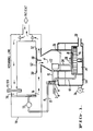
- Figure 1 shows a nebulizer of the present invention operably connected to a mechanical respirator 70.
- the nebulizer comprises, in a housing, compressed gas inlet 2, at one end of a compressed gas conduit 4, adapted to be connected to a compressed gas source.
- this compressed gas source is the same source which is furnishing oxygen-enriched air to the respirator, and provides compressed air or oxygen mixture to the nebulizer ranging up to about 345 kPA (50 psig).
- Compressed gas conduit 4 is connected at the other end to electrically operated nebulizer valve 6.
- electrically operated nebulizer valve 6 Examples of such valves which have been found useful include the Honeywell® Skinner® K4M ultraminiature 4-way solenoid operated pneumatic valve and Numatic® Mark 3 solenoid operated valves.
- Nebulizer valve 6 is connected by electrical lead wires 8, 8' to a signal source 72 on the respirator which controls the inhalation phase of the breathing cycle.
- signal sources include a respirator solenoid, such as a solenoid actuated inhalation valve, an external electronic monitoring system, or an electronic interface attached to a signal generator on respirator 70, such as an interface connected to a logic circuit in the respirator.
- the key criteria here is to select a signal source which is synchronized with the breathing cycle of the respirator.
- Nebulizer valve 6 also provides the conduits connecting the compressed gas source to turbine conduit 10 and to nebulizer conduit 12. Nebulizer valve 6 switches between two positions as electrical on/off signals are received. In the first position, during inhalation when the electric signal is "on”, a passageway is opened between compressed gas conduit 4 and nebulizer conduit 12, and turbine conduit 10 is sealed off. In the second position, during exhalation when the electric signal is "off”, a passageway is opened between compressed gas conduit 4 and turbine conduit 10, and nebulizer conduit 12 is sealed off. If desired, the effect of these signals could be reversed.
- Turbine conduit 10 terminates, at its other end, in one end of chamber 14 which houses a rotating turbine 16 on top of which is mounted magnet 18. At the other end of chamber 14 is an exhaust conduit 20.
- Nebulizer conduit 12 is attached, at its other end, to aerosol transducer 22, which includes liquid feed tube 24 extending into reservoir 26.
- Reservoir 26 includes magnetic stirring bar 28 which is located in the bottom of the reservoir.
- the liquid medicine contained in reservoir 26 is preferably kept at constant temperature by temperature bath 34. Alternatively, bath 34 may be changed or drained through spigot 36.
- the nebulizer is attached to respirator 70 at respirator input conduit 30 and at nebulizer output conduit 32.
- Compressed gas ranging up to about 345 kPA (50 psig), is provided continuously to the nebulizer unit through compressed gas inlet 2.
- This compressed gas may be premixed and enriched with oxygen.
- signal source 72 switches to the "on" position as the respirator exhalation port 74 closes and the respirator inhalation port 76 opens.
- This signal is simultaneously picked up by nebulizer valve 6, which is attached to signal source 72 by electrical leadwires 8, 8′, and switches nebulizer valve 6 to the first position, opening a passageway between compressed gas conduit 4 and nebulizer conduit 12.
- the flow of compressed gas through turbine conduit 10 into chamber 14 ceases, stopping the stirring action of magnetic stirring bar 28 in reservoir 26.
- Compressed gas flows through compressed gas conduit 4, nebulizer conduit 12 and into aerosol transducer 22 which converts liquid medicine in reservoir 26 into an aerosol having droplets with a mass median aerodynamic diameter less than about 5 micrometers.
- the aerosol is generated into the airspace above reservoir 26.
- compressed gas passes into the respirator and enters the nebulizer through respirator input 30.
- the compressed gas stream encounters wall 38 which deflects the air stream down into the airspace above reservoir 26, where it picks up the aerosol droplets and carries them through nebulizer output 32 and back into the mechanical respirator, and finally into the patient.
- FIG. 2 shows a cross-sectional view of a nebulizer of the present invention.
- Housing 40 can be constructed from plastic, metal or any other material suitable for holding a liquid temperature bath.
- Temperature bath 34 can be either cold or hot. Many methods are known for bringing such baths to and maintaining them at generally constant temperatures by those skilled in the art. For example, by using an ice water bath, the medicine in reservoir 26 can be maintained at 32 degree F (0 degrees C).
- a temperature bath 34 having a temperature greater than ambient air temperature can be obtained by applying sufficient heat to the exterior surface of housing 40 or by inserting a thermostatically controlled heating element through opening 44 in housing cover 42 to bring the liquid bath to and maintain it at the desired temperature.
- a means for draining temperature bath 34 is preferably provided. This can be accomplished in many ways. One such way is shown in Figure 2 where a rotatable spigot 36 is provided in the bottom of housing 40 such that when spigot 36 is in an open position, a passageway to the outside of housing 40 is opened, permitting an liquid in temperature bath 34 to drain, and such that when spigot 36 is in a closed position, the passageway to the outside of housing 40 is sealed off.
- Chamber 14 may be incorporated into a hollow recess in the bottom of housing 40.
- air turbine 16 can be rotatably mounted on plate 46 which is attached to the sides of the hollow recess as shown in Figure 2.
- Magnet 18 may be attached to the top of turbine 16, or may be molded into the top of turbine 16 as shown in Figure 2.
- plate 46 may have a single exhaust conduit 20, as shown in Figure 1 and 2, or may be perforated to permit the exhaust of the compressed gas stream from chamber 14.
- compressed gas is continuously supplied to nebulizer valve 6 through compressed gas inlet 2 and compressed gas conduit 4.
- Compressed gas conduit 4 ends at nebulizer valve 6, which contains a connector 7 for receiving electrical leadwires 8, 8′ from a respirator signal source.
- Nebulizer valve 6 switches between two positions as signals are received from the respirator signal source through leadwires 8, 8′. In the first position, nebulizer valve 6 opens a passageway between compressed gas conduit 4 and nebulizer conduit 12 and seals off turbine conduit 10. In the second position, nebulizer valve 6 opens a passageway between compressed gas conduit 4 and turbine conduit 10, sealing off nebulizer conduit 12.
- Turbine conduit 10 and nebulizer conduit 12 can be constructed of any material capable of channeling compressed gas. Preferably, however, they will be constructed from plastic tubing which is removably attached to permit easy cleaning and sterilization of the parts of the nebulizer unit after use, and to permit the removal of reservoir cover 48 to allow access to the interior of the reservoir. Many ways are known by those skilled in the art for providing such removable attachments. For example, a nipple, like that shown for the compressed gas inlet 2 in Figure 2, having an outside diameter slightly larger than the inside diameter of the plastic tubing used to form the conduits can be used.
- the wall of the plastic tubing is somewhat elastic, it can be forced over the end of such a nipple and will be frictionally held in position on the nipple until a sufficient force is exerted to pull it off the nipple.
- the force exerted by the compressed gas in the range used in this unit will not be sufficient to detach the tubing.
- a person pulling on the tubing can easily detach and reattach the tubing.
- Such a removable attachment can be used in any desired location.
- Reservoir 26 is contained within housing 40 in a separate, and preferably removable, container.
- Reservoir 26 can be constructed of any material suitable for holding and dispensing medicine, such as plastic, stainless steel or glass. Further the reservoir may be constructed to be sterilizable, and hence reusable, or constructed to be disposable after one use.
- the size of reservoir 26 is limited only by the size of the housing 40.
- reservoir 26 is of a size capable of holding at least 250 ml of liquid. This size permits up to 6 hours of operation before refilling or replacement of medication is necessary.
- the bottom of reservoir 26 may be sloped slightly to permit liquid feed tube 24 to drain essentially all of the liquid medication during use.
- Reservoir cover 48 is removably attached to the top of reservoir 26 to seal the reservoir off from the atmosphere during operation of the nebulizer unit, to allow access to reservoir 26, and to provide a means for attaching the nebulizer unit to the respirator.
- the respirator input 30, nebulizer output 32, and wall 38 can be conveniently provided in respirator adapter 52 which can be integral with or removably attached to reservoir cover 48.
- Aerosol transducer 22 with attached liquid feed tube 24 are preferably attached to reservoir cover 48.
- Magnetic stirring bar 28 may be of any size or material which will cooperate with the force exerted by magnet 18 to provide a stirring action when turbine 16 is rotated by compressed gas. Magnetic stirring bar 28 is preferably coated with an inert coating, such as Teflon, which permits easy sterilization and avoids any reaction with the liquid medicine.
- Figures 3 and 4 show a perspective exterior and sectional view of a nebulizer unit essentially as described above in Figure 2.
- Figure 3 shows spigot 36 in the closed position. In this position, the passageway from the inside of housing 40 to the outside through spigot 36 is closed and any liquid in temperature bath 34 cannot drain from housing 40.
- Figure 4 shows spigot 36 in the open position. In this position, the passageway from the inside of housing 40 to the outside through spigot 36 is open and any liquid in temperature bath 34 can drain from housing 40.
- the nebulizer unit is attached to an existing respirator by connecting respirator adapter 52 to the respirator hose carrying compressed air and/or oxygen mixture to the patient, and by tapping signal source on the respirator which is synchronized to the breathing cycle using electrical lead wires 8, 8′.
- the signal source is "off”
- nebulizer valve 6 switches to the second position and a passageway is opened allowing compressed gas to flow through turbine conduit 10. As discussed above, this rotates an air turbine mounted magnet in chamber 14, causing magnetic stirring bar 28 to spin, mixing the liquid in reservoir 26.
- This built-in mixing capability provides uniform nebulization of, for example, suspensions, colloids and liposomes in aqueous preparations over extended periods. While other mixing means are known and can be used, magnetic mixing as disclosed herein is preferred because the compressed gas can be used in conjunction with an air turbine, eliminating the need for an external power supply for the mixing function. Further, magnetic mixing is preferred because it thoroughly mixes without causing potential nebulization-destroying turbulence which may result when compressed gas is used directly to agitate the solution.
- nebulizer valve 6 switches to its first position, closing the passageway to turbine conduit 10 and opening the passageway to nebulizer conduit 12. This allows compressed gas to flow into aerosol transducer 22, nebulizing the liquid being drawn up through liquid feed tube 24 by Venturi vacuum, and filling the upper regions of reservoir cover 48 with the aerosol. As compressed gas passes into the nebulizer unit through respirator input 30, it is deflected downward by wall 38, picks up the aerosol and exits through nebulizer output 32, where it passes back into the respirator and is inhaled by the patient.
Landscapes
- Health & Medical Sciences (AREA)
- Engineering & Computer Science (AREA)
- General Health & Medical Sciences (AREA)
- Public Health (AREA)
- Anesthesiology (AREA)
- Biomedical Technology (AREA)
- Heart & Thoracic Surgery (AREA)
- Hematology (AREA)
- Life Sciences & Earth Sciences (AREA)
- Animal Behavior & Ethology (AREA)
- Veterinary Medicine (AREA)
- Pulmonology (AREA)
- Bioinformatics & Cheminformatics (AREA)
- Emergency Medicine (AREA)
- Nozzles (AREA)
- Respiratory Apparatuses And Protective Means (AREA)
- Lubrication Of Internal Combustion Engines (AREA)
- Acyclic And Carbocyclic Compounds In Medicinal Compositions (AREA)
- Measuring Pulse, Heart Rate, Blood Pressure Or Blood Flow (AREA)
- Electrophonic Musical Instruments (AREA)
- Ultra Sonic Daignosis Equipment (AREA)
- Control Of Motors That Do Not Use Commutators (AREA)
Priority Applications (1)
| Application Number | Priority Date | Filing Date | Title |
|---|---|---|---|
| AT88110538T ATE81296T1 (de) | 1987-07-08 | 1988-07-01 | Durch signal intermittierend betaetigter vernebler. |
Applications Claiming Priority (2)
| Application Number | Priority Date | Filing Date | Title |
|---|---|---|---|
| US07/071,202 US4832012A (en) | 1987-07-08 | 1987-07-08 | Intermittent signal actuated nebulizer |
| US71202 | 1987-07-08 |
Publications (3)
| Publication Number | Publication Date |
|---|---|
| EP0298389A2 EP0298389A2 (en) | 1989-01-11 |
| EP0298389A3 EP0298389A3 (en) | 1989-09-27 |
| EP0298389B1 true EP0298389B1 (en) | 1992-10-07 |
Family
ID=22099897
Family Applications (1)
| Application Number | Title | Priority Date | Filing Date |
|---|---|---|---|
| EP88110538A Expired - Lifetime EP0298389B1 (en) | 1987-07-08 | 1988-07-01 | Intermittent signal actuated nebulizer |
Country Status (7)
| Country | Link |
|---|---|
| US (1) | US4832012A (ja) |
| EP (1) | EP0298389B1 (ja) |
| JP (1) | JPS6480372A (ja) |
| AT (1) | ATE81296T1 (ja) |
| AU (1) | AU600877B2 (ja) |
| CA (1) | CA1291683C (ja) |
| DE (1) | DE3875169T2 (ja) |
Families Citing this family (54)
| Publication number | Priority date | Publication date | Assignee | Title |
|---|---|---|---|---|
| US5322057A (en) * | 1987-07-08 | 1994-06-21 | Vortran Medical Technology, Inc. | Intermittent signal actuated nebulizer synchronized to operate in the exhalation phase, and its method of use |
| US4951659A (en) * | 1988-11-04 | 1990-08-28 | Automatic Liquid Packaging, Inc. | Nebulizer with cooperating disengageable on-line heater |
| US5280784A (en) * | 1990-09-19 | 1994-01-25 | Paul Ritzau Pari-Werk Gmbh | Device in particular and inhalating device for treating the lung and the respiratory tracts |
| US5404871A (en) * | 1991-03-05 | 1995-04-11 | Aradigm | Delivery of aerosol medications for inspiration |
| AU6130394A (en) * | 1991-03-05 | 1994-08-15 | Miris Medical Corporation | Apparatus for providing a timed release of an amount of aerosol medication |
| US5469750A (en) * | 1991-03-05 | 1995-11-28 | Aradigm Corporation | Method and apparatus for sensing flow in two directions and automatic calibration thereof |
| US5392768A (en) * | 1991-03-05 | 1995-02-28 | Aradigm | Method and apparatus for releasing a controlled amount of aerosol medication over a selectable time interval |
| US5450336A (en) * | 1991-03-05 | 1995-09-12 | Aradigm Corporation | Method for correcting the drift offset of a transducer |
| US5277175A (en) * | 1991-07-12 | 1994-01-11 | Riggs John H | Continuous flow nebulizer apparatus and method, having means maintaining a constant-level reservoir |
| WO1993001826A1 (en) * | 1991-07-19 | 1993-02-04 | East Carolina University | Method of treating asthma |
| GB9120013D0 (en) * | 1991-09-19 | 1991-11-06 | Wellcome Found | Method and apparatus for administering respirable pharmaceutical particles |
| GB9120005D0 (en) * | 1991-09-19 | 1991-11-06 | Wellcome Found | Method of administering phospholipid dispersions |
| JP3088168B2 (ja) * | 1991-12-13 | 2000-09-18 | ティーディーケイ株式会社 | 光記録媒体およびその製造方法 |
| US5355872B1 (en) * | 1992-03-04 | 1998-10-20 | John H Riggs | Low flow rate nebulizer apparatus and method of nebulization |
| US5287847A (en) * | 1992-07-24 | 1994-02-22 | Vortran Medical Technology, Inc. | Universal nebulizer |
| EP0590289A1 (en) * | 1992-09-28 | 1994-04-06 | Engström Medical Ab | Patient connector |
| US5388574A (en) * | 1993-07-29 | 1995-02-14 | Ingebrethsen; Bradley J. | Aerosol delivery article |
| US5570682A (en) * | 1993-12-14 | 1996-11-05 | Ethex International, Inc. | Passive inspiratory nebulizer system |
| US5479920A (en) * | 1994-03-01 | 1996-01-02 | Vortran Medical Technology, Inc. | Breath actuated medicinal aerosol delivery apparatus |
| IL114154A0 (en) | 1994-06-17 | 1995-10-31 | Trudell Medical Ltd | Nebulizing catheter system and methods of use and manufacture |
| US6729334B1 (en) | 1994-06-17 | 2004-05-04 | Trudell Medical Limited | Nebulizing catheter system and methods of use and manufacture |
| US5642730A (en) * | 1994-06-17 | 1997-07-01 | Trudell Medical Limited | Catheter system for delivery of aerosolized medicine for use with pressurized propellant canister |
| US5522385A (en) * | 1994-09-27 | 1996-06-04 | Aradigm Corporation | Dynamic particle size control for aerosolized drug delivery |
| US5564415A (en) * | 1995-06-07 | 1996-10-15 | Lifecare International, Inc. | Humidifier for a ventilator |
| US6105929A (en) * | 1997-11-14 | 2000-08-22 | Salter Labs | Control valve for gas supply to a nebulizer |
| CA2322193C (en) | 1998-03-05 | 2006-10-24 | Batelle Memorial Institute | Pulmonary dosing system and method |
| GB2343122B (en) * | 1998-10-26 | 2003-01-08 | Medic Aid Ltd | Improvements in and relating to nebulisers |
| US6584971B1 (en) | 1999-01-04 | 2003-07-01 | Medic-Aid Limited | Drug delivery apparatus |
| GB0003197D0 (en) | 2000-02-11 | 2000-04-05 | Aid Medic Ltd | Improvements in and relating to controlling drug delivery |
| NZ532220A (en) * | 2001-09-12 | 2006-02-24 | Norton Healthcare Ltd | Breath-enhanced ultrasonic nebulizer and dedicated unit dose ampoule |
| EP1515768B1 (en) * | 2002-05-07 | 2013-11-06 | The State University of New York at Stony Brook | Devices for targeted endobronchial therapy |
| US7267120B2 (en) * | 2002-08-19 | 2007-09-11 | Allegiance Corporation | Small volume nebulizer |
| CA2771129C (en) * | 2003-10-31 | 2015-09-29 | Trudell Medical International | System and method for manipulating a catheter for delivering a substance to a body cavity |
| US20060073173A1 (en) * | 2004-10-04 | 2006-04-06 | Maria Banach | Large-scale manufacturing process for the production of pharmaceutical compositions |
| CN101454041B (zh) * | 2005-09-20 | 2012-12-12 | 呼吸科技公司 | 对患者进行呼吸支持的系统、方法和装置 |
| USD640784S1 (en) | 2007-10-05 | 2011-06-28 | Vapotherm, Inc. | Hyperthermic humidification system |
| US8905023B2 (en) * | 2007-10-05 | 2014-12-09 | Vapotherm, Inc. | Hyperthermic humidification system |
| WO2010091259A2 (en) * | 2009-02-06 | 2010-08-12 | Vapotherm, Inc. | Heated nebulizer devices, nebulizer systems, and methods for inhalation therapy |
| JP2012522798A (ja) | 2009-04-01 | 2012-09-27 | プロメディオール, インコーポレイテッド | 血清アミロイドpの肺および鼻への送達 |
| US10857311B2 (en) | 2010-01-12 | 2020-12-08 | Omega Life Science Ltd. | Method and apparatus for producing fine concentrated aerosol |
| US8915245B2 (en) | 2010-10-07 | 2014-12-23 | Vapotherm, Inc. | Nebulizer systems, apparatus and methods for respiratory therapy |
| US20120192862A1 (en) * | 2011-01-31 | 2012-08-02 | Carefusion 303, Inc. | Patient-controlled aerosol administration |
| EP3216475B1 (en) | 2012-01-24 | 2020-07-22 | Vapotherm, Inc. | Systems for providing respiratory therapy |
| GB2500588B (en) * | 2012-03-24 | 2017-02-01 | Rhinocare Ltd | Systems and methods of hyperthermal treatment |
| EP3488889A1 (en) | 2013-08-08 | 2019-05-29 | Vapotherm, Inc. | Respiratory therapy condensation adaptor |
| EP3412327A1 (en) | 2014-06-06 | 2018-12-12 | Vapotherm, Inc. | Heated nebulizer adapter for respiratory therapy |
| ES2806976T3 (es) | 2014-10-13 | 2021-02-19 | Omega Life Science Ltd | Nebulizadores |
| CN112368040A (zh) | 2018-05-31 | 2021-02-12 | 蒸汽热能公司 | 近机器侧雾化器 |
| US12102755B2 (en) | 2018-05-31 | 2024-10-01 | Vapotherm, Inc. | Cannula-based vibrating mesh nebulizer |
| CN109876250B (zh) * | 2019-04-01 | 2023-11-24 | 威海盛洁医疗科技有限公司 | 一种智能感应控制可调节喷雾的网式雾化器及其使用方法 |
| WO2020225817A1 (en) * | 2019-05-08 | 2020-11-12 | Respinova Ltd. | A system for delivering inhaled therapies |
| KR102240854B1 (ko) * | 2019-07-31 | 2021-04-14 | 국방과학연구소 | 휴대용 생물입자발생장치 |
| US11878115B2 (en) | 2019-09-26 | 2024-01-23 | Vapotherm, Inc. | Internal cannula mounted nebulizer |
| CN114632234B (zh) * | 2022-04-12 | 2024-02-13 | 泰州市人民医院 | 一种雾化吸入装置 |
Family Cites Families (20)
| Publication number | Priority date | Publication date | Assignee | Title |
|---|---|---|---|---|
| US2466468A (en) * | 1946-12-23 | 1949-04-05 | Neal Harry Herbert | Magnetic mixer |
| US2774346A (en) * | 1953-07-13 | 1956-12-18 | Dorothy L Bischof | Respirator |
| US3211433A (en) * | 1963-12-02 | 1965-10-12 | Joseph E Chrostowski | Magnetic stirring apparatus |
| US3362404A (en) * | 1964-11-16 | 1968-01-09 | Bennett Respiration Products I | Respiration apparatus for administering intermittent positive pressure breathing therapy |
| US3345047A (en) * | 1966-02-07 | 1967-10-03 | Alan L Gooden | Apparatus and method for administering humidified anesthetic gases |
| US3610237A (en) * | 1968-10-07 | 1971-10-05 | Michigan Instr Inc | Inhalation positive pressure breathing apparatus |
| US4393013A (en) * | 1970-05-20 | 1983-07-12 | J. C. Schumacher Company | Vapor mass flow control system |
| US3662751A (en) * | 1970-05-20 | 1972-05-16 | Michigan Instr Inc | Automatic respirator-inhalation therapy device |
| US3744764A (en) * | 1971-02-02 | 1973-07-10 | Coca Cola Co | Agitating apparatus |
| US3724454A (en) * | 1971-02-04 | 1973-04-03 | Bendix Corp | Humidifier - nebulizer |
| BE791154A (fr) * | 1971-11-10 | 1973-05-09 | Synthelabo | Respirateur a turbine |
| US3990442A (en) * | 1975-06-06 | 1976-11-09 | Patneau Robert A | Respiratory treatment device |
| US4106503A (en) * | 1977-03-11 | 1978-08-15 | Richard R. Rosenthal | Metering system for stimulating bronchial spasm |
| US4279250A (en) * | 1977-11-10 | 1981-07-21 | Airco, Inc. | Drug nebulizing system for medical ventilators of the volume-limited type |
| DE3008406A1 (de) * | 1978-12-04 | 1981-02-05 | Medizin Labortechnik Veb K | Beatmungsgeraet mit vernebelungsvorrichtung |
| FI66753C (fi) * | 1979-01-05 | 1984-12-10 | Taisto Haekkinen | Rytmiseringsventil foer andningen avsedd foer respirator ellerfoer annan upplivningsanvaendning laempad anordning |
| US4471773A (en) * | 1981-11-19 | 1984-09-18 | Bunnell Life System, Inc. | Apparatus and method for delivering medication to patient's respiratory system |
| DE3224849A1 (de) * | 1982-07-02 | 1984-01-05 | Plantorgan Werk Heinrich G.E. Christensen, KG, 2903 Bad Zwischenahn | Dampfinhaliergeraet |
| FI67178C (fi) * | 1983-01-07 | 1985-02-11 | Etelae Haemeen Keuhkovammayhdi | Respirator som aer avsedd foer lungsjuka illamaoende eller medvetsloesa maenskor och dess anvaendning som en sprayanordning |
| GB2148127B (en) * | 1983-08-25 | 1986-07-30 | Penlon Ltd | Gas humidifying apparatus and method |
-
1987
- 1987-07-08 US US07/071,202 patent/US4832012A/en not_active Expired - Fee Related
-
1988
- 1988-07-01 EP EP88110538A patent/EP0298389B1/en not_active Expired - Lifetime
- 1988-07-01 DE DE8888110538T patent/DE3875169T2/de not_active Expired - Fee Related
- 1988-07-01 AT AT88110538T patent/ATE81296T1/de active
- 1988-07-04 CA CA000571043A patent/CA1291683C/en not_active Expired - Lifetime
- 1988-07-06 AU AU18741/88A patent/AU600877B2/en not_active Ceased
- 1988-07-07 JP JP63170008A patent/JPS6480372A/ja active Pending
Also Published As
| Publication number | Publication date |
|---|---|
| AU1874188A (en) | 1989-01-12 |
| DE3875169T2 (de) | 1993-02-25 |
| JPS6480372A (en) | 1989-03-27 |
| EP0298389A3 (en) | 1989-09-27 |
| US4832012A (en) | 1989-05-23 |
| AU600877B2 (en) | 1990-08-23 |
| DE3875169D1 (de) | 1992-11-12 |
| ATE81296T1 (de) | 1992-10-15 |
| EP0298389A2 (en) | 1989-01-11 |
| CA1291683C (en) | 1991-11-05 |
Similar Documents
| Publication | Publication Date | Title |
|---|---|---|
| EP0298389B1 (en) | Intermittent signal actuated nebulizer | |
| US5080093A (en) | Intermittant signal actuated nebulizer | |
| US6805118B2 (en) | Pulmonary dosing system and method | |
| US5322057A (en) | Intermittent signal actuated nebulizer synchronized to operate in the exhalation phase, and its method of use | |
| US6705316B2 (en) | Pulmonary dosing system and method | |
| US4805609A (en) | Pressurized ventilation system for patients | |
| EP3254632B1 (en) | Humidification in breathing circuits | |
| US5388571A (en) | Positive-pressure ventilator system with controlled access for nebulizer component servicing | |
| EP0156409A2 (en) | Device for moistening parts of the human body | |
| US20090241948A1 (en) | Humidification in breathing circuits | |
| JPH06507814A (ja) | 連続フロー式ネブライザ装置及び方法 | |
| US20120192863A1 (en) | Humidification in breathing circuits | |
| JP4469972B2 (ja) | 呼吸器系への薬剤の送給のための装置及び方法 | |
| CN110812627B (zh) | 一种便携式雾化治疗仪 | |
| JP2001054574A (ja) | 医用ネブライザ | |
| US5918593A (en) | Ultrasonic atomizer for respiration systems | |
| CN209848091U (zh) | 同步雾化高流量呼吸湿化治疗仪 | |
| CN217339639U (zh) | 一种自动调节雾化量的雾化器 | |
| CN213048868U (zh) | 一种麻醉剂雾化装置 | |
| CN210872226U (zh) | 一种实验猴用雾化给药面罩 | |
| CN218458425U (zh) | 一种用于中药雾化吸入的简易便携式雾化器 | |
| CN216496899U (zh) | 一种雾化器 | |
| CN114209936A (zh) | 一种儿科用智能式咽喉雾化器 | |
| CN113952562A (zh) | 一种雾化器 | |
| CN217286782U (zh) | 压缩式雾化机 |
Legal Events
| Date | Code | Title | Description |
|---|---|---|---|
| PUAI | Public reference made under article 153(3) epc to a published international application that has entered the european phase |
Free format text: ORIGINAL CODE: 0009012 |
|
| AK | Designated contracting states |
Kind code of ref document: A2 Designated state(s): AT BE CH DE ES FR GB GR IT LI LU NL SE |
|
| PUAL | Search report despatched |
Free format text: ORIGINAL CODE: 0009013 |
|
| AK | Designated contracting states |
Kind code of ref document: A3 Designated state(s): AT BE CH DE ES FR GB GR IT LI LU NL SE |
|
| 17P | Request for examination filed |
Effective date: 19891130 |
|
| 17Q | First examination report despatched |
Effective date: 19910219 |
|
| RIN1 | Information on inventor provided before grant (corrected) |
Inventor name: LEE, JAMES I.C. Inventor name: RAABE, OTTO G. |
|
| RAP1 | Party data changed (applicant data changed or rights of an application transferred) |
Owner name: VORTRAN MEDICAL TECHNOLOGY, INC. |
|
| GRAA | (expected) grant |
Free format text: ORIGINAL CODE: 0009210 |
|
| AK | Designated contracting states |
Kind code of ref document: B1 Designated state(s): AT BE CH DE ES FR GB GR IT LI LU NL SE |
|
| PG25 | Lapsed in a contracting state [announced via postgrant information from national office to epo] |
Ref country code: IT Free format text: LAPSE BECAUSE OF FAILURE TO SUBMIT A TRANSLATION OF THE DESCRIPTION OR TO PAY THE FEE WITHIN THE PRE;WARNING: LAPSES OF ITALIAN PATENTS WITH EFFECTIVE DATE BEFORE 2007 MAY HAVE OCCURRED AT ANY TIME BEFORE 2007. THE CORRECT EFFECTIVE DATE MAY BE DIFFERENT FROM THE ONE RECORDED.SCRIBED TIME-LIMIT Effective date: 19921007 Ref country code: SE Effective date: 19921007 Ref country code: ES Free format text: THE PATENT HAS BEEN ANNULLED BY A DECISION OF A NATIONAL AUTHORITY Effective date: 19921007 Ref country code: AT Effective date: 19921007 Ref country code: BE Effective date: 19921007 Ref country code: FR Effective date: 19921007 Ref country code: NL Effective date: 19921007 Ref country code: GR Free format text: LAPSE BECAUSE OF FAILURE TO SUBMIT A TRANSLATION OF THE DESCRIPTION OR TO PAY THE FEE WITHIN THE PRESCRIBED TIME-LIMIT Effective date: 19921007 |
|
| REF | Corresponds to: |
Ref document number: 81296 Country of ref document: AT Date of ref document: 19921015 Kind code of ref document: T |
|
| REF | Corresponds to: |
Ref document number: 3875169 Country of ref document: DE Date of ref document: 19921112 |
|
| EN | Fr: translation not filed | ||
| NLV1 | Nl: lapsed or annulled due to failure to fulfill the requirements of art. 29p and 29m of the patents act | ||
| PGFP | Annual fee paid to national office [announced via postgrant information from national office to epo] |
Ref country code: GB Payment date: 19930618 Year of fee payment: 6 |
|
| PGFP | Annual fee paid to national office [announced via postgrant information from national office to epo] |
Ref country code: CH Payment date: 19930714 Year of fee payment: 6 |
|
| PGFP | Annual fee paid to national office [announced via postgrant information from national office to epo] |
Ref country code: DE Payment date: 19930719 Year of fee payment: 6 |
|
| PG25 | Lapsed in a contracting state [announced via postgrant information from national office to epo] |
Ref country code: LU Free format text: LAPSE BECAUSE OF NON-PAYMENT OF DUE FEES Effective date: 19930731 |
|
| PLBE | No opposition filed within time limit |
Free format text: ORIGINAL CODE: 0009261 |
|
| STAA | Information on the status of an ep patent application or granted ep patent |
Free format text: STATUS: NO OPPOSITION FILED WITHIN TIME LIMIT |
|
| 26N | No opposition filed | ||
| PG25 | Lapsed in a contracting state [announced via postgrant information from national office to epo] |
Ref country code: GB Effective date: 19940701 |
|
| PG25 | Lapsed in a contracting state [announced via postgrant information from national office to epo] |
Ref country code: LI Effective date: 19940731 Ref country code: CH Effective date: 19940731 |
|
| GBPC | Gb: european patent ceased through non-payment of renewal fee |
Effective date: 19940701 |
|
| REG | Reference to a national code |
Ref country code: CH Ref legal event code: PL |
|
| PG25 | Lapsed in a contracting state [announced via postgrant information from national office to epo] |
Ref country code: DE Effective date: 19950401 |