EP0296773B1 - Method of operating a system for burning pulverised fuel - Google Patents
Method of operating a system for burning pulverised fuel Download PDFInfo
- Publication number
- EP0296773B1 EP0296773B1 EP88305589A EP88305589A EP0296773B1 EP 0296773 B1 EP0296773 B1 EP 0296773B1 EP 88305589 A EP88305589 A EP 88305589A EP 88305589 A EP88305589 A EP 88305589A EP 0296773 B1 EP0296773 B1 EP 0296773B1
- Authority
- EP
- European Patent Office
- Prior art keywords
- pulverised
- fuel
- oxy
- burner
- fuel burner
- Prior art date
- Legal status (The legal status is an assumption and is not a legal conclusion. Google has not performed a legal analysis and makes no representation as to the accuracy of the status listed.)
- Expired - Lifetime
Links
Images


Classifications
-
- F—MECHANICAL ENGINEERING; LIGHTING; HEATING; WEAPONS; BLASTING
- F23—COMBUSTION APPARATUS; COMBUSTION PROCESSES
- F23K—FEEDING FUEL TO COMBUSTION APPARATUS
- F23K3/00—Feeding or distributing of lump or pulverulent fuel to combustion apparatus
- F23K3/02—Pneumatic feeding arrangements, i.e. by air blast
-
- Y—GENERAL TAGGING OF NEW TECHNOLOGICAL DEVELOPMENTS; GENERAL TAGGING OF CROSS-SECTIONAL TECHNOLOGIES SPANNING OVER SEVERAL SECTIONS OF THE IPC; TECHNICAL SUBJECTS COVERED BY FORMER USPC CROSS-REFERENCE ART COLLECTIONS [XRACs] AND DIGESTS
- Y02—TECHNOLOGIES OR APPLICATIONS FOR MITIGATION OR ADAPTATION AGAINST CLIMATE CHANGE
- Y02E—REDUCTION OF GREENHOUSE GAS [GHG] EMISSIONS, RELATED TO ENERGY GENERATION, TRANSMISSION OR DISTRIBUTION
- Y02E20/00—Combustion technologies with mitigation potential
- Y02E20/34—Indirect CO2mitigation, i.e. by acting on non CO2directly related matters of the process, e.g. pre-heating or heat recovery
Definitions
- This invention relates to a method of operating a system for burning pulverised fuel and, more particularly but not exclusively, is concerned with a method of operating a system for burning pulverised coal.
- GB-A-2146758 discloses a method of operating a system for burning pulverised fuel, which system comprises an oxy-fuel burner, means for delivering oxygen to said oxy-fuel burner, and a dense phase material flow transport system for delivering pulverised material to said oxy-fuel burner.
- the ratio (by weight) of pulverised material to propellant is between 0.5: 1 to 10: 1.
- the use of supplementary fuel gas and oxygen or oxygen enriched air is advocated at higher ratios within this range.
- This system has the same disadvantages as those described above.
- the present invention at least in its preferred embodiments, aims to provide more efficient combustion.
- the present invention is characterized in that said dense phase material flow transport system is delivering between 20 and 30 kg of pulverised material to the oxy-fuel burner per 1 kg of propellant whereby substantially complete combustion takes place without the necessity of adding fuel gas to the burner.
- the propellant for example air or nitrogen, will typically be at 2-2.5 bar A.
- the pulverised fuel will be between 100 and 200 mesh (150-75 ⁇ m).
- pulverised material Preferably, 60% to 80%, advantageously 70 to 75%, and more advantageously 75% by volume of said pulverised material will pass through a 75 ⁇ m filter.
- passageways may be provided in the oxy-fuel burner to convey natural gas to the outlet of the burner during start-up of a furnace.
- pulverised coal (70% by volume of which will pass though a 75 ⁇ m filter) is stored in a fully enclosed silo 1.
- the pulverised coal is introduced into a coal injector 2 via an upper dome valve 3 and a lower dome valve 4.
- a motor 5 drives a mechanism which introduces the pulverised coal into a feed pipe 6 at a rate of 1000 kg/h.
- the pulverised coal is conveyed along the feed pipe 6 by air which is introduced through pipe 7 at a rate of 35 kg/h and at a pressure of about 2.3 bar A.
- the pulverised coal is introduced into the central tube of an oxy-fuel burner 10.
- Oxygen is supplied to the oxy-fuel burner 10 through pipe 11 and mixes with the pulverised coal at the outlet 12 of the oxy-fuel burner 10.
- the oxy-fuel burner 10 comprises a central tube 13 which is made of stainless steel and extends from the inlet 14 to the outlet 15 of the oxy-fuel burner 10.
- the central tube 13 extends through a tube 16 which itself extends through a tube 17.
- the tube 17 defines the radial inner wall of an annular oxygen supply passageway 18 which extends from a radial wall 19 to the outlet 15 of the oxy-fuel burner 10.
- Twelve natural gas pipes 20 are disposed in the oxygen-supply passageway 18 and extend from a header 21 to the outlet 15 as shown.
- pulverised coal from feed pipe 6 passes through the central tube 13 to the outlet 15 of the oxy-fuel burner 10.
- Oxygen from pipe 11 enters the burner 10 through oxygen inlet 22 and passes through the oxygen supply passageway 18 to the outlet 15 where substantially complete combustion takes place.
- the tip of the burner 10 is cooled by water which enters the burner 10 through water inlet 23, flows through passageways 24 and 25 and leaves through water outlet 26.
- natural gas can be admitted to the burner 10 via pipe 27, and natural gas inlet 28.
- the natural gas passes into the header 21 and thence passes to the outlet 15 via the natural gas pipes 20.
- the natural gas is used during start-up.
Landscapes
- Engineering & Computer Science (AREA)
- Chemical & Material Sciences (AREA)
- Combustion & Propulsion (AREA)
- Mechanical Engineering (AREA)
- General Engineering & Computer Science (AREA)
- Processing Of Solid Wastes (AREA)
- Air Supply (AREA)
Description
- This invention relates to a method of operating a system for burning pulverised fuel and, more particularly but not exclusively, is concerned with a method of operating a system for burning pulverised coal.
- It has been proposed to burn pulverised fuel in an oxy-fuel burner. However, even with the use of pure oxygen it is difficult to obtain satisfactory combustion with certain fuels. In such cases the flame tends to be a relatively low temperature luminant flame and the ash may contain an appreciable quantity of uncombusted carbon.
- GB-A-2146758 discloses a method of operating a system for burning pulverised fuel, which system comprises an oxy-fuel burner, means for delivering oxygen to said oxy-fuel burner, and a dense phase material flow transport system for delivering pulverised material to said oxy-fuel burner.
- In this method the ratio (by weight) of pulverised material to propellant is between 0.5: 1 to 10: 1. The use of supplementary fuel gas and oxygen or oxygen enriched air is advocated at higher ratios within this range. This system has the same disadvantages as those described above.
- The present invention, at least in its preferred embodiments, aims to provide more efficient combustion.
- The present invention is characterized in that said dense phase material flow transport system is delivering between 20 and 30 kg of pulverised material to the oxy-fuel burner per 1 kg of propellant whereby substantially complete combustion takes place without the necessity of adding fuel gas to the burner.
- The propellant, for example air or nitrogen, will typically be at 2-2.5 bar A.
- Advantageously, the pulverised fuel will be between 100 and 200 mesh (150-75 µm).
- Preferably, 60% to 80%, advantageously 70 to 75%, and more advantageously 75% by volume of said pulverised material will pass through a 75 µm filter.
- Heretofore, it has been essential for oxy-fuel burners for burning pulverised fuel to incorporate swirlers either for the pulverised fuel or the oxygen. When using a dense phase material flow transport system this may be unnecessary. Furthermore, it has been found possible to obtain satisfactory combustion of pulverised materials hitherto regarded as having too low a carbon content for economic combustion. This is a most significant advantage since it enables materials which would hitherto have been discarded as waste to be used as a viable energy source. Furthermore, disposal of the fly ash produced by such materials will normally be far less expensive than disposal of the unburnt material.
- If desired, passageways may be provided in the oxy-fuel burner to convey natural gas to the outlet of the burner during start-up of a furnace.
- For a better understanding of the present invention reference will now be made, by way of example, to the accompanying drawings, in which:
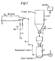
- Figure 1 is a simplified flow sheet of a system for burning pulverised fuel in accordance with the invention;
- Figures 2A and 2B together show a plan view, partly in cross-section, of an experimental oxygen/natural gas/pulverised fuel burner used in the system; and
- Figure 3 is an end view looking in the direction of line III-III in Figure 2.
- Referring to Figure 1 of the drawings 30t of pulverised coal (70% by volume of which will pass though a 75 µm filter) is stored in a fully enclosed silo 1. The pulverised coal is introduced into a coal injector 2 via an upper dome valve 3 and a lower dome valve 4. A
motor 5 drives a mechanism which introduces the pulverised coal into a feed pipe 6 at a rate of 1000 kg/h. The pulverised coal is conveyed along the feed pipe 6 by air which is introduced through pipe 7 at a rate of 35 kg/h and at a pressure of about 2.3 bar A. - The equipment thus far described is known as a "dense phase material flow transport system" and can be obtained from Simon-Macawber Limited of England.
- The pulverised coal is introduced into the central tube of an oxy-
fuel burner 10. Oxygen is supplied to the oxy-fuel burner 10 throughpipe 11 and mixes with the pulverised coal at theoutlet 12 of the oxy-fuel burner 10. - In tests the pulverised fuel and oxygen burnt with an intense high temperature flame. This was quite remarkable bearing in mind that the same pulverised coal had burnt with a low temperature luminant flare in a conventional oxy-fuel burner system. The ash had the appearance of silica sand and negligible residual carbon was found.
- Referring now to Figures 2 and 3, the oxy-
fuel burner 10 comprises acentral tube 13 which is made of stainless steel and extends from theinlet 14 to theoutlet 15 of the oxy-fuel burner 10. Thecentral tube 13 extends through atube 16 which itself extends through atube 17. Thetube 17 defines the radial inner wall of an annularoxygen supply passageway 18 which extends from aradial wall 19 to theoutlet 15 of the oxy-fuel burner 10. Twelvenatural gas pipes 20 are disposed in the oxygen-supply passageway 18 and extend from aheader 21 to theoutlet 15 as shown. - In use, pulverised coal from feed pipe 6 passes through the
central tube 13 to theoutlet 15 of the oxy-fuel burner 10. Oxygen frompipe 11 enters theburner 10 throughoxygen inlet 22 and passes through theoxygen supply passageway 18 to theoutlet 15 where substantially complete combustion takes place. - The tip of the
burner 10 is cooled by water which enters theburner 10 throughwater inlet 23, flows throughpassageways water outlet 26. - If desired, natural gas can be admitted to the
burner 10 viapipe 27, andnatural gas inlet 28. The natural gas passes into theheader 21 and thence passes to theoutlet 15 via thenatural gas pipes 20. The natural gas is used during start-up.
Claims (5)
Applications Claiming Priority (2)
| Application Number | Priority Date | Filing Date | Title |
|---|---|---|---|
| GB8715031 | 1987-06-26 | ||
| GB08715031A GB2206196A (en) | 1987-06-26 | 1987-06-26 | System for burning pulverised fuel |
Publications (3)
| Publication Number | Publication Date |
|---|---|
| EP0296773A2 EP0296773A2 (en) | 1988-12-28 |
| EP0296773A3 EP0296773A3 (en) | 1989-03-22 |
| EP0296773B1 true EP0296773B1 (en) | 1992-01-08 |
Family
ID=10619626
Family Applications (1)
| Application Number | Title | Priority Date | Filing Date |
|---|---|---|---|
| EP88305589A Expired - Lifetime EP0296773B1 (en) | 1987-06-26 | 1988-06-20 | Method of operating a system for burning pulverised fuel |
Country Status (11)
| Country | Link |
|---|---|
| US (1) | US4864943A (en) |
| EP (1) | EP0296773B1 (en) |
| JP (1) | JPS6419210A (en) |
| KR (1) | KR890000835A (en) |
| CN (1) | CN1030288A (en) |
| BR (1) | BR8803019A (en) |
| CA (1) | CA1305366C (en) |
| DE (1) | DE3867543D1 (en) |
| ES (1) | ES2029020T3 (en) |
| GB (1) | GB2206196A (en) |
| ZA (1) | ZA884380B (en) |
Families Citing this family (5)
| Publication number | Priority date | Publication date | Assignee | Title |
|---|---|---|---|---|
| US5593301A (en) * | 1993-07-09 | 1997-01-14 | Alliant Techsystems, Inc. | Apparatus and method for burning energetic material |
| CN101280917B (en) * | 2008-05-13 | 2010-04-14 | 吕伟鹏 | Gas, coal powder, oxygen-enriched mixed combustion device |
| CN103104930B (en) * | 2013-03-06 | 2015-12-16 | 湖南高翔重工科技有限公司 | A kind of high order breeze atomizing device |
| JP6504370B2 (en) * | 2016-07-26 | 2019-04-24 | Jfeスチール株式会社 | Method of producing molten iron by electric furnace |
| CN109084303A (en) * | 2018-08-14 | 2018-12-25 | 中冶南方武汉钢铁设计研究院有限公司 | Limekiln gas-solid double fuel multifuel combustion method and device |
Family Cites Families (18)
| Publication number | Priority date | Publication date | Assignee | Title |
|---|---|---|---|---|
| DE2538785C3 (en) * | 1975-09-01 | 1978-09-14 | 2000 Hamburg | Device for saving compressed gas when injecting solids with the aid of pressure vessel conveyors |
| DE2806363C2 (en) * | 1977-02-18 | 1985-06-27 | Combustion Engineering, Inc., Windsor, Conn. | Method of igniting the combustion of coal dust |
| US4221174A (en) * | 1978-05-16 | 1980-09-09 | Combustion Engineering, Inc. | Direct ignition of a fluctuating fuel stream |
| US4263856A (en) * | 1979-02-08 | 1981-04-28 | Combustion Engineering, Inc. | Providing supplemental pulverized coal for load regain |
| DE7904137U1 (en) * | 1979-02-15 | 1982-09-30 | Pillard Feuerungen GmbH, 6204 Taunusstein | BURNER FOR POWDER-SHAPED OR FINE-GRAINED SOLID FUELS AND COMBINATIONS OF SOLID, LIQUID AND / OR GASEOUS FUELS FOR THE MOST POSSIBLE ADJUSTMENT OF THE FLAME SHAPE, DURING OPERATION |
| US4228747A (en) * | 1979-02-22 | 1980-10-21 | Combustion Engineering, Inc. | High energy arc ignition of pulverized coal |
| US4241673A (en) * | 1979-11-05 | 1980-12-30 | Combustion Engineering, Inc. | Direct ignition of pulverized coal |
| GB2096085B (en) * | 1981-04-01 | 1985-06-12 | Carves Simon Ltd | A system for transporting coal for charging into coking ovens |
| JPS5816106A (en) * | 1981-05-30 | 1983-01-29 | Kobe Steel Ltd | Method of mixed-fuel burning to decrease nox for pulverized coal |
| CA1218903A (en) * | 1982-10-19 | 1987-03-10 | Ian Poll | Process and burner for the partial combustion of solid fuel |
| US4664042A (en) * | 1983-01-24 | 1987-05-12 | Combustion Engineering, Inc. | Method of decreasing ash fouling |
| GB2141815B (en) * | 1983-06-16 | 1986-07-30 | Boc Group Plc | Method and apparatus for burning fuel |
| JPS60204A (en) * | 1983-06-17 | 1985-01-05 | Hitachi Ltd | Method and appatatus of burning pulverized coal |
| US4471703A (en) * | 1983-09-08 | 1984-09-18 | Foster Wheeler Energy Corporation | Combustion system and method for a coal-fired furnace utilizing a louvered low load separator-nozzle assembly and a separate high load nozzle |
| GB8324644D0 (en) * | 1983-09-14 | 1983-10-19 | Boc Group Plc | Apparatus for burning fuel |
| GB2165633A (en) * | 1984-10-11 | 1986-04-16 | Air Prod & Chem | Pulverent fuel burner |
| DD251476A3 (en) * | 1985-11-12 | 1987-11-18 | Freiberg Brennstoffinst | COAL DUST BURNER |
| JPS62169908A (en) * | 1986-01-21 | 1987-07-27 | Kawasaki Heavy Ind Ltd | Pulverized coal combustion boiler |
-
1987
- 1987-06-26 GB GB08715031A patent/GB2206196A/en not_active Withdrawn
-
1988
- 1988-06-20 BR BR8803019A patent/BR8803019A/en not_active IP Right Cessation
- 1988-06-20 EP EP88305589A patent/EP0296773B1/en not_active Expired - Lifetime
- 1988-06-20 ES ES198888305589T patent/ES2029020T3/en not_active Expired - Lifetime
- 1988-06-20 JP JP63151572A patent/JPS6419210A/en active Pending
- 1988-06-20 US US07/209,455 patent/US4864943A/en not_active Expired - Fee Related
- 1988-06-20 KR KR1019880007410A patent/KR890000835A/en not_active Ceased
- 1988-06-20 ZA ZA884380A patent/ZA884380B/en unknown
- 1988-06-20 DE DE8888305589T patent/DE3867543D1/en not_active Expired - Lifetime
- 1988-06-20 CN CN88103802A patent/CN1030288A/en active Pending
- 1988-06-20 CA CA000569880A patent/CA1305366C/en not_active Expired - Lifetime
Also Published As
| Publication number | Publication date |
|---|---|
| CN1030288A (en) | 1989-01-11 |
| JPS6419210A (en) | 1989-01-23 |
| EP0296773A3 (en) | 1989-03-22 |
| GB8715031D0 (en) | 1987-08-05 |
| EP0296773A2 (en) | 1988-12-28 |
| CA1305366C (en) | 1992-07-21 |
| ZA884380B (en) | 1990-02-28 |
| US4864943A (en) | 1989-09-12 |
| KR890000835A (en) | 1989-03-16 |
| BR8803019A (en) | 1989-01-10 |
| GB2206196A (en) | 1988-12-29 |
| ES2029020T3 (en) | 1992-07-16 |
| DE3867543D1 (en) | 1992-02-20 |
Similar Documents
| Publication | Publication Date | Title |
|---|---|---|
| CA1135172A (en) | Low nox burner | |
| US4375949A (en) | Method of at least partially burning a hydrocarbon and/or carbonaceous fuel | |
| US4116610A (en) | Combustion process | |
| US4335660A (en) | Apparatus and method for flue gas recirculation in a solid fuel boiler | |
| EP0554868A2 (en) | Method for reducing NOx production during air-fuel combustion processes | |
| US4483832A (en) | Recovery of heat values from vitiated gaseous mixtures | |
| EP2494274B1 (en) | Method of combusting particulate solid fuel with a burner | |
| GB2043854A (en) | Waste fluid combustion method | |
| EP0731327B1 (en) | Oxidant lancing nozzle | |
| EP0509193B1 (en) | Fluid waste burner system | |
| US5611683A (en) | Method and apparatus for reducing NOX production during air-oxygen-fuel combustion | |
| CA1255970A (en) | Primary air exchange for a pulverized coal burner | |
| US6152054A (en) | Method and system for the disposal of coal preparation plant waste coal through slurry co-firing in cyclone-fired boilers to effect a reduction in nitrogen oxide emissions | |
| EP0432293B1 (en) | Method for recovering waste gases from coal combustor | |
| CA2035047A1 (en) | Burner for solid and liquid or gaseous fuel | |
| US4745869A (en) | Method and apparatus for calcining limestone using coal combustion for heating | |
| US5599182A (en) | Adjustable thermal profile heated crucible method and apparatus | |
| KR19990006972A (en) | Manufacturing method of direct reduced iron with reduced fuel consumption and carbon monoxide emission | |
| EP0296773A2 (en) | Method of operating a system for burning pulverised fuel | |
| GB2099132A (en) | Fuel burners and their operation | |
| CN101479530B (en) | Oxygenated Combustion of Unburned Carbon in Ash | |
| WO1992001194A1 (en) | Method for reducing emissions of oxides of nitrogen in combustion of various kinds of fuels | |
| US3110578A (en) | Gasification process for the production of synthesis gases | |
| US5307748A (en) | Cyclonic thermal treatment and stabilization of industrial wastes | |
| CA1231590A (en) | Burner for burning pulverulent fuel |
Legal Events
| Date | Code | Title | Description |
|---|---|---|---|
| PUAI | Public reference made under article 153(3) epc to a published international application that has entered the european phase |
Free format text: ORIGINAL CODE: 0009012 |
|
| AK | Designated contracting states |
Kind code of ref document: A2 Designated state(s): BE CH DE ES FR GB IT LI LU NL |
|
| PUAL | Search report despatched |
Free format text: ORIGINAL CODE: 0009013 |
|
| AK | Designated contracting states |
Kind code of ref document: A3 Designated state(s): BE CH DE ES FR GB IT LI LU NL |
|
| 17P | Request for examination filed |
Effective date: 19890505 |
|
| 17Q | First examination report despatched |
Effective date: 19900125 |
|
| GRAA | (expected) grant |
Free format text: ORIGINAL CODE: 0009210 |
|
| ITF | It: translation for a ep patent filed | ||
| AK | Designated contracting states |
Kind code of ref document: B1 Designated state(s): BE CH DE ES FR GB IT LI LU NL |
|
| REF | Corresponds to: |
Ref document number: 3867543 Country of ref document: DE Date of ref document: 19920220 |
|
| PGFP | Annual fee paid to national office [announced via postgrant information from national office to epo] |
Ref country code: LU Payment date: 19920403 Year of fee payment: 5 |
|
| ET | Fr: translation filed | ||
| PGFP | Annual fee paid to national office [announced via postgrant information from national office to epo] |
Ref country code: CH Payment date: 19920715 Year of fee payment: 5 |
|
| REG | Reference to a national code |
Ref country code: ES Ref legal event code: FG2A Ref document number: 2029020 Country of ref document: ES Kind code of ref document: T3 |
|
| PLBI | Opposition filed |
Free format text: ORIGINAL CODE: 0009260 |
|
| EPTA | Lu: last paid annual fee | ||
| 26 | Opposition filed |
Opponent name: THYSSEN STAHL AG Effective date: 19921008 |
|
| NLR1 | Nl: opposition has been filed with the epo |
Opponent name: THYSSEN STAHL AG. |
|
| PG25 | Lapsed in a contracting state [announced via postgrant information from national office to epo] |
Ref country code: LU Free format text: LAPSE BECAUSE OF NON-PAYMENT OF DUE FEES Effective date: 19930620 |
|
| PG25 | Lapsed in a contracting state [announced via postgrant information from national office to epo] |
Ref country code: LI Free format text: LAPSE BECAUSE OF NON-PAYMENT OF DUE FEES Effective date: 19930630 Ref country code: CH Free format text: LAPSE BECAUSE OF NON-PAYMENT OF DUE FEES Effective date: 19930630 |
|
| REG | Reference to a national code |
Ref country code: CH Ref legal event code: PL |
|
| PGFP | Annual fee paid to national office [announced via postgrant information from national office to epo] |
Ref country code: ES Payment date: 19940613 Year of fee payment: 7 |
|
| PGFP | Annual fee paid to national office [announced via postgrant information from national office to epo] |
Ref country code: NL Payment date: 19940630 Year of fee payment: 7 |
|
| PGFP | Annual fee paid to national office [announced via postgrant information from national office to epo] |
Ref country code: BE Payment date: 19940707 Year of fee payment: 7 |
|
| PG25 | Lapsed in a contracting state [announced via postgrant information from national office to epo] |
Ref country code: ES Free format text: LAPSE BECAUSE OF NON-PAYMENT OF DUE FEES Effective date: 19950621 |
|
| PG25 | Lapsed in a contracting state [announced via postgrant information from national office to epo] |
Ref country code: BE Effective date: 19950630 |
|
| BERE | Be: lapsed |
Owner name: AIR PRODUCTS AND CHEMICALS INC. Effective date: 19950630 |
|
| PG25 | Lapsed in a contracting state [announced via postgrant information from national office to epo] |
Ref country code: NL Effective date: 19960101 |
|
| NLV4 | Nl: lapsed or anulled due to non-payment of the annual fee |
Effective date: 19960101 |
|
| PGFP | Annual fee paid to national office [announced via postgrant information from national office to epo] |
Ref country code: GB Payment date: 19960509 Year of fee payment: 9 |
|
| PGFP | Annual fee paid to national office [announced via postgrant information from national office to epo] |
Ref country code: FR Payment date: 19960607 Year of fee payment: 9 |
|
| PGFP | Annual fee paid to national office [announced via postgrant information from national office to epo] |
Ref country code: DE Payment date: 19960625 Year of fee payment: 9 |
|
| APAC | Appeal dossier modified |
Free format text: ORIGINAL CODE: EPIDOS NOAPO |
|
| RDAG | Patent revoked |
Free format text: ORIGINAL CODE: 0009271 |
|
| STAA | Information on the status of an ep patent application or granted ep patent |
Free format text: STATUS: PATENT REVOKED |
|
| GBPR | Gb: patent revoked under art. 102 of the ep convention designating the uk as contracting state |
Free format text: 960529 |
|
| 27W | Patent revoked |
Effective date: 19960529 |
|
| APAH | Appeal reference modified |
Free format text: ORIGINAL CODE: EPIDOSCREFNO |
|
| PLAB | Opposition data, opponent's data or that of the opponent's representative modified |
Free format text: ORIGINAL CODE: 0009299OPPO |