EP0296223B1 - Filter mit umlaufenden fasern in wirrlage - Google Patents
Filter mit umlaufenden fasern in wirrlage Download PDFInfo
- Publication number
- EP0296223B1 EP0296223B1 EP88900939A EP88900939A EP0296223B1 EP 0296223 B1 EP0296223 B1 EP 0296223B1 EP 88900939 A EP88900939 A EP 88900939A EP 88900939 A EP88900939 A EP 88900939A EP 0296223 B1 EP0296223 B1 EP 0296223B1
- Authority
- EP
- European Patent Office
- Prior art keywords
- fibers
- fluid
- array
- filter
- nested
- Prior art date
- Legal status (The legal status is an assumption and is not a legal conclusion. Google has not performed a legal analysis and makes no representation as to the accuracy of the status listed.)
- Expired
Links
- 239000000835 fiber Substances 0.000 title claims abstract description 128
- 239000012530 fluid Substances 0.000 claims abstract description 47
- 238000000034 method Methods 0.000 claims abstract description 24
- 238000001914 filtration Methods 0.000 claims description 7
- 230000033001 locomotion Effects 0.000 claims description 6
- 238000004064 recycling Methods 0.000 claims description 6
- 230000001172 regenerating effect Effects 0.000 claims description 6
- 239000003344 environmental pollutant Substances 0.000 claims 5
- 231100000719 pollutant Toxicity 0.000 claims 5
- 210000001787 dendrite Anatomy 0.000 abstract description 11
- 230000003134 recirculating effect Effects 0.000 abstract description 4
- 239000012535 impurity Substances 0.000 abstract 1
- 239000000428 dust Substances 0.000 description 29
- 239000002245 particle Substances 0.000 description 24
- 239000007789 gas Substances 0.000 description 14
- 238000002474 experimental method Methods 0.000 description 12
- 238000011068 loading method Methods 0.000 description 12
- 238000012360 testing method Methods 0.000 description 8
- 238000004140 cleaning Methods 0.000 description 7
- 239000008187 granular material Substances 0.000 description 7
- 230000003068 static effect Effects 0.000 description 7
- 238000006243 chemical reaction Methods 0.000 description 6
- 230000001965 increasing effect Effects 0.000 description 6
- 238000012856 packing Methods 0.000 description 5
- 238000011069 regeneration method Methods 0.000 description 5
- 239000011248 coating agent Substances 0.000 description 4
- 238000000576 coating method Methods 0.000 description 4
- 239000004744 fabric Substances 0.000 description 4
- 239000000463 material Substances 0.000 description 4
- 230000008929 regeneration Effects 0.000 description 4
- 229910052925 anhydrite Inorganic materials 0.000 description 3
- OSGAYBCDTDRGGQ-UHFFFAOYSA-L calcium sulfate Chemical compound [Ca+2].[O-]S([O-])(=O)=O OSGAYBCDTDRGGQ-UHFFFAOYSA-L 0.000 description 3
- 230000003197 catalytic effect Effects 0.000 description 3
- 230000000694 effects Effects 0.000 description 3
- 239000012065 filter cake Substances 0.000 description 3
- 239000007788 liquid Substances 0.000 description 3
- QGZKDVFQNNGYKY-UHFFFAOYSA-N Ammonia Chemical compound N QGZKDVFQNNGYKY-UHFFFAOYSA-N 0.000 description 2
- 239000000443 aerosol Substances 0.000 description 2
- 239000003054 catalyst Substances 0.000 description 2
- 238000009792 diffusion process Methods 0.000 description 2
- 239000012717 electrostatic precipitator Substances 0.000 description 2
- 239000010419 fine particle Substances 0.000 description 2
- 239000002184 metal Substances 0.000 description 2
- 239000010963 304 stainless steel Substances 0.000 description 1
- OKTJSMMVPCPJKN-UHFFFAOYSA-N Carbon Chemical compound [C] OKTJSMMVPCPJKN-UHFFFAOYSA-N 0.000 description 1
- UGFAIRIUMAVXCW-UHFFFAOYSA-N Carbon monoxide Chemical compound [O+]#[C-] UGFAIRIUMAVXCW-UHFFFAOYSA-N 0.000 description 1
- 235000008733 Citrus aurantifolia Nutrition 0.000 description 1
- 229910000589 SAE 304 stainless steel Inorganic materials 0.000 description 1
- VYPSYNLAJGMNEJ-UHFFFAOYSA-N Silicium dioxide Chemical compound O=[Si]=O VYPSYNLAJGMNEJ-UHFFFAOYSA-N 0.000 description 1
- 235000011941 Tilia x europaea Nutrition 0.000 description 1
- PNEYBMLMFCGWSK-UHFFFAOYSA-N aluminium oxide Inorganic materials [O-2].[O-2].[O-2].[Al+3].[Al+3] PNEYBMLMFCGWSK-UHFFFAOYSA-N 0.000 description 1
- 229910021529 ammonia Inorganic materials 0.000 description 1
- 230000003416 augmentation Effects 0.000 description 1
- 230000003190 augmentative effect Effects 0.000 description 1
- 230000009286 beneficial effect Effects 0.000 description 1
- 230000015572 biosynthetic process Effects 0.000 description 1
- 238000009835 boiling Methods 0.000 description 1
- 229910052799 carbon Inorganic materials 0.000 description 1
- 238000004523 catalytic cracking Methods 0.000 description 1
- 238000010531 catalytic reduction reaction Methods 0.000 description 1
- 238000012993 chemical processing Methods 0.000 description 1
- 239000013626 chemical specie Substances 0.000 description 1
- 238000005094 computer simulation Methods 0.000 description 1
- 239000000356 contaminant Substances 0.000 description 1
- 238000011437 continuous method Methods 0.000 description 1
- 230000003247 decreasing effect Effects 0.000 description 1
- 238000009826 distribution Methods 0.000 description 1
- 230000002708 enhancing effect Effects 0.000 description 1
- 239000002657 fibrous material Substances 0.000 description 1
- 238000011049 filling Methods 0.000 description 1
- 239000003546 flue gas Substances 0.000 description 1
- 238000005755 formation reaction Methods 0.000 description 1
- 239000003502 gasoline Substances 0.000 description 1
- 238000010438 heat treatment Methods 0.000 description 1
- 229930195733 hydrocarbon Natural products 0.000 description 1
- 150000002430 hydrocarbons Chemical class 0.000 description 1
- 229910010272 inorganic material Inorganic materials 0.000 description 1
- 239000011147 inorganic material Substances 0.000 description 1
- 239000004571 lime Substances 0.000 description 1
- 239000011159 matrix material Substances 0.000 description 1
- 229910044991 metal oxide Inorganic materials 0.000 description 1
- 150000004706 metal oxides Chemical class 0.000 description 1
- 239000011368 organic material Substances 0.000 description 1
- 230000000149 penetrating effect Effects 0.000 description 1
- 230000000737 periodic effect Effects 0.000 description 1
- 239000011148 porous material Substances 0.000 description 1
- 239000000376 reactant Substances 0.000 description 1
- 238000012827 research and development Methods 0.000 description 1
- 230000000717 retained effect Effects 0.000 description 1
- 238000005096 rolling process Methods 0.000 description 1
- 150000004760 silicates Chemical class 0.000 description 1
- 239000007787 solid Substances 0.000 description 1
- 229910001220 stainless steel Inorganic materials 0.000 description 1
- 239000010935 stainless steel Substances 0.000 description 1
- 239000000126 substance Substances 0.000 description 1
- 230000005641 tunneling Effects 0.000 description 1
- 238000011144 upstream manufacturing Methods 0.000 description 1
- 239000002912 waste gas Substances 0.000 description 1
- 239000002699 waste material Substances 0.000 description 1
- XLYOFNOQVPJJNP-UHFFFAOYSA-N water Substances O XLYOFNOQVPJJNP-UHFFFAOYSA-N 0.000 description 1
Images

Classifications
-
- B—PERFORMING OPERATIONS; TRANSPORTING
- B01—PHYSICAL OR CHEMICAL PROCESSES OR APPARATUS IN GENERAL
- B01D—SEPARATION
- B01D46/00—Filters or filtering processes specially modified for separating dispersed particles from gases or vapours
- B01D46/30—Particle separators, e.g. dust precipitators, using loose filtering material
- B01D46/32—Particle separators, e.g. dust precipitators, using loose filtering material the material moving during filtering
- B01D46/34—Particle separators, e.g. dust precipitators, using loose filtering material the material moving during filtering not horizontally, e.g. using shoots
-
- B—PERFORMING OPERATIONS; TRANSPORTING
- B01—PHYSICAL OR CHEMICAL PROCESSES OR APPARATUS IN GENERAL
- B01D—SEPARATION
- B01D46/00—Filters or filtering processes specially modified for separating dispersed particles from gases or vapours
- B01D46/30—Particle separators, e.g. dust precipitators, using loose filtering material
-
- Y—GENERAL TAGGING OF NEW TECHNOLOGICAL DEVELOPMENTS; GENERAL TAGGING OF CROSS-SECTIONAL TECHNOLOGIES SPANNING OVER SEVERAL SECTIONS OF THE IPC; TECHNICAL SUBJECTS COVERED BY FORMER USPC CROSS-REFERENCE ART COLLECTIONS [XRACs] AND DIGESTS
- Y10—TECHNICAL SUBJECTS COVERED BY FORMER USPC
- Y10S—TECHNICAL SUBJECTS COVERED BY FORMER USPC CROSS-REFERENCE ART COLLECTIONS [XRACs] AND DIGESTS
- Y10S423/00—Chemistry of inorganic compounds
- Y10S423/09—Reaction techniques
- Y10S423/13—Catalyst contact
-
- Y—GENERAL TAGGING OF NEW TECHNOLOGICAL DEVELOPMENTS; GENERAL TAGGING OF CROSS-SECTIONAL TECHNOLOGIES SPANNING OVER SEVERAL SECTIONS OF THE IPC; TECHNICAL SUBJECTS COVERED BY FORMER USPC CROSS-REFERENCE ART COLLECTIONS [XRACs] AND DIGESTS
- Y10—TECHNICAL SUBJECTS COVERED BY FORMER USPC
- Y10S—TECHNICAL SUBJECTS COVERED BY FORMER USPC CROSS-REFERENCE ART COLLECTIONS [XRACs] AND DIGESTS
- Y10S55/00—Gas separation
- Y10S55/44—Pile and pile-type filter mediums
Definitions
- the invention relates to the field of removing particles in the range of about 10 microns (diameter) or less from fluid streams.
- This removal from air streams is typically done now with baghouses or electrostatic precipitators and from liquids with screens or filters. Baghouses usually employ fabrics which serve as the support for the buildup of a filter cake. Periodically, the filter cake is shaken or blown loose from the fabric and collected, and the cycle repeated.
- the filter cake is essentially a buildup of dust dendrites which provide the surface area for collection of submicron particles. Typical pressure drops are on the order of 1569 Pa (16 cm W.C., water column).
- baghouse fabrics may blind due to lodging of fine particles or sticky materials in the pores of the fabric.
- filters In addition to commercial baghouses and electrostatic precipators, research and development work has been done on recirculating, granular-bed filters. These filters comprise a bed of granules in which the granules are recycled out the bottom of the bed, cleaned and returned to the top. Dirty gas flows from side to side or from bottom to top (countercurrent to the granule movement).
- a gas filtering device comprises moving fibers, the movement of which appears to be downward, whereas the gas flow is upward, i.e. countercurrent.
- the present nested-fiber bed is distinguished from the granule bed by its ability to nest the fibers in a controlled way to promote dendritic buildup of particles necessary to filter efficiently.
- the high voidage of the nest permits higher dust loading and higher efficiency at constant pressure drop.
- the fibers and dirty fluid move in a co-current manner without disrupting the dendrites. Rolling motion in the granular bed tends to disrupt previously formed dendrites, thus reducing efficiency.
- the inventive filter comprises a nested array of high-aspect-ratio fibers, means for denesting and removing the fibers from the bottom of the filter array, means for regenerating the denested fibers, means for renesting the regenerated fibers at -the top of the filter array and means for passing the dirty fluid from the top of the filter array to the bottom.
- the inventive method comprises forming the nested array of fibers, denesting and regenerating fibers from the bottom of the filter array, recycling and renesting the regenerated fibers at the top of the filter array and passing the dirty fluid through the filter generally from the top to the bottom of the filter array.
- Controlling the voidage, fiber size, fluid velocity, etc. in the filter array and augmenting the removal by external influences are methods of improving the efficiency of the basic capture method.
- the fibers can be made of special materials or coated therewith (for example, a catalyst) to improve the conversion/capture of waste gases/particulates.
- Chemical reactions can also take place in the fiber bed ancillary to or independent of the filtering.
- selective catalytic reduction of NO x can be carried out with ammonia.
- the fibers can be made of or coated with a metal oxide stable at about 927°C (1700°F).
- Figure 1 is a schematic of a static filter region of the inventive filter bed.
- Figure 2 is a schematic of filter bed apparatus for continuous operation according to the invention.
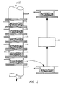
- Figure 3 is a schematic of the laboratory apparatus used in testing the invention.
- FIG. 1 a static section of the fiber filter according to the invention is shown schematically.
- High-aspect-ratio (length to thickness ratio) fibers 2 are shown in a nested relationship within a filter array 1.
- Particulate-laden fluid or waste fluid enters the filter at 3, is stripped of the particulates and/or undergoes chemical conversions of unwanted chemical species in the filter and exits at 4.
- the filter includes means for denesting the fibers at 5 of the array, means 6 for regenerating the fibers to remove the particulates or regenerating the catalyst and means for renesting the fibers in the array at 7.
- a fiber filter is a useful device for capturing particulates of about 10 microns or less.
- Small particles e.g., less than about 1 or 2 microns
- This capture depends on residence time near a fiber. For these particles, the efficiency goes down with an increase in face velocity. Larger particles are predominantly captured by impaction (impingement). This is an inertial effect which increases with an increase in face velocity.
- the geometric interception effect plays a dominant role for intermediate-sized particles and is rather independent of face velocity.
- the region A is effectively moved downward in the bed and a fresh frontal region is exposed to the dirty fluid.
- a clean filter this is accomplished by removing relatively clean fibers from the bottom of the filter array at 5 and adding them on top of the dirty fibers at 7.
- the entire region B is filled with the dirty fibers coated with particle dendrites and the only clean fibers are in region A (until they, too, capture the particulates).
- only dirty fibers are removed from the bottom. Particles are then captured throughout the bed, yielding much higher efficiencies than static filter beds of the same size.
- the dirty fibers removed from the bottom are cleaned and recycled back to the top of the bed.
- the fibers move gradually from top to bottom, i. e., in the same direction as the fluid flow through the bed. We choose to refer to this a co-current flow of fibers and fluid, though the fibers are obviously moving at a much lower velocity but in the same general direction.
- the high voidage is created by a nesting or loose packing phenomenon. It has been found that high-aspect-ratio fibers tend to nest in a rather rigid, high voidage array when they are loosely poured into a container. The nesting is really a matter of degree, but for capturing fine particles in the 1-20 micron range, fibers in the range of about 0.075 to 2 mm diameter and aspect ratios of above about 20 are preferred in the present invention. The voidage appears to vary linearly with aspect ratio of the fibers. The preferred voidage is on the order of 90-96%.
- the nesting of fibers also provides a second advantage over the packing of granules in the granular-bed filters.
- the fiber nests tend to be quite rigid compared with the loose granules.
- dendritic formations contributing to good capture are retained in the cohesive fiber bed as the bed shifts downward during operation.
- dendrites may be destroyed by the downward movement of the loose granules in a granular bed filter.
- Fibers by be made of any useful material including both organic and inorganic materials. They may merely physically capture a particulate or may react chemically with a particulate or gas.
- the fibers may also be catalytic or be coated with inert, reactant or catalytic material.
- metal fibers may have a catalytic coating to convert SO2 in flue gas to SO3 or a lime coating which can react with the SO2 to produce a CaSO4 deposit on the fiber.
- Refractory fibers as well as metal fibers, can be used for high temperature applications.
- catalytic cracking of high-boiling hydrocarbons to gaso-line fractions can take place at about 500°C with fibers made (or coated) with modified, hydrated alumina silicates. Deposited carbon would be removed by burning in air in the regenerator.
- Fibers are removed from the filter array by denesting.
- One method for denesting is shown schematically in Figure 2.
- the fibers 2 are nested in the filter container 10.
- Rotating fingers 13 denest the fibers and allow then to fall individually or in small bundles to the receiver 14.
- the fibers are then transported by any convenient means, for example, by pneumatics or conveyors 15, to the regenerator 16.
- the clean fibers are transported to a distribution means (shown as a vibrating screen 18 in Figure 2) for introduction to and nesting on the top of the existing filter array.
- the invention is not limited to the manner of denesting and it is sufficient that the method remove the fibers in a state in which they may be transported, regenerated and returned to the filter array.
- Other possible forces for denesting are gas jets, acoustic fields, magnetostrictive forces and mechanical vibration.
- dirty gas must enter into the filter array near the face where the clean fibers are added and exit near the face where dirty fibers are denested and removed. As shown in Figure 2, dirty gas enters at 11 and is removed at 19 above where fibers are denested.
- the means for regeneration will of course depend on the physical or chemical reaction that takes place in the filter bed and the condition of the fibers.
- the typical means for cleaning may comprise vibration and/or gas or liquid stripping.
- the regeneration method would generally comprise reversing the reaction.
- the regeneration would typically comprise heating the fibers to drive off the SO2 or removal of CaSO4 and recoating with CaO.
- a 9 mm thick filter bed holder consisting of two coarse screens as fiber retainers and a 7.6 cm diameter section of circular PVC duct was constructed.
- the filter array itself was nested in the holder by allowing individual stainless steel fibers to "rain” into it by free fall. Average diameter of the fibers was 25 microns and the average length was 7 mm.
- An estimate of the packing density achievable by this method of nesting gave a value of 0.025. In order to avoid tunneling, however, the settle bed during the test was manually compacted to an estimated packing density of 0.054.
- silica particles were used as the test contaminant. These particles were aerosolized with an aerosol generator and introduced to the upstream side of the filter.
- Dust loading tests were run through a fiber filter using several different fibers. Dust having an average size of 6.3 microns was passed through the fibers at about 4.7 milligrams/minute.
- Table 2 shows a consistent increase in efficiency with time and pressure as a result of the gradual filling of the matrix with dendrites.
- the present invention provides the means for using substantially the entire bed for collection and for making a continuous cleaning process, i.e. one that does not have to be shut down for periodic cleaning.
- the method for accomplishing this is to allow a buildup of particulates in the upper layer and then to successively move the layer lower in the bed by removing fibers from the bottom and recycling them (when clean) to the top. The fresh layer on the top then is built up with particulates and the process continues.
- the high voidage of the present fiber nest allows its use with high dust loadings.
- the low pressure drop allows use of smaller beds and/or higher face velocities than conventional filters.
- Type 304 stainless steel fibers were used in three sizes. Aspect ratios (L/D) were about 100. Nested-fiber properties are shown in Table 3.
- the dust used for the experiments was a standard test dust referred to as Arizona Road Dust (fine air cleaner test dust, part no. 1-543094) available from General Motors AC Spark Plug Division. This dust was classified into two mono-dispersed particle size fractions.
- the filter elements were made by dropping fibers onto a 70 mesh (200 ⁇ ) screen support.
- the elements were stacked and the dust-laden air was introduced from the top as shown in Figure 3.
- a start-up period of operation was run during which time the filter was in operation and the top element was gradually moved to the bottom by successively removing the bottom element, cleaning it and reintroducing it as the top element.
- the system is said to be at equilibrium or steady state.
- Flow and pressure readings were made every 3-6 minutes. Every 12-30 minutes, the dust feeder was turned off, the gas flow stopped and each element weighed. The elements were then returned to the stack, but were advanced one position. Time intervals were kept constant for each particular experiment. Dust size was reported as, for example, -5+1.5 ⁇ meaning that the dust particles were substantially between 1.5 and 5 microns in diameter.
Landscapes
- Chemical & Material Sciences (AREA)
- Chemical Kinetics & Catalysis (AREA)
- Filtering Of Dispersed Particles In Gases (AREA)
- Filtering Materials (AREA)
- Glass Compositions (AREA)
- Chemical Or Physical Treatment Of Fibers (AREA)
- Solid-Sorbent Or Filter-Aiding Compositions (AREA)
Claims (13)
Priority Applications (1)
| Application Number | Priority Date | Filing Date | Title |
|---|---|---|---|
| AT88900939T ATE78418T1 (de) | 1986-12-31 | 1987-12-22 | Filter mit umlaufenden fasern in wirrlage. |
Applications Claiming Priority (2)
| Application Number | Priority Date | Filing Date | Title |
|---|---|---|---|
| US948210 | 1986-12-31 | ||
| US06/948,210 US4976934A (en) | 1985-05-03 | 1986-12-31 | Nested, recirculating-fiber filter |
Publications (2)
| Publication Number | Publication Date |
|---|---|
| EP0296223A1 EP0296223A1 (de) | 1988-12-28 |
| EP0296223B1 true EP0296223B1 (de) | 1992-07-22 |
Family
ID=25487484
Family Applications (1)
| Application Number | Title | Priority Date | Filing Date |
|---|---|---|---|
| EP88900939A Expired EP0296223B1 (de) | 1986-12-31 | 1987-12-22 | Filter mit umlaufenden fasern in wirrlage |
Country Status (7)
| Country | Link |
|---|---|
| US (1) | US4976934A (de) |
| EP (1) | EP0296223B1 (de) |
| JP (1) | JPH01501850A (de) |
| AT (1) | ATE78418T1 (de) |
| CA (1) | CA1312019C (de) |
| DE (1) | DE3780631T2 (de) |
| WO (1) | WO1988004954A1 (de) |
Families Citing this family (5)
| Publication number | Priority date | Publication date | Assignee | Title |
|---|---|---|---|---|
| US4861354A (en) * | 1988-07-29 | 1989-08-29 | Battelle Memorial Institute | Removing pollutant |
| DE3921720A1 (de) * | 1989-07-01 | 1991-01-10 | Sorg Gmbh & Co Kg | Filtereinrichtung fuer staub und schwefelhaltige verbindungen enthaltende abgase von glasschmelzoefen |
| US5514399A (en) * | 1994-06-27 | 1996-05-07 | Nabisco, Inc. | Method of applying particulates to baked goods and snacks |
| US6312490B1 (en) * | 2000-01-07 | 2001-11-06 | Siemens Westinghouse Power Corporation | Interlocked fiber fail-safe regenerator device |
| GB2400330B (en) | 2003-04-10 | 2007-05-30 | Dynamic Proc Solutions Plc | Filtration apparatus |
Family Cites Families (12)
| Publication number | Priority date | Publication date | Assignee | Title |
|---|---|---|---|---|
| US1570869A (en) * | 1925-09-12 | 1926-01-26 | Thomson Thomas | Apparatus for filtering dust-laden gases |
| US2815826A (en) * | 1955-05-05 | 1957-12-10 | Frank W Young | Air filtration |
| US3151187A (en) * | 1959-04-23 | 1964-09-29 | Alsacienne Constr Meca | Fluid filtering system |
| US3708210A (en) * | 1971-07-26 | 1973-01-02 | Rieter Ag Maschf | Method and apparatus for separating opened fiber flocks from an air stream |
| US4110081A (en) * | 1977-06-09 | 1978-08-29 | Uop Inc. | Moving-bed radial flow solids-fluid contacting apparatus |
| GB2016432B (en) * | 1978-03-17 | 1982-11-24 | Hoelter H | Metal oxide-coated coated silica fibres hot gas filter |
| DE2828130A1 (de) * | 1978-06-27 | 1980-01-10 | Duerr Otto Anlagen Gmbh | Verfahren zur reinigung der abluft aus einer lackspritzanlage |
| US4227899A (en) * | 1978-09-06 | 1980-10-14 | Meny Allan H | Absolute fluid filter |
| JPS6037047B2 (ja) * | 1979-03-09 | 1985-08-23 | 住友重機械工業株式会社 | 脱硫用活性炭の再生法 |
| US4229187A (en) * | 1979-04-09 | 1980-10-21 | Gamewell Manufacturing, Inc. | Movable, continuously changing, self-charging electrostatic filter |
| DE3246183A1 (de) * | 1982-05-06 | 1983-11-10 | Adolf Dipl.-Ing. 3060 Stadthagen Margraf | Schuettgutschichtfilter |
| DE3313943A1 (de) * | 1982-05-13 | 1983-11-17 | Delbag-Luftfilter Gmbh, 1000 Berlin | Verfahren und vorrichtung zum kontinuierlichen austausch von in einem chemischen und/oder physikalischen vorgang, wie z. b. einem filter-, einem adsorptions- oder trockenvorgang, verbrauchten regenerierbaren kontaktmitteln, wie filtermaterialien, trockenmitteln, adsorbermaterialien oder katalysatoren |
-
1986
- 1986-12-31 US US06/948,210 patent/US4976934A/en not_active Expired - Fee Related
-
1987
- 1987-12-22 JP JP63501099A patent/JPH01501850A/ja active Pending
- 1987-12-22 AT AT88900939T patent/ATE78418T1/de not_active IP Right Cessation
- 1987-12-22 DE DE8888900939T patent/DE3780631T2/de not_active Expired - Lifetime
- 1987-12-22 WO PCT/US1987/003469 patent/WO1988004954A1/en not_active Ceased
- 1987-12-22 EP EP88900939A patent/EP0296223B1/de not_active Expired
- 1987-12-30 CA CA000555548A patent/CA1312019C/en not_active Expired - Lifetime
Also Published As
| Publication number | Publication date |
|---|---|
| WO1988004954A1 (en) | 1988-07-14 |
| CA1312019C (en) | 1992-12-29 |
| EP0296223A1 (de) | 1988-12-28 |
| DE3780631D1 (de) | 1992-08-27 |
| JPH01501850A (ja) | 1989-06-29 |
| US4976934A (en) | 1990-12-11 |
| DE3780631T2 (de) | 1992-12-24 |
| ATE78418T1 (de) | 1992-08-15 |
Similar Documents
| Publication | Publication Date | Title |
|---|---|---|
| CA1156937A (en) | Filter apparatus and method for collecting fly ash and fine dust | |
| KR100348168B1 (ko) | 필터와 정전기적 분리기의 조합 | |
| US4973459A (en) | Apparatus and method for removing gaseous contaminants and particulate contaminants from a hot gas stream | |
| US4650647A (en) | Apparatus for removing acid constituents from waste-gas | |
| US4374652A (en) | Filter apparatus and method for collecting fly ash and fine dust | |
| US4140502A (en) | Filtering separators with dust feedback | |
| US3892543A (en) | Method of the removal of chemically active components from dust-laden gas streams | |
| US4300921A (en) | Apparatus and method for removing finely divided solids from gases | |
| EP0296223B1 (de) | Filter mit umlaufenden fasern in wirrlage | |
| US4360364A (en) | Filtering method and apparatus therefor | |
| GB2035128A (en) | Filtering apparatus and method | |
| CA1260406A (en) | Dust pre-removal method in a dry moving bed type adsorption tower | |
| US6440198B1 (en) | Cost effective moving granular bed filters for particulates and contaminants removal | |
| US4452613A (en) | Vertical media bed filter and method of cleaning filter panels | |
| US6149697A (en) | Removal of suspended fine particles from gases by turbulent deposition | |
| JPH0742488Y2 (ja) | 移動床型脱じん・反応装置 | |
| Smid et al. | Granular moving bed filters and adsorbers (GM-BF/A)—patent review: 1970-2000 | |
| US3957953A (en) | Treating gas with catalytic dust in panel bed | |
| US5186917A (en) | Process for the removal of nox sox utilizing a particulate agent | |
| JPS59183817A (ja) | 廃棄物焼却炉排ガス中の有害成分・ダスト除去方法 | |
| US4861354A (en) | Removing pollutant | |
| CA2045146A1 (en) | Filter for separating particles from gases | |
| CN1072025C (zh) | 表面过滤板颗粒移动床过滤方法及其设备 | |
| Seville et al. | Granular bed filters | |
| NZ239236A (en) | Toroidal gas scrubber for aluminium potline exhaust gas achieves high sorption rate with fine fraction of alumina feed |
Legal Events
| Date | Code | Title | Description |
|---|---|---|---|
| PUAI | Public reference made under article 153(3) epc to a published international application that has entered the european phase |
Free format text: ORIGINAL CODE: 0009012 |
|
| 17P | Request for examination filed |
Effective date: 19880826 |
|
| AK | Designated contracting states |
Kind code of ref document: A1 Designated state(s): AT BE CH DE FR GB IT LI LU NL SE |
|
| 17Q | First examination report despatched |
Effective date: 19910320 |
|
| GRAA | (expected) grant |
Free format text: ORIGINAL CODE: 0009210 |
|
| AK | Designated contracting states |
Kind code of ref document: B1 Designated state(s): AT BE CH DE FR GB IT LI LU NL SE |
|
| REF | Corresponds to: |
Ref document number: 78418 Country of ref document: AT Date of ref document: 19920815 Kind code of ref document: T |
|
| REF | Corresponds to: |
Ref document number: 3780631 Country of ref document: DE Date of ref document: 19920827 |
|
| ITF | It: translation for a ep patent filed | ||
| ET | Fr: translation filed | ||
| ITTA | It: last paid annual fee | ||
| REG | Reference to a national code |
Ref country code: GB Ref legal event code: 732E |
|
| PLBE | No opposition filed within time limit |
Free format text: ORIGINAL CODE: 0009261 |
|
| STAA | Information on the status of an ep patent application or granted ep patent |
Free format text: STATUS: NO OPPOSITION FILED WITHIN TIME LIMIT |
|
| 26N | No opposition filed | ||
| PGFP | Annual fee paid to national office [announced via postgrant information from national office to epo] |
Ref country code: FR Payment date: 19931109 Year of fee payment: 7 |
|
| PGFP | Annual fee paid to national office [announced via postgrant information from national office to epo] |
Ref country code: CH Payment date: 19931112 Year of fee payment: 7 |
|
| PGFP | Annual fee paid to national office [announced via postgrant information from national office to epo] |
Ref country code: LU Payment date: 19931116 Year of fee payment: 7 |
|
| PGFP | Annual fee paid to national office [announced via postgrant information from national office to epo] |
Ref country code: SE Payment date: 19931117 Year of fee payment: 7 Ref country code: AT Payment date: 19931117 Year of fee payment: 7 |
|
| PGFP | Annual fee paid to national office [announced via postgrant information from national office to epo] |
Ref country code: DE Payment date: 19931124 Year of fee payment: 7 Ref country code: BE Payment date: 19931124 Year of fee payment: 7 |
|
| PGFP | Annual fee paid to national office [announced via postgrant information from national office to epo] |
Ref country code: GB Payment date: 19931129 Year of fee payment: 7 |
|
| EPTA | Lu: last paid annual fee | ||
| PGFP | Annual fee paid to national office [announced via postgrant information from national office to epo] |
Ref country code: NL Payment date: 19931231 Year of fee payment: 7 |
|
| PG25 | Lapsed in a contracting state [announced via postgrant information from national office to epo] |
Ref country code: LU Free format text: LAPSE BECAUSE OF NON-PAYMENT OF DUE FEES Effective date: 19941222 Ref country code: GB Effective date: 19941222 Ref country code: AT Effective date: 19941222 |
|
| PG25 | Lapsed in a contracting state [announced via postgrant information from national office to epo] |
Ref country code: SE Effective date: 19941223 |
|
| PG25 | Lapsed in a contracting state [announced via postgrant information from national office to epo] |
Ref country code: LI Effective date: 19941231 Ref country code: CH Effective date: 19941231 Ref country code: BE Effective date: 19941231 |
|
| EAL | Se: european patent in force in sweden |
Ref document number: 88900939.5 |
|
| BERE | Be: lapsed |
Owner name: BATTELLE MEMORIAL INSTITUTE Effective date: 19941231 |
|
| PG25 | Lapsed in a contracting state [announced via postgrant information from national office to epo] |
Ref country code: NL Effective date: 19950701 |
|
| GBPC | Gb: european patent ceased through non-payment of renewal fee |
Effective date: 19941222 |
|
| PG25 | Lapsed in a contracting state [announced via postgrant information from national office to epo] |
Ref country code: FR Effective date: 19950831 |
|
| REG | Reference to a national code |
Ref country code: CH Ref legal event code: PL |
|
| NLV4 | Nl: lapsed or anulled due to non-payment of the annual fee |
Effective date: 19950701 |
|
| PG25 | Lapsed in a contracting state [announced via postgrant information from national office to epo] |
Ref country code: DE Effective date: 19950901 |
|
| EUG | Se: european patent has lapsed |
Ref document number: 88900939.5 |
|
| REG | Reference to a national code |
Ref country code: FR Ref legal event code: ST |
|
| PG25 | Lapsed in a contracting state [announced via postgrant information from national office to epo] |
Ref country code: IT Free format text: LAPSE BECAUSE OF NON-PAYMENT OF DUE FEES;WARNING: LAPSES OF ITALIAN PATENTS WITH EFFECTIVE DATE BEFORE 2007 MAY HAVE OCCURRED AT ANY TIME BEFORE 2007. THE CORRECT EFFECTIVE DATE MAY BE DIFFERENT FROM THE ONE RECORDED. Effective date: 20051222 |