EP0294561A2 - Operating mechanism for a circuit breaker - Google Patents
Operating mechanism for a circuit breaker Download PDFInfo
- Publication number
- EP0294561A2 EP0294561A2 EP88105869A EP88105869A EP0294561A2 EP 0294561 A2 EP0294561 A2 EP 0294561A2 EP 88105869 A EP88105869 A EP 88105869A EP 88105869 A EP88105869 A EP 88105869A EP 0294561 A2 EP0294561 A2 EP 0294561A2
- Authority
- EP
- European Patent Office
- Prior art keywords
- operating mechanism
- large gear
- circuit breaker
- closing
- gear
- Prior art date
- Legal status (The legal status is an assumption and is not a legal conclusion. Google has not performed a legal analysis and makes no representation as to the accuracy of the status listed.)
- Withdrawn
Links
Images



Classifications
-
- H—ELECTRICITY
- H01—ELECTRIC ELEMENTS
- H01H—ELECTRIC SWITCHES; RELAYS; SELECTORS; EMERGENCY PROTECTIVE DEVICES
- H01H3/00—Mechanisms for operating contacts
- H01H3/22—Power arrangements internal to the switch for operating the driving mechanism
- H01H3/30—Power arrangements internal to the switch for operating the driving mechanism using spring motor
- H01H3/3005—Charging means
-
- H—ELECTRICITY
- H01—ELECTRIC ELEMENTS
- H01H—ELECTRIC SWITCHES; RELAYS; SELECTORS; EMERGENCY PROTECTIVE DEVICES
- H01H3/00—Mechanisms for operating contacts
- H01H3/22—Power arrangements internal to the switch for operating the driving mechanism
- H01H3/30—Power arrangements internal to the switch for operating the driving mechanism using spring motor
- H01H2003/3063—Decoupling charging handle or motor at end of charging cycle or during charged condition
-
- H—ELECTRICITY
- H01—ELECTRIC ELEMENTS
- H01H—ELECTRIC SWITCHES; RELAYS; SELECTORS; EMERGENCY PROTECTIVE DEVICES
- H01H3/00—Mechanisms for operating contacts
- H01H3/22—Power arrangements internal to the switch for operating the driving mechanism
- H01H3/30—Power arrangements internal to the switch for operating the driving mechanism using spring motor
- H01H2003/3094—Power arrangements internal to the switch for operating the driving mechanism using spring motor allowing an opening - closing - opening [OCO] sequence
-
- H—ELECTRICITY
- H01—ELECTRIC ELEMENTS
- H01H—ELECTRIC SWITCHES; RELAYS; SELECTORS; EMERGENCY PROTECTIVE DEVICES
- H01H3/00—Mechanisms for operating contacts
- H01H3/22—Power arrangements internal to the switch for operating the driving mechanism
- H01H3/30—Power arrangements internal to the switch for operating the driving mechanism using spring motor
- H01H3/3005—Charging means
- H01H3/3026—Charging means in which the closing spring charges the opening spring or vice versa
-
- H—ELECTRICITY
- H01—ELECTRIC ELEMENTS
- H01H—ELECTRIC SWITCHES; RELAYS; SELECTORS; EMERGENCY PROTECTIVE DEVICES
- H01H3/00—Mechanisms for operating contacts
- H01H3/22—Power arrangements internal to the switch for operating the driving mechanism
- H01H3/30—Power arrangements internal to the switch for operating the driving mechanism using spring motor
- H01H3/3042—Power arrangements internal to the switch for operating the driving mechanism using spring motor using a torsion spring
Definitions
- the present invention relates to an operating mechanism for switching a circuit breaker.
- Operating duty of a power circuit breaker is O-0.35sec-CO-1min-CO for a high speed switch.
- reference O designates open-circuit operation
- CO designates open-circuit operation following closing-circuit operation without a spare time
- Fig. 1 through 3 are views showing the conventional spring operation mechanism in construction, in which Fig. 1 shows a closed-circuit condition, Fig. 2 an open-circuit condition, and Fig. 3 shows de-energized condition of a closing spring.
- a reference numeral 100 designates a movable contact for the circuit breaker
- 109 designates a lever for controlling switching operation of the movable contact 100, the movable contact 100 being connected to the utmost end of a projection at the central portion of lever 109.
- a roller 109a engageable with a cam 101 to be discussed below and for actuating the lever 109.
- the lever 109 is connected at one end thereof to an open spring 103 and provided at the other end thereof with a pin 104 engageable with a trip latch 106.
- the cam 101 is fixed to a cam shaft 108 coaxially with a ratchet wheel 107, and a closing spring 102 for biasing the ratchet wheel 107 is connected thereto, the cam 101, ratchet wheel 107 and cam shaft 108 being integrally fixed by deenergizing the closing spring 102 and rotating together.
- a pin 118 At the ratchet wheel 107 is provided with a pin 118, with which engages a closing latch 111 retained by a closing trigger 110 retained or actuated by a plunger 112 actuated by a closing magnet 113.
- the ratchet wheel 107 has at the outer periphery thereof a portion provided with no ratchet teeth.
- trip latch 106 retained by a trip trigger 105 retained or actuated by a plunger 116 actuated by a trip magnet 117 engages with the pin 104 provided at one end of the lever 109.
- a reference numeral 114 designates a pawl shaft connected to a drive source through a gear (not shown).
- the pawl shaft 114 is provided with two eccentric pawls 115 and rotates to move the pawls 115 in swinging motion, thereby rotating the ratchet wheel 107.
- the open-circuit operation will be described, in which the lever 109 is normally given a clockwise torque (in the direction of the arrow B) by a leftward (in the direction of the arrow A) urging force of the energized open spring 103, the torque B being held by retaining the pin 104 by the trip latch 106 and the trip trigger 105.
- Fig. 2 shows the completed open-circuit operation.
- a closing spring 102 connected to the ratchet wheel 107 is biased to give to a cam shaft 108 a clockwise torque (in the direction of the arrow D), but a closing latch 111 engaging with a pin 118 provided at the ratchet wheel 107 and a closing trigger 110 retaining the closing latch 111 restrain the ratchet wheel 107 from rotation.
- the closing electromagnet 113 is energized to move the plunger 112 leftwardly (in the direction of the arrow E)
- the closing trigger 110 rotates counterclockwise (in the direction of the arrow F), whereby the closing latch 111 releases the engagement of the pin 118.
- Fig. 3 shows the state where the clos ing operation is completed and the pin 104 is again retained to the trip latch 106.
- the closing spring 102 is in deenergized condition.
- the drive source is started to rotate the pawl shaft 114. Since the pawl shaft 114 is eccentric, the two pawls 115 carry out swinging motion, whereby the ratchet wheel 107 rotates clockwise (in the direction of the arrow H) to energize the closing spring 102, and at this time the cam shaft 108 is given a clockwise torque (in the direction of the arrow H) at the position beyond the upper dead-point of the ratch wheel 107 of the closing spring 102, the torque being held by engagement of the pin 118 with the closing latch 111 and then the state shown in Fig. 1 is again obtained.
- the conventional spring operating mechanism is constituted as above-mentioned, so that when the drive source rotates the pawl shaft 114 to swing the pawls 115, a load with respect to the drive source pulsates. Accordingly, the energy efficiency of the drive source is poor, resulting in that the problem is created in that a drive source larger in capacity is required. Also, the pawl 115 is obliged to be pointed at the tip. Hence, the above-mentioned mechanism cannot be applied to the spring operating mechanism of a large spring load.
- a first object of the invention is to provide an operating mechanism for the circuit breaker, in which an energy conserving apparatus for the open spring and closing spring is provided with a large gear lacking in teeth in part and a small gear engageable with the large gear, the no tooth portion at the large gear being provided at the position where the large gear disengages from the small gear just after the energy conservation of the closing spring has been completed.
- an energy conserving apparatus for the open spring and closing spring is provided with a large gear lacking in teeth in part and a small gear engageable with the large gear, the no tooth portion at the large gear being provided at the position where the large gear disengages from the small gear just after the energy conservation of the closing spring has been completed.
- a second object of the present invention is to provide an operating mechanism for a circuit breaker which is pro vided at the large gear with a reengagement mechanism with respect to the small gear, whereby as module of gear is desir-ably selectable to conserve energy in a spring of large capacity, resulting in that an operating mechanism of a large circuit and large capacity.
- a third object of the present invention is to provide an operating mechanism for a circuit breaker wherein the reengagement mechanism is provided with a plunger having the utmost end of the same tooth form as the small gear, thereby enabling the large gear and the small gear to be soothly reengaged.
- Fig. 4 shows the closed-circuit condition thereof
- Fig. 5 the open-circuit condition
- Fig. 6 is a closing spring in deenergized condition.
- a lever 2 is pivotally supported on a rotary main shaft 1 and fixes at the inside of the lever 2 one end of open torsion bar 3 of the closing spring, so that the rotary main shaft 1, in turn the lever 2, is given a counterclockwise torque (in the direction of the arrow a, by an elastic force of open torsion bar 3.
- the lever 2 is provided with a roller 10, and a cam 11 for rotating the lever 2 through the roller 10 is provided in relation of being connected with a large gear 8 to be discussed below through a cam shaft 12, the cam 11 and large gear 8 integrally rotating.
- a closing lever 4 pivotally supported on a closing main shaft 6 and rotatably pin-connected at the utmost end with a link 5, the large gear 8 being pivotally supported rotatably on the closing lever 4 (link 5).
- a closing torsion bar 7 of closing spring is fixed at one end on the inside of closing main shaft 6 so that the closing main shaft 6 is given a counterclockwise torque (in the direction of the arrow b) by an elastic force of the closing torsion bar 7.
- a small gear 9 connected to the drive source through a gear (not shown) is provided in relation of engaging with the large gear 8.
- the large gear 8 lacks in teeth in part so that at the position where the closing torsion bar 7 conserves energy the small gear 9 corresponds to a non-tooth portion 8a of the large gear 8, thereby not engaging therewith.
- a bore 20 extending radially on the pitch of teeth, and into the bore 20 a plunger 14 tooth-formed at the utmost end is provided in relation of freely projecting or retracting through a spring 13 and guided by a guide 15, the plunger 14 being formed to engage with the small gear 9.
- lever 2 connects with a buffer 16 for buffering an impact caused by the open or the closing operation.
- a movable contact 100 is in an arc extinguish chamber and connected to the lever 2 through a linkage mechanism (not shown).
- the components designated by reference numerals 104 to 106, 110 to 113 and 116 to 118 are the same as or corresponding to those in the conventional apparatus, which are omitted of explanation herein.
- the trip latch 106 and trip trigger 105 hold a torque (in the direction of the arrow a) given to the lever 2. Accordingly, when a trip electromagnet 117 is energized in this state, a plunger 116 thereof moves rightwardly (in the direction of the arrow c), the trip trigger 105 rotates clockwise (in the direction of the arrow d), and the trip latch 106 rotates counterclockwise (in the direction of the arrow e) by reaction from a pin 104.
- Fig. 5 shows completion of such operation. Next, explanation will be given on closing operation.
- the cam 11 rotates clockwise (in the direction of the arrow f) by an elastic force of the closing torsion bar 7 through the closing lever 4 and link 5, thereby pushing up the roller 10 provided at the lever 2.
- the lever 2 twists the open torsion bar 3 clockwise (in the direction of the arrow j) and closes the movable contact 100.
- Fig. 6 shows the state where the closing operation is completed and the pin 104 again engages with the trip latch 106 and is held thereto.
- closing torsion bar 7 is deenergized while energizing the open torsion bar 3, whereby the conserved energy of closing torsion bar 7 is larger than that of open torsion bar 3.
- the closing torsion bar 7 is in the state of deenergization just after the closing operation has been completed.
- the small gear 9 rotates counter clockwise (in the direction of the arrow k) by the drive source (not shown) so that the large gear 8 in engagement with the small gear 9 rotates clockwise (in the direction of the arrow l).
- the closing torsion bar 7 rotates clockwise (in the direction of the arrow m) through the link 5, closing lever 4 and closing main shaft 6 and conserves energy.
- the cam shaft 12 At the position beyond the dead point where the direction of a tensile load of link 5 intersects the center of cam shaft 12, the cam shaft 12 is given a clockwise torque by an elastic force of the closing torsion bar 7 through the link 5, and simultaneously the small gear 9 corresponds to the non-tooth portion 8a of the large gear 8, thereby disengaging therefrom.
- both the large gear 8 and small gear 9 use a spur gear respectively, but they may alternatively use a helical gear or a bevel gear.
- the closing torsion bar and open torsion bar are used as the closing spring and open spring, but a coil spring or a spiral spring may alternatively be used, or other springs may be used. In either case, the same effect as the aforesaid embodiment is obtained.
- the energy conserving apparatus of the closing spring is fixed coaxially with the cam, the large gear lacking in teeth in part and the small gear engageable with the large gear and rotatably driven by the drive source are provided to form the non-tooth portion at the portion of large gear where the small gear disengages therefrom just after completion of energy conservation of the closing circuit spring, and both the gears are adapted to smoothly engage with each other, whereby the load on the drive source is free from pulsation and the drive source of small capacity is enough for use.
- a module of the gear can desirably be selected, thereby enabling the large capacity spring to conserve energy and not applying an overload on the gear.
- an operating mechanism for the circuit breaker inexpensive to produce and of a large current and a large capacity is obtainable.
Landscapes
- Driving Mechanisms And Operating Circuits Of Arc-Extinguishing High-Tension Switches (AREA)
Abstract
The present invention relates to an operating mechanism for a circuit breaker; having an opening means (3) carrying out open-circuit operation by deenergization thereof and a closing means (7) carrying out closing-circuit operation by rotation of a cam (11) caused by deenergization of the closing means so that the opening means conserves energy by deenergization of the closing means and the closing means conserves energy by rotation of the cam; and the operating mechanism according to the present invention is provided with a large gear (8) fixed coaxially with the cam and lacking in teeth in part (8a) and a small gear (9) rotatably driven by a drive source in relation of engaging with the large gear, so that the non-tooth portion of the large gear is provided at the position thereof where the large gear disengages from the small gear just after the closing means completes its energy conservation, whereby the small gear, after completion of energy conservation of the closing means is completed, runs idle in the non-tooth portion and the drive source for the small gear is free from pulsation of a load and the drive source smoothly rotates, resulting in that a small drive source is enough for use and the large gear and small gear are not subjected to an overload, thereby the present invention can provide an operating mechanism of a large current and a large capacity.
Description
- The present invention relates to an operating mechanism for switching a circuit breaker.
- Operating duty of a power circuit breaker, as disclosed in JEC-2300 (Japanese Electrotechnical Commission-2300), is O-0.35sec-CO-1min-CO for a high speed switch.
- Herein, reference O designates open-circuit operation, and CO designates open-circuit operation following closing-circuit operation without a spare time.
- Therefore, it is necessary for the operating mechanism for the circuit breaker to conserve, before the initial open-operation, energy for at least O-0.35sec-CO operation, that is, two times open-operation and one time closing-operation, because for the next 1 min there is means for conserving energy of CO, but it is difficult to conserve large energy for 0.35 sec.
- There is another operating duty of CO-15sec-CO, in which, when the energy needful to CO can be conserved for 15 second, the operating duty is completed.
- For example, the conventional examples disclosed in the Japanese Utility Model Laid-Open Gazette No. 59-85546 (1985) and the Japanese Patent Laid-Open Gazette No. 61-96619 (1987) are designed to satisfy the aforesaid operating duty.
- Next, explanation will be given on the conventional apparatus satisfying the aforesaid operating duty.
- Fig. 1 through 3 are views showing the conventional spring operation mechanism in construction, in which Fig. 1 shows a closed-circuit condition, Fig. 2 an open-circuit condition, and Fig. 3 shows de-energized condition of a closing spring.
- In the drawing, a
reference numeral 100 designates a movable contact for the circuit breaker, and 109 designates a lever for controlling switching operation of themovable contact 100, themovable contact 100 being connected to the utmost end of a projection at the central portion oflever 109. At the center oflever 109 is provided aroller 109a engageable with acam 101 to be discussed below and for actuating thelever 109. Thelever 109 is connected at one end thereof to anopen spring 103 and provided at the other end thereof with apin 104 engageable with atrip latch 106. - The
cam 101 is fixed to acam shaft 108 coaxially with aratchet wheel 107, and aclosing spring 102 for biasing theratchet wheel 107 is connected thereto, thecam 101,ratchet wheel 107 andcam shaft 108 being integrally fixed by deenergizing theclosing spring 102 and rotating together. At theratchet wheel 107 is provided with apin 118, with which engages aclosing latch 111 retained by aclosing trigger 110 retained or actuated by aplunger 112 actuated by aclosing magnet 113. In addition, theratchet wheel 107 has at the outer periphery thereof a portion provided with no ratchet teeth. - The
trip latch 106 retained by atrip trigger 105 retained or actuated by aplunger 116 actuated by atrip magnet 117 engages with thepin 104 provided at one end of thelever 109. - Also, a
reference numeral 114 designates a pawl shaft connected to a drive source through a gear (not shown). Thepawl shaft 114 is provided with twoeccentric pawls 115 and rotates to move thepawls 115 in swinging motion, thereby rotating theratchet wheel 107. - Next, explanation will be given in operation of the conventional apparatus.
- Referring to Fig. 1, the open-circuit operation will be described, in which the
lever 109 is normally given a clockwise torque (in the direction of the arrow B) by a leftward (in the direction of the arrow A) urging force of the energizedopen spring 103, the torque B being held by retaining thepin 104 by thetrip latch 106 and thetrip trigger 105. - Accordingly, when the
trip magnet 117 is energized to project theplunger 116 leftwardly in the direction of the arrow C), the trip trigger 105 rotates counterclockwise. Hence, thetrip latch 106 disengages from thepin 104, resulting in that thelever 109 rotates clockwise (in the direction of the arrow B) by the afore-said torque to open themovable contact 100, thereby breaking the circuit. - Fig. 2 shows the completed open-circuit operation.
- Next, explanation will be given on closing-circuit operation.
- In Fig. 2, a
closing spring 102 connected to theratchet wheel 107 is biased to give to a cam shaft 108 a clockwise torque (in the direction of the arrow D), but aclosing latch 111 engaging with apin 118 provided at theratchet wheel 107 and aclosing trigger 110 retaining theclosing latch 111 restrain theratchet wheel 107 from rotation. In such state, when theclosing electromagnet 113 is energized to move theplunger 112 leftwardly (in the direction of the arrow E), theclosing trigger 110 rotates counterclockwise (in the direction of the arrow F), whereby theclosing latch 111 releases the engagement of thepin 118. - Then, the
cam 101 rotates clockwise by a torque D and theroller 109a is pushed by thecam 101 to rotate counterclockwise (in the direction of the arrow G). As a result, thelever 109 compresses theopen spring 103 and closes themovable contact 100. Fig. 3 shows the state where the clos ing operation is completed and thepin 104 is again retained to thetrip latch 106. - Next, explanation will be given on energy conserving operation of the
closing spring 102. - As shown in Fig. 3, just after completion of closing operation, the
closing spring 102 is in deenergized condition. In this case, the drive source is started to rotate thepawl shaft 114. Since thepawl shaft 114 is eccentric, the twopawls 115 carry out swinging motion, whereby theratchet wheel 107 rotates clockwise (in the direction of the arrow H) to energize theclosing spring 102, and at this time thecam shaft 108 is given a clockwise torque (in the direction of the arrow H) at the position beyond the upper dead-point of theratch wheel 107 of theclosing spring 102, the torque being held by engagement of thepin 118 with theclosing latch 111 and then the state shown in Fig. 1 is again obtained. - In addition, in the state shown in Fig. 1, since the two
pawls 115 correspond to the no tooth portion at theratchet wheel 107, even when thepawls 115 swing, theratchet wheel 107 is given no torque, so that thepawl shaft 114 is idle and an overload caused by the rotation of drive source is not given to thepawls 115 or closinglatch 111. - The conventional spring operating mechanism, however, is constituted as above-mentioned, so that when the drive source rotates the
pawl shaft 114 to swing thepawls 115, a load with respect to the drive source pulsates. Accordingly, the energy efficiency of the drive source is poor, resulting in that the problem is created in that a drive source larger in capacity is required. Also, thepawl 115 is obliged to be pointed at the tip. Hence, the above-mentioned mechanism cannot be applied to the spring operating mechanism of a large spring load. - The present invention has been designed to solve the above problem. A first object of the invention is to provide an operating mechanism for the circuit breaker, in which an energy conserving apparatus for the open spring and closing spring is provided with a large gear lacking in teeth in part and a small gear engageable with the large gear, the no tooth portion at the large gear being provided at the position where the large gear disengages from the small gear just after the energy conservation of the closing spring has been completed. Hence, pulsation of the load on the small gear with respect to a drive source thereof can be reduced, whereby a drive source of small capacity is enough for use.
- A second object of the present invention is to provide an operating mechanism for a circuit breaker which is pro vided at the large gear with a reengagement mechanism with respect to the small gear, whereby as module of gear is desir-ably selectable to conserve energy in a spring of large capacity, resulting in that an operating mechanism of a large circuit and large capacity.
- A third object of the present invention is to provide an operating mechanism for a circuit breaker wherein the reengagement mechanism is provided with a plunger having the utmost end of the same tooth form as the small gear, thereby enabling the large gear and the small gear to be soothly reengaged.
- The above and further objects and features of the invention will more fully be apparent from the following detailed description with accompanying drawings.
-
- Fig. 1 is a structural view of the conventional spring operating mechanism in a closed-circuit condition,
- Fig. 2 is a structural view of the conventional spring operating mechanism in an open-circuit condition,
- Fig. 3 is a structural view of the conventional spring operating mechanism when a closing spring is deenergized,
- Fig. 4 is a structural view of an embodiment of a spring operating mechanism of the invention in a state of closed-circuit,
- Fig. 5 is a is a structural view of the spring operating mechanism of the invention in a state of open-circuit,
- Fig. 6 is a structural view of the spring operating mechanism of the invention when a closing spring is deenergized, and
- Fig. 7 is a partially enlarged view of Fig. 4 embodiment.
- Next, an embodiment of a circuit breaker of the invention will be concretely described.
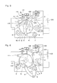
- Fig. 4 shows the closed-circuit condition thereof, Fig. 5 the open-circuit condition, and Fig. 6 is a closing spring in deenergized condition.
- In the drawing, a
lever 2 is pivotally supported on a rotary main shaft 1 and fixes at the inside of thelever 2 one end ofopen torsion bar 3 of the closing spring, so that the rotary main shaft 1, in turn thelever 2, is given a counterclockwise torque (in the direction of the arrow a, by an elastic force ofopen torsion bar 3. Also, thelever 2 is provided with aroller 10, and a cam 11 for rotating thelever 2 through theroller 10 is provided in relation of being connected with alarge gear 8 to be discussed below through acam shaft 12, the cam 11 andlarge gear 8 integrally rotating. - A
closing lever 4 pivotally supported on a closingmain shaft 6 and rotatably pin-connected at the utmost end with alink 5, thelarge gear 8 being pivotally supported rotatably on the closing lever 4 (link 5). Aclosing torsion bar 7 of closing spring is fixed at one end on the inside of closingmain shaft 6 so that the closingmain shaft 6 is given a counterclockwise torque (in the direction of the arrow b) by an elastic force of theclosing torsion bar 7. - A
small gear 9 connected to the drive source through a gear (not shown) is provided in relation of engaging with thelarge gear 8. Thelarge gear 8 lacks in teeth in part so that at the position where theclosing torsion bar 7 conserves energy thesmall gear 9 corresponds to anon-tooth portion 8a of thelarge gear 8, thereby not engaging therewith. - Also, as shown in Fig. 7, at the
non-tooth portion 8a of thelarge gear 8 is formed abore 20 extending radially on the pitch of teeth, and into the bore 20 aplunger 14 tooth-formed at the utmost end is provided in relation of freely projecting or retracting through aspring 13 and guided by aguide 15, theplunger 14 being formed to engage with thesmall gear 9. - Furthermore, the
lever 2 connects with abuffer 16 for buffering an impact caused by the open or the closing operation. - In addition, a
movable contact 100 is in an arc extinguish chamber and connected to thelever 2 through a linkage mechanism (not shown). Also, the components designated byreference numerals 104 to 106, 110 to 113 and 116 to 118 are the same as or corresponding to those in the conventional apparatus, which are omitted of explanation herein. - Next, explanation will be given on operation of the circuit breaker of the invention, at first on the open operation.
- As shown in Fig. 4, the
trip latch 106 andtrip trigger 105 hold a torque (in the direction of the arrow a) given to thelever 2. Accordingly, when atrip electromagnet 117 is energized in this state, aplunger 116 thereof moves rightwardly (in the direction of the arrow c), thetrip trigger 105 rotates clockwise (in the direction of the arrow d), and thetrip latch 106 rotates counterclockwise (in the direction of the arrow e) by reaction from apin 104. - When the
trip latch 106 disengages from thepin 104, thelever 2 rotates counterclockwise (in the direction of the arrow a) by a force of theopen torsion bar 3, so that themovable contact 100 in the arc extinction chamber is driven in the direction of open whereby the circuit is open. - Fig. 5 shows completion of such operation. Next, explanation will be given on closing operation.
- As shown in Fig. 5, since the cam 11 is connected to the closing
lever 4 through thecam shaft 12,large gear 8 andlink 5, an elastic force of the closingtorsion bar 7 gives a clockwise torque (in the direction of the arrow f) to the cam 11, the torque being held by aclosing latch 111 andclosing trigger 110. - In this state, when a
closing electromagnet 113 is energized, aplunger 112 thereof moves rightwardly (in the direction of the arrow g) and aclosing trigger 110 rotates clockwise (in the direction of the arrow h). As a result, theclosing latch 111 is released from theclosing trigger 110 and rotates counterclockwise (in the direction of the arrow i) by reaction from apin 118. - When the
closing latch 111 disengages from thepin 118, the cam 11 rotates clockwise (in the direction of the arrow f) by an elastic force of the closingtorsion bar 7 through the closinglever 4 andlink 5, thereby pushing up theroller 10 provided at thelever 2. Thelever 2 twists theopen torsion bar 3 clockwise (in the direction of the arrow j) and closes themovable contact 100. - Fig. 6 shows the state where the closing operation is completed and the
pin 104 again engages with thetrip latch 106 and is held thereto. - In addition, the closing
torsion bar 7 is deenergized while energizing theopen torsion bar 3, whereby the conserved energy of closingtorsion bar 7 is larger than that ofopen torsion bar 3. - Next, explanation will be given on energy conserving operation of the closing
torsion bar 7. As shown in Fig. 6, the closingtorsion bar 7 is in the state of deenergization just after the closing operation has been completed. Thesmall gear 9 rotates counter clockwise (in the direction of the arrow k) by the drive source (not shown) so that thelarge gear 8 in engagement with thesmall gear 9 rotates clockwise (in the direction of the arrow l). Then, the closingtorsion bar 7 rotates clockwise (in the direction of the arrow m) through thelink 5, closinglever 4 and closingmain shaft 6 and conserves energy. At the position beyond the dead point where the direction of a tensile load oflink 5 intersects the center ofcam shaft 12, thecam shaft 12 is given a clockwise torque by an elastic force of the closingtorsion bar 7 through thelink 5, and simultaneously thesmall gear 9 corresponds to thenon-tooth portion 8a of thelarge gear 8, thereby disengaging therefrom. - The clockwise torque (in the direction of the arrow l) of
large gear 8 by an elastic force of closingtorsion bar 7 is held by engaging of thepin 118 with theclosing latch 111, that is, the spring operating mechanism is restored to the state shown in Fig. 4. In this state, thesmall gear 9 disengages from thelarge gear 8 so that, even when the drive source is driven, thesmall gear 9 is idle within thenon-tooth portion 8a of thelarge gear 8. Hence, thelarge gear 8 is not given a driving force from the drive source, thereby preventing theclosing latch 111 and pin 118 from being subjected to an excessive load. - In the initial period of circuit-closing operation, when the
large gear 8 and thesmall gear 9 begin to engage with each other at thenon-tooth portion 8a, teeth of bothgears small gear 9 interfere with theplunger 14 provided in thebore 20 at thenon-tooth portion 8a of thelarge gear 8, retracts theplunger 14 and allows both thegears - In this embodiment, both the
large gear 8 andsmall gear 9 use a spur gear respectively, but they may alternatively use a helical gear or a bevel gear. Also, the closing torsion bar and open torsion bar are used as the closing spring and open spring, but a coil spring or a spiral spring may alternatively be used, or other springs may be used. In either case, the same effect as the aforesaid embodiment is obtained. - As seen from the above, in the present invention, the energy conserving apparatus of the closing spring is fixed coaxially with the cam, the large gear lacking in teeth in part and the small gear engageable with the large gear and rotatably driven by the drive source are provided to form the non-tooth portion at the portion of large gear where the small gear disengages therefrom just after completion of energy conservation of the closing circuit spring, and both the gears are adapted to smoothly engage with each other, whereby the load on the drive source is free from pulsation and the drive source of small capacity is enough for use. Also, since a module of the gear can desirably be selected, thereby enabling the large capacity spring to conserve energy and not applying an overload on the gear. Hence, an operating mechanism for the circuit breaker inexpensive to produce and of a large current and a large capacity is obtainable.
- As this invention may be embodied in several forms with out departing from the spirit of essential characteristics thereof, the present embodiment is therefore illustrative and not restrictive, since the scope of the invention is defined by the appended claims rather than by the description preceding them, and all changes that fall within the meets and bounds of the claims, or equivalence of such meets and bounds thereof are therefore intended to be embraced by the claims.
Claims (13)
1. An operating mechanism for a circuit breaker provided with an opening means carrying out open-circuit operation by deenergization thereof, a closing means carrying out closing-circuit operation by a cam rotating by deenergization of said closing means, and an energy conserving device carrying out energy conservation of said opening means by deenergization of said closing means and energy conservation of said opening means by deenergization of said closing means and energy conservation of said closing means by rotation of said cam, said operating mechanism being char-acter ized in that said energy conservation device is provided with a large gear fixedly mounted coaxially with said cam and having a non-tooth portion lacking in teeth, and
a small gear rotatable in engagement with said large gear,
said non-tooth portion of said large gear being provided at the position where said large gear disengages from said small gear just after energy conservation of said closing means completed.
a small gear rotatable in engagement with said large gear,
said non-tooth portion of said large gear being provided at the position where said large gear disengages from said small gear just after energy conservation of said closing means completed.
2. An operating mechanism for a circuit breaker according to claim 1, having at said non-tooth portion of said large gear a plunger provided in relation of being movable in radical direction of said large gear, a spring moving said plunger in radial direction of said large gear, and a guide for guiding movement of said plunger
3. An operating mechanism for a circuit breaker according to claim 2, wherein said plunger is the same in configuration at the utmost end as the tooth of said small gear.
4. An operating mechanism for a circuit breaker according to claim 2, wherein said guide is provided coaxially with said plunger.
5. An operating mechanism for a circuit breaker, wherein said large gear and small gear are spur gears.
6. An operating mechanism for a circuit breaker according to claim 1, wherein said large gear and small gear are helical gears.
7. An operating mechanism for a circuit breaker according to claim 1, wherein said large gear and small gear are bevel gears.
8. An operating mechanism for a circuit breaker according to claim 1, wherein said opening means and closing means are torsion bar springs.
9. An operating mechanism for a circuit breaker according to claim 8, wherein said torsion bar spring of said closing means is fixed at one end thereof to the rotary shaft of a lever pivotally supporting said large gear rotatably.
10. An operating mechanism for a circuit breaker according to claim 1, wherein said opening means and closing means are coil springs.
11. An operating mechanism for a circuit breaker according to claim 10, wherein said coil spring of said closing means is fixed at one end thereof to the rotary shaft of said lever pivotally supporting said large gear rotatably.
12. An operating mechanism for a circuit breaker according to claim 1, wherein said opening means and closing means are spiral springs.
13. An operating mechanism for a circuit breaker according to claim 12, wherein said spiral spring of said closing means is fixed at one end thereof to the rotary shaft of said lever pivotally supporting said large gear rotatably.
Applications Claiming Priority (2)
| Application Number | Priority Date | Filing Date | Title |
|---|---|---|---|
| JP62114845A JPH0693338B2 (en) | 1987-05-13 | 1987-05-13 | Circuit breaker operating mechanism |
| JP114845/87 | 1987-05-13 |
Publications (2)
| Publication Number | Publication Date |
|---|---|
| EP0294561A2 true EP0294561A2 (en) | 1988-12-14 |
| EP0294561A3 EP0294561A3 (en) | 1990-06-20 |
Family
ID=14648146
Family Applications (1)
| Application Number | Title | Priority Date | Filing Date |
|---|---|---|---|
| EP88105869A Withdrawn EP0294561A3 (en) | 1987-05-13 | 1988-04-13 | Operating mechanism for a circuit breaker |
Country Status (5)
| Country | Link |
|---|---|
| EP (1) | EP0294561A3 (en) |
| JP (1) | JPH0693338B2 (en) |
| CN (1) | CN1012863B (en) |
| IN (1) | IN171113B (en) |
| ZA (1) | ZA882936B (en) |
Cited By (12)
| Publication number | Priority date | Publication date | Assignee | Title |
|---|---|---|---|---|
| EP0651409A1 (en) * | 1993-11-03 | 1995-05-03 | GEC Alsthom T&D AG | Spring drive for switchgear |
| US5541378A (en) * | 1993-12-13 | 1996-07-30 | Gec Alsthom T&D Ag | Drive device for a power switch |
| FR2763740A1 (en) * | 1997-05-26 | 1998-11-27 | Gec Alsthom T & D Ag | SPRING DRIVE MECHANISM FOR A SWITCHING APPARATUS, IN PARTICULAR A CIRCUIT BREAKER |
| FR2770929A1 (en) * | 1997-11-13 | 1999-05-14 | Alsthom Gec | SPRING DRIVE MECHANISM FOR A SWITCHING APPARATUS, IN PARTICULAR A CIRCUIT BREAKER |
| EP1369886A1 (en) * | 2002-06-06 | 2003-12-10 | Alstom | Mechanical spring actuator for medium or high voltage circuit-breaker, comprising a toothed wheel/pinion drive |
| FR2925211A1 (en) * | 2007-12-17 | 2009-06-19 | Areva T & D Ag | COMPACT AND ROBUST CONTROL FOR MEDIUM AND HIGH VOLTAGE ELECTRICAL EQUIPMENT |
| FR2925210A1 (en) * | 2007-12-17 | 2009-06-19 | Areva T & D Ag | COMPACT CONTROL FOR MEDIUM AND HIGH VOLTAGE ELECTRICAL EQUIPMENT |
| RU2505877C1 (en) * | 2012-07-23 | 2014-01-27 | Общество с ограниченной ответственностью "Научно-производственное общество "Эковакуум" (ООО "НПО "ЭКОВАКУУМ") | Direct action drive motor |
| US9431186B2 (en) | 2012-09-24 | 2016-08-30 | China Xd Electric Co., Ltd | Clutch device of gear transmission system of circuit breaker spring operating mechanism |
| WO2018050760A1 (en) * | 2016-09-14 | 2018-03-22 | Eaton Industries (Netherlands) B.V. | Mechanism for opening and closing a circuit breaker |
| RU2676466C2 (en) * | 2014-10-27 | 2018-12-29 | Хамзат Исхакович Геграев | Load break switch aggregate drive |
| RU2676467C2 (en) * | 2014-10-27 | 2018-12-29 | Хамзат Исхакович Геграев | Load break switch drive |
Families Citing this family (9)
| Publication number | Priority date | Publication date | Assignee | Title |
|---|---|---|---|---|
| KR100860530B1 (en) * | 2007-07-12 | 2008-09-26 | 엘에스산전 주식회사 | Drawout breaker |
| JP4942608B2 (en) * | 2007-10-15 | 2012-05-30 | 三菱電機株式会社 | Switch operating device |
| US9184014B2 (en) * | 2013-02-01 | 2015-11-10 | General Electric Company | Electrical operator for circuit breaker and method thereof |
| JP2015050125A (en) * | 2013-09-03 | 2015-03-16 | 株式会社東芝 | Opening / closing device operating mechanism and holding device for opening / closing device operating mechanism |
| JP5631525B1 (en) * | 2014-02-20 | 2014-11-26 | 三菱電機株式会社 | Power switchgear |
| CN105513910B (en) * | 2015-11-27 | 2017-10-20 | 平高集团有限公司 | A kind of spring operating mechanism |
| CN108493072B (en) * | 2018-03-19 | 2019-08-02 | 武汉船用电力推进装置研究所(中国船舶重工集团公司第七一二研究所) | A kind of high current frame-type dc circuit breaker short circuit delay tunable arrangement |
| CN112133611B (en) * | 2020-10-23 | 2026-01-13 | 环宇高科有限公司 | Shunt tripping system switch adopting shunt tripping system |
| CN112201529A (en) * | 2020-11-04 | 2021-01-08 | 厦门顾德益电器有限公司 | Incomplete gear operating mechanism and fixed switch |
Family Cites Families (2)
| Publication number | Priority date | Publication date | Assignee | Title |
|---|---|---|---|---|
| JPS5429067A (en) * | 1977-08-08 | 1979-03-03 | Mitsubishi Electric Corp | Control mechanism |
| JPS60225315A (en) * | 1984-04-23 | 1985-11-09 | 三菱電機株式会社 | Spring actuator for breaker |
-
1987
- 1987-05-13 JP JP62114845A patent/JPH0693338B2/en not_active Expired - Lifetime
-
1988
- 1988-04-12 IN IN234/MAS/88A patent/IN171113B/en unknown
- 1988-04-13 EP EP88105869A patent/EP0294561A3/en not_active Withdrawn
- 1988-04-26 ZA ZA882936A patent/ZA882936B/en unknown
- 1988-05-11 CN CN88102715A patent/CN1012863B/en not_active Expired
Cited By (26)
| Publication number | Priority date | Publication date | Assignee | Title |
|---|---|---|---|---|
| EP0651409A1 (en) * | 1993-11-03 | 1995-05-03 | GEC Alsthom T&D AG | Spring drive for switchgear |
| US5595287A (en) * | 1993-11-03 | 1997-01-21 | Gec Alsthom T & D Ag | Spring drive for a switching apparatus |
| US5541378A (en) * | 1993-12-13 | 1996-07-30 | Gec Alsthom T&D Ag | Drive device for a power switch |
| FR2763740A1 (en) * | 1997-05-26 | 1998-11-27 | Gec Alsthom T & D Ag | SPRING DRIVE MECHANISM FOR A SWITCHING APPARATUS, IN PARTICULAR A CIRCUIT BREAKER |
| EP0881652A1 (en) * | 1997-05-26 | 1998-12-02 | GEC Alsthom T&D AG | Spring motor driving mechanism for a switching device, in particular for a circuit breaker |
| US5981889A (en) * | 1997-05-26 | 1999-11-09 | Gec Alsthom T & D Ag | Spring drive mechanism for switch gear, in particular a circuit breaker |
| FR2770929A1 (en) * | 1997-11-13 | 1999-05-14 | Alsthom Gec | SPRING DRIVE MECHANISM FOR A SWITCHING APPARATUS, IN PARTICULAR A CIRCUIT BREAKER |
| EP0917168A1 (en) * | 1997-11-13 | 1999-05-19 | Gec Alsthom T&D Ag | Spring motor driving mechanism for a switching device, in particular for a circuit breaker |
| US6066820A (en) * | 1997-11-13 | 2000-05-23 | Gec Alsthom Ag | Spring drive mechanism for switchgear, in particular a circuit breaker |
| RU2156004C2 (en) * | 1997-11-13 | 2000-09-10 | Гец Альстом АГ | Spring-actuated operating mechanism for power switchgear and for circuit breaker |
| US6809279B2 (en) | 2002-06-06 | 2004-10-26 | Alstom | Spring loaded mechanical control mechanism for a circuit breaker comprising a toothed wheel cooperating with a cog wheel |
| FR2840726A1 (en) * | 2002-06-06 | 2003-12-12 | Alstom | SPRING MECHANICAL CONTROL FOR HIGH OR MEDIUM VOLTAGE CIRCUIT BREAKER, INCLUDING A GEAR COOPERATING WITH A PINION |
| EP1369886A1 (en) * | 2002-06-06 | 2003-12-10 | Alstom | Mechanical spring actuator for medium or high voltage circuit-breaker, comprising a toothed wheel/pinion drive |
| US7671292B2 (en) | 2007-12-17 | 2010-03-02 | Areva T&D Ag | Compact operating mechanism for medium and high voltage switchgear |
| FR2925210A1 (en) * | 2007-12-17 | 2009-06-19 | Areva T & D Ag | COMPACT CONTROL FOR MEDIUM AND HIGH VOLTAGE ELECTRICAL EQUIPMENT |
| EP2073228A1 (en) | 2007-12-17 | 2009-06-24 | AREVA T&D AG | Compact control for medium- and high-voltage electric devices |
| EP2073227A1 (en) | 2007-12-17 | 2009-06-24 | AREVA T&D AG | Compact and robust control for medium- and high-voltage electric devices |
| FR2925211A1 (en) * | 2007-12-17 | 2009-06-19 | Areva T & D Ag | COMPACT AND ROBUST CONTROL FOR MEDIUM AND HIGH VOLTAGE ELECTRICAL EQUIPMENT |
| RU2505877C1 (en) * | 2012-07-23 | 2014-01-27 | Общество с ограниченной ответственностью "Научно-производственное общество "Эковакуум" (ООО "НПО "ЭКОВАКУУМ") | Direct action drive motor |
| US9431186B2 (en) | 2012-09-24 | 2016-08-30 | China Xd Electric Co., Ltd | Clutch device of gear transmission system of circuit breaker spring operating mechanism |
| RU2676466C2 (en) * | 2014-10-27 | 2018-12-29 | Хамзат Исхакович Геграев | Load break switch aggregate drive |
| RU2676467C2 (en) * | 2014-10-27 | 2018-12-29 | Хамзат Исхакович Геграев | Load break switch drive |
| WO2018050760A1 (en) * | 2016-09-14 | 2018-03-22 | Eaton Industries (Netherlands) B.V. | Mechanism for opening and closing a circuit breaker |
| US20190221379A1 (en) * | 2016-09-14 | 2019-07-18 | Eaton Intelligent Power Limited | Mechanism for opening and closing a circuit breaker |
| JP2019530156A (en) * | 2016-09-14 | 2019-10-17 | イートン インテリジェント パワー リミテッドEaton Intelligent Power Limited | Mechanism for opening and closing the circuit breaker |
| US10734169B2 (en) * | 2016-09-14 | 2020-08-04 | Eaton Intelligent Power Limited | Mechanism for opening and closing a circuit breaker |
Also Published As
| Publication number | Publication date |
|---|---|
| ZA882936B (en) | 1989-09-27 |
| IN171113B (en) | 1992-07-25 |
| CN88102715A (en) | 1988-11-30 |
| JPH0693338B2 (en) | 1994-11-16 |
| JPS63281327A (en) | 1988-11-17 |
| CN1012863B (en) | 1991-06-12 |
| EP0294561A3 (en) | 1990-06-20 |
Similar Documents
| Publication | Publication Date | Title |
|---|---|---|
| US4596310A (en) | Driving apparatus for an energy accumulator of a circuit breaker | |
| US4167988A (en) | Ratcheting mechanism for circuit breaker motor operator | |
| JPH0693338B2 (en) | Circuit breaker operating mechanism | |
| US4839476A (en) | Switch operating mechanism | |
| JP2003059375A (en) | Switchgear control device | |
| US5584383A (en) | Operating mechanism for circuit breaker | |
| US4762971A (en) | Spring-type operating mechanism for a circuit interrupter | |
| JP3683073B2 (en) | Storage mechanism for switchgear | |
| US3679852A (en) | Spring operated making driving mechanism for circuit breaking and switching device | |
| JP2529309B2 (en) | Circuit breaker operating mechanism | |
| JPS6266519A (en) | Circuit breaker operating device with ratchet wheel | |
| JP3272190B2 (en) | Operation spring energy storage device | |
| US3434360A (en) | Slide changer drive for projectors | |
| CN2459744Y (en) | Energy storage releaser for spring dog board of high voltage circuit breaker | |
| CN207282434U (en) | A kind of operating mechanism of four link type reclosing breaker | |
| JP3488369B2 (en) | Switchgear | |
| CN221446466U (en) | Automatic time-telling watch with anti-seizing function | |
| CN2325865Y (en) | Energy storage means for vacuum circuit breaker | |
| JP3147626B2 (en) | Manual energy storage device of circuit breaker | |
| CN100375213C (en) | Circuit breaker electric operating mechanism | |
| JPH0896670A (en) | Circuit breaker operating device | |
| JP2679482B2 (en) | Spring energy storage device for switchgear | |
| SU911644A1 (en) | Contact unit for high-speed electric apparatus of protection system | |
| KR100479672B1 (en) | Charging apparatus of vacuum circuit breaker | |
| JPS63291329A (en) | Electric spring operating mechanism for circuit breaker |
Legal Events
| Date | Code | Title | Description |
|---|---|---|---|
| PUAI | Public reference made under article 153(3) epc to a published international application that has entered the european phase |
Free format text: ORIGINAL CODE: 0009012 |
|
| AK | Designated contracting states |
Kind code of ref document: A2 Designated state(s): CH DE FR LI SE |
|
| PUAL | Search report despatched |
Free format text: ORIGINAL CODE: 0009013 |
|
| AK | Designated contracting states |
Kind code of ref document: A3 Designated state(s): CH DE FR LI SE |
|
| STAA | Information on the status of an ep patent application or granted ep patent |
Free format text: STATUS: THE APPLICATION IS DEEMED TO BE WITHDRAWN |
|
| 18D | Application deemed to be withdrawn |
Effective date: 19901227 |