EP0293831B1 - Wave making apparatus - Google Patents
Wave making apparatus Download PDFInfo
- Publication number
- EP0293831B1 EP0293831B1 EP88108691A EP88108691A EP0293831B1 EP 0293831 B1 EP0293831 B1 EP 0293831B1 EP 88108691 A EP88108691 A EP 88108691A EP 88108691 A EP88108691 A EP 88108691A EP 0293831 B1 EP0293831 B1 EP 0293831B1
- Authority
- EP
- European Patent Office
- Prior art keywords
- wave
- pool
- wave generating
- generating plate
- making apparatus
- Prior art date
- Legal status (The legal status is an assumption and is not a legal conclusion. Google has not performed a legal analysis and makes no representation as to the accuracy of the status listed.)
- Expired - Lifetime
Links
- XLYOFNOQVPJJNP-UHFFFAOYSA-N water Substances O XLYOFNOQVPJJNP-UHFFFAOYSA-N 0.000 claims description 17
- 230000001976 improved effect Effects 0.000 description 1
- 238000012986 modification Methods 0.000 description 1
- 230000004048 modification Effects 0.000 description 1
Images


Classifications
-
- A—HUMAN NECESSITIES
- A63—SPORTS; GAMES; AMUSEMENTS
- A63B—APPARATUS FOR PHYSICAL TRAINING, GYMNASTICS, SWIMMING, CLIMBING, OR FENCING; BALL GAMES; TRAINING EQUIPMENT
- A63B31/00—Swimming aids
-
- E—FIXED CONSTRUCTIONS
- E04—BUILDING
- E04H—BUILDINGS OR LIKE STRUCTURES FOR PARTICULAR PURPOSES; SWIMMING OR SPLASH BATHS OR POOLS; MASTS; FENCING; TENTS OR CANOPIES, IN GENERAL
- E04H4/00—Swimming or splash baths or pools
- E04H4/0006—Devices for producing waves in swimming pools
-
- E—FIXED CONSTRUCTIONS
- E04—BUILDING
- E04H—BUILDINGS OR LIKE STRUCTURES FOR PARTICULAR PURPOSES; SWIMMING OR SPLASH BATHS OR POOLS; MASTS; FENCING; TENTS OR CANOPIES, IN GENERAL
- E04H4/00—Swimming or splash baths or pools
Definitions
- the present invention relates to a pool for surfing having two water ways connected to a wave pool having a wave making apparatus.
- FR-A-2 291 803 discloses a wave making apparatus comprising a wave generating plate having a wave generating face which is inclined for the center of a pool relativ to a stationary upper surface of the water in said pool. Furthermore, drive means in the form of a rod, a connecting rod and a rotating arm drive said generating plate along a wall which is upwardly and backwardly inclined relativ to the center of the wave pool.
- high waves appropriate for surfing can be generated easily in a pool by means of two wave making apparatus units which are arranged at the end of two water ways of the pool which can be used as a surfing pool.
- a wave making apparatus of a pool for surfing comprises a wave generating plate which is driven along a pool wall so that waves cannot be generated behind the wave generating plate if high waves are generated.
- the pool wall, along which the wave generating plate slides, is inclined so that turbulence can be produced in a deeper zone of water.
- Fig. 1 is an explanatory view illustrating a wave making apparatus 10 comprising a wave generating plate 12 having a wave generating face 13 (front face of wave generating plate 12) which is inclined forward relative to the stationary upper surface of the water 22 and means for driving wave generating plate 12 along wall 18, wall 18 being inclined backward relative to the center of the wave generating pool.
- the drive means for plate 12 has a drive shaft 14 coupled to the wave generating plate 12, a mount 16 holding the drive shaft 14, and a drive unit (not shown, but arranged in mount 16) driving wave generating plate 12 along wall 18 through the drive shaft 14.
- drive shaft 14 coupled to the wave generating plate 12, and mount 16 holding the drive shaft 14, are arranged so that drive shaft 14 and mount 16 have the same incline as that of wall 18.
- wall 18 It is preferable to incline wall 18 backward relative to the center of the wave pool at an angle ⁇ of 30° to 50° relative to the vertical plane. If the wall 18 is inclined at less than 30°, smaller turbulence is produced in a deeper zone of water. If the wall is inclined at more than 50°, the wave generating plate 12 will be required to be too large.
- a minimum clearance between wave generating plate 12 and wall 18 is sufficient to permit moving of the wave generating plate 12. If necessary, a slide guide can be provided between wave generating plate 12 and wall 18 in order to carry the partial weight or buoyancy of wave generating plate 12.
- the lower end of wave generating plate 12 is positioned at a height above pool bottom 20 which is equal to about one-half of the stroke or greater than the stroke necessary to generate waves of desired height.
- the upper end of front face 13 of wave generating plate 12 is positioned at a height such that water does not splash over the top of wave generating plate 12 when waves of desired height are generated.
- Wave generating face 13 of wave generating plate 12 is inclined toward the center of the pool, i.e., inclined forward relative to the stationary upper surface 22 of the water, to generate a wave 24 moving toward the center of the pool.
- the wave generating face 13 of the wave generating plate 12 is desired to be inclined toward the center of the pool at an angle ⁇ of 10° to 40° relative to the vertical plane.
- the wave generating face 13 need not be flat; it may be curved, either convex or concave.
- the bottom face of wave generating plate 12 is parallel to inclined wall 18.
- the top face of wave generating plate 12 and the surface on which drive shaft 14 is mounted have no restriction on shape or orientation.
- wave generating plate 12 of a block shape having a rectangular section is used, but the wave generating plate 12 is not confined to the abovementioned shape. It is sufficient that the wave generating plate 12 has a wave generating face 13 which is inclined forward.
- a wave generating plate 12 comprising a wave generating face, bottom face and an upper face and a wave generating plate of a shape of a thin plate having only a wave generating face can be used.
- a drive means for wave generating plate 12 comprises drive shaft 14 connected to wave generating plate 12, mount 16 holding the drive shaft and a drive unit (not shown) for driving the wave generating plate along wall 18 through said drive shaft.
- the drive unit coupled to drive shaft 14 may be hydraulic, pneumatic or electrical.
- the chain lines in Fig. 1 show the wave generating plate 12 in different positions, as driven by the drive means.
- wave making apparatus when the wave generating plate 12 is pushed into the water by being moved half a stroke downward along wall 18 by the drive unit through drive shaft 14, wave generating face 13 of wave generating plate 12 produces turbulence down to the deep zone in the water, thereby generating waves of desired height.
- Such generation of the waves by means of wave generating plate 12 is carried out each time wave generating plate 12 is pushed into the water by being moved downward after being moved upward.
- wave 24 being generated continuously.
- Fig. 2 is an explanatory view illustrating another embodiment of a wave making apparatus.
- the wave making apparatus of Fig. 2 comprises a hydraulic actuator which moves drive shaft 14' supported by mount 16'.
- a pneumatic actuator can be used as a drive unit in place of a hydraulic actuator.
- the embodiment of Fig. 2 is the same as that of Fig. 1.
- a typical hydraulic drive unit is shown in Fig. 6, and is described below.
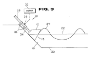
- Fig. 3 is an explanatory view illustrating still another embodiment of the wave making apparatus.
- a drive means comprises a drive shaft 34 connected to the wave generating plate 12, the drive shaft 34 having a rack 26 thereon.
- the drive means further comprises a pinion gear 28 engaged with the rack 26.
- a drive motor 35 is coupled to drive pinion gear 28, preferably through a reduction gearing (not shown).
- Mount 36 supports the drive shaft 34 and the drive motor 35 coupled to turn the pinion gear 28 for driving the wave generating plate 12 along a wall through the rack gear 26 on the drive shaft 34.
- the embodiment of Fig. 3 is similar to that of Fig. 1.
- FIG. 4 is a plan view illustrating the pool used in the surfing pool example of the invention.
- Fig. 5 is a cross-sectional view taken on the plane of line 2-2 of Fig. 4.
- the pool of Fig. 5 includes two wave making apparatuses 10a and 10b, which are the wave making apparatus 10 shown in Fig. 1.
- the distance from the bottom of pool 30 to the top surface of the water is indicated in parentheses.
- the bottom surface of pool 30 is lowest in the central area and slopes up toward the pool sides.
- a wave making apparatus was arranged at each end of two waterways 32a and 32b which are connected to pool 30.
- the waves generated by wave making apparatuses 10a and 10b pass through the two respective waterways 32a and 32b and cross each other in pool 30.
- high waves appropriate for surfing can be generated easily in pool 30, by means of the wave making apparatuses 10a and 10b.
- the form of wave 24 need not be sinusoidal. Waves 24 of high steepness ratio, which have peaked crests and flat troughs, are preferable.
- the drive unit for driving the wave generating plate 12 is not required to have a sophisticated sinusoidal motion control mechanism. A drive cycle range which cover a very limited range of the cycle is sufficient.
- the backward angle of inclination ⁇ of the wall 18 was at 45°, and the angle of inclination ⁇ of the wave generating face 13 of the wave generating plate 12 was set at 30°.
- the reciprocating cycle of operation of the wave generating plate was between 2 and 6 seconds.
- the design criteria for the stroke of the wave generating plate (distance of movement) for a given depth of water is as follows:
- the drive means for driving the wave generating plates can be freely chosen, to drive the wave generating plate 12, forward and backward (that is, "to and fro", substantially parallel to the surface of the rearwardly inclined surface 18 of the pool.
Landscapes
- Engineering & Computer Science (AREA)
- Architecture (AREA)
- Civil Engineering (AREA)
- Structural Engineering (AREA)
- Health & Medical Sciences (AREA)
- General Health & Medical Sciences (AREA)
- Physical Education & Sports Medicine (AREA)
- Structures Of Non-Positive Displacement Pumps (AREA)
- Other Liquid Machine Or Engine Such As Wave Power Use (AREA)
- Aerodynamic Tests, Hydrodynamic Tests, Wind Tunnels, And Water Tanks (AREA)
- Toys (AREA)
Description
- The present invention relates to a pool for surfing having two water ways connected to a wave pool having a wave making apparatus.
- FR-A-2 291 803 discloses a wave making apparatus comprising a wave generating plate having a wave generating face which is inclined for the center of a pool relativ to a stationary upper surface of the water in said pool. Furthermore, drive means in the form of a rod, a connecting rod and a rotating arm drive said generating plate along a wall which is upwardly and backwardly inclined relativ to the center of the wave pool.
- With the known wave making apparatus, however, it is not possible to generate waves which are suitable for surfing.
- It is therefore an object underlying the present invention to provide a pool having two water ways which comprises wave making apparatus being able to easily generate waves suitable for surfing.
- The solution of this object is achieved by the features of the main claim.
- As a result, high waves appropriate for surfing can be generated easily in a pool by means of two wave making apparatus units which are arranged at the end of two water ways of the pool which can be used as a surfing pool.
- The above objects and other objects and advantages of the present invention will become apparent from the detailed description to follow, taken in connection with the appended drawings.
- Fig. 1
- is an explanatory view illustrating a wave making apparatus for a pool according to the present invention;
- Fig. 2
- is an explanatory view illustrating another embodiment of a wave making apparatus for a pool according to the present invention;
- Fig. 3
- is an explanatory view illustrating still another embodiment of a wave making apparatus for a pool according to the present invention;
- Fig. 4
- is a plan view illustrating a pool for surfing according to the present invention; and
- Fig. 5
- is a cross-sectional view of the pool taken on the plane of line 2-2 of Fig. 4.
- A wave making apparatus of a pool for surfing comprises a wave generating plate which is driven along a pool wall so that waves cannot be generated behind the wave generating plate if high waves are generated. In this case, the pool wall, along which the wave generating plate slides, is inclined so that turbulence can be produced in a deeper zone of water.
- Fig. 1 is an explanatory view illustrating a
wave making apparatus 10 comprising awave generating plate 12 having a wave generating face 13 (front face of wave generating plate 12) which is inclined forward relative to the stationary upper surface of thewater 22 and means for drivingwave generating plate 12 alongwall 18,wall 18 being inclined backward relative to the center of the wave generating pool. The drive means forplate 12 has adrive shaft 14 coupled to thewave generating plate 12, amount 16 holding thedrive shaft 14, and a drive unit (not shown, but arranged in mount 16) drivingwave generating plate 12 alongwall 18 through thedrive shaft 14. To movewave generating plate 12 alongwall 18, driveshaft 14, coupled to thewave generating plate 12, and mount 16 holding thedrive shaft 14, are arranged so thatdrive shaft 14 andmount 16 have the same incline as that ofwall 18. - It is preferable to incline
wall 18 backward relative to the center of the wave pool at an angle α of 30° to 50° relative to the vertical plane. If thewall 18 is inclined at less than 30°, smaller turbulence is produced in a deeper zone of water. If the wall is inclined at more than 50°, thewave generating plate 12 will be required to be too large. - A minimum clearance between
wave generating plate 12 andwall 18 is sufficient to permit moving of thewave generating plate 12. If necessary, a slide guide can be provided betweenwave generating plate 12 andwall 18 in order to carry the partial weight or buoyancy ofwave generating plate 12. - The lower end of
wave generating plate 12 is positioned at a height abovepool bottom 20 which is equal to about one-half of the stroke or greater than the stroke necessary to generate waves of desired height. The upper end offront face 13 ofwave generating plate 12 is positioned at a height such that water does not splash over the top ofwave generating plate 12 when waves of desired height are generated.Wave generating face 13 ofwave generating plate 12 is inclined toward the center of the pool, i.e., inclined forward relative to the stationaryupper surface 22 of the water, to generate awave 24 moving toward the center of the pool. Thewave generating face 13 of thewave generating plate 12 is desired to be inclined toward the center of the pool at an angle β of 10° to 40° relative to the vertical plane. Thewave generating face 13 need not be flat; it may be curved, either convex or concave. The bottom face ofwave generating plate 12 is parallel toinclined wall 18. The top face ofwave generating plate 12 and the surface on which driveshaft 14 is mounted have no restriction on shape or orientation. In the embodiment of Fig. 1,wave generating plate 12 of a block shape having a rectangular section is used, but thewave generating plate 12 is not confined to the abovementioned shape. It is sufficient that thewave generating plate 12 has awave generating face 13 which is inclined forward. Awave generating plate 12 comprising a wave generating face, bottom face and an upper face and a wave generating plate of a shape of a thin plate having only a wave generating face can be used. - A drive means for
wave generating plate 12 comprisesdrive shaft 14 connected towave generating plate 12,mount 16 holding the drive shaft and a drive unit (not shown) for driving the wave generating plate alongwall 18 through said drive shaft. The drive unit coupled to driveshaft 14 may be hydraulic, pneumatic or electrical. The chain lines in Fig. 1 show thewave generating plate 12 in different positions, as driven by the drive means. - According to the wave making apparatus described above, when the
wave generating plate 12 is pushed into the water by being moved half a stroke downward alongwall 18 by the drive unit throughdrive shaft 14,wave generating face 13 ofwave generating plate 12 produces turbulence down to the deep zone in the water, thereby generating waves of desired height. Such generation of the waves by means ofwave generating plate 12 is carried out each timewave generating plate 12 is pushed into the water by being moved downward after being moved upward. Thus,wave 24 being generated continuously. - Fig. 2 is an explanatory view illustrating another embodiment of a wave making apparatus. The wave making apparatus of Fig. 2 comprises a hydraulic actuator which moves drive shaft 14' supported by mount 16'. A pneumatic actuator can be used as a drive unit in place of a hydraulic actuator. In other respects, the embodiment of Fig. 2 is the same as that of Fig. 1. A typical hydraulic drive unit is shown in Fig. 6, and is described below.
- Fig. 3 is an explanatory view illustrating still another embodiment of the wave making apparatus. In this embodiment, a drive means comprises a
drive shaft 34 connected to thewave generating plate 12, thedrive shaft 34 having arack 26 thereon. The drive means further comprises apinion gear 28 engaged with therack 26. Adrive motor 35 is coupled to drivepinion gear 28, preferably through a reduction gearing (not shown). Mount 36 supports thedrive shaft 34 and thedrive motor 35 coupled to turn thepinion gear 28 for driving thewave generating plate 12 along a wall through therack gear 26 on thedrive shaft 34. In other respects, the embodiment of Fig. 3 is similar to that of Fig. 1. - An example of the wave making apparatus arranged in a pool for surfing is shown in Figs. 4 and 5. Fig. 4 is a plan view illustrating the pool used in the surfing pool example of the invention. Fig. 5 is a cross-sectional view taken on the plane of line 2-2 of Fig. 4. The pool of Fig. 5 includes two
wave making apparatuses 10a and 10b, which are thewave making apparatus 10 shown in Fig. 1. In Fig. 4, the distance from the bottom ofpool 30 to the top surface of the water is indicated in parentheses. The bottom surface ofpool 30 is lowest in the central area and slopes up toward the pool sides. A wave making apparatus was arranged at each end of twowaterways pool 30. The waves generated bywave making apparatuses 10a and 10b pass through the tworespective waterways pool 30. As a result, high waves appropriate for surfing can be generated easily inpool 30, by means of thewave making apparatuses 10a and 10b. In the case of a wave making pool for surfing, the form ofwave 24 need not be sinusoidal.Waves 24 of high steepness ratio, which have peaked crests and flat troughs, are preferable. The drive unit for driving thewave generating plate 12 is not required to have a sophisticated sinusoidal motion control mechanism. A drive cycle range which cover a very limited range of the cycle is sufficient. - In a test example, the backward angle of inclination α of the
wall 18 was at 45°, and the angle of inclination β of thewave generating face 13 of thewave generating plate 12 was set at 30°. The reciprocating cycle of operation of the wave generating plate was between 2 and 6 seconds. The design criteria for the stroke of the wave generating plate (distance of movement) for a given depth of water is as follows:
- Consequently,

- The improved effects of the present invention are as follows:
- (a) The wave making apparatus can produce turbulence in a deep zone of water in comparison with prior art wave making apparatus. Therefore, high waves can be easily generated.
- (b) Any special wave absorbing work is not required because there is no surface of water behind the wave generating plate. Accordingly, the space around the wave making apparatus which is necessary for arranging said apparatus is reduced and, therefore, maneuverability for arranging the wave making apparatus increases.
- While the invention has been described above with respect to specific apparatus, it should be clear that various modifications and alternations can be made within the scope of the invention as defined in the appended claims. For example, the drive means for driving the wave generating plates can be freely chosen, to drive the
wave generating plate 12, forward and backward (that is, "to and fro", substantially parallel to the surface of the rearwardlyinclined surface 18 of the pool.
Claims (1)
- Pool for surfing having two water-ways (32a, 32b) connected to a wave pool (30) having a wave making apparatus comprising:
at least one wave generating plate (12) having a wave generating face (13) which is inclined toward the center of the wave pool (30) relative to a stationary upper surface (22) of water in said wave pool (30), and
drive means (14, 16; 14', 16'; 26, 28, 34, 35, 36) for driving said wave generating plate (12) along a wall (18) which is upwardly and backwardly inclined relative to the center of the wave pool (30),
said wave making apparatus comprising two wave making units (10a, 10b) being arranged at each end of the two water-ways (32a, 32b), the waves generated by said wave generating units (10a, 10b) passing through the two respective water-ways (32a, 32b) and crossing each other in said pool (30).
Applications Claiming Priority (2)
| Application Number | Priority Date | Filing Date | Title |
|---|---|---|---|
| JP134979/87 | 1987-06-01 | ||
| JP62134979A JPS63300783A (en) | 1987-06-01 | 1987-06-01 | Wave forming apparatus |
Publications (2)
| Publication Number | Publication Date |
|---|---|
| EP0293831A1 EP0293831A1 (en) | 1988-12-07 |
| EP0293831B1 true EP0293831B1 (en) | 1991-09-18 |
Family
ID=15141080
Family Applications (1)
| Application Number | Title | Priority Date | Filing Date |
|---|---|---|---|
| EP88108691A Expired - Lifetime EP0293831B1 (en) | 1987-06-01 | 1988-05-31 | Wave making apparatus |
Country Status (6)
| Country | Link |
|---|---|
| EP (1) | EP0293831B1 (en) |
| JP (1) | JPS63300783A (en) |
| KR (1) | KR920009136B1 (en) |
| AU (1) | AU597491B2 (en) |
| DE (1) | DE3864907D1 (en) |
| ES (1) | ES2025731T3 (en) |
Cited By (2)
| Publication number | Priority date | Publication date | Assignee | Title |
|---|---|---|---|---|
| WO2012150908A1 (en) * | 2011-05-04 | 2012-11-08 | Stagger Reef Pte. Ltd. | Method and apparatus for producing progressive waves suitable for surfing using staggered wave generators in sequence |
| US11534672B2 (en) | 2016-11-08 | 2022-12-27 | Ka'ana Wave Company Inc. | Wave producing method and apparatus |
Families Citing this family (16)
| Publication number | Priority date | Publication date | Assignee | Title |
|---|---|---|---|---|
| ATE145666T1 (en) * | 1992-08-14 | 1996-12-15 | Procter & Gamble | LIQUID DETERGENTS CONTAINING PEPTIDE TRIFLUOR METHYL KETONE |
| CA2393485C (en) * | 1999-12-13 | 2009-06-16 | Kerry Peter Black | Wave pool construction |
| DE10308812B4 (en) * | 2003-02-27 | 2007-05-16 | Bernd Reif | Device for generating standing waves in streams |
| AU2004240161B1 (en) | 2004-12-09 | 2006-04-13 | Liquid Time Ltd | Wave generating apparatus |
| DE102010035117B4 (en) * | 2010-08-23 | 2012-06-06 | Falko Müller | Plant and method for generating waves |
| KR101360275B1 (en) * | 2012-12-10 | 2014-02-12 | 윤대원 | Artificial wave generation device |
| AU2017251684B2 (en) * | 2017-02-09 | 2018-12-06 | Smartpark Technologies LLC | Surfing wave pool using ship waves |
| US10119284B1 (en) * | 2017-08-02 | 2018-11-06 | Ryan M. Dunlap | Wave generator |
| CN108221844B (en) * | 2017-12-31 | 2023-01-10 | 浙江大学 | Dynamic response test device for near-sea foundation pit under effect of simulated tidal load |
| FR3084266B1 (en) * | 2018-07-30 | 2020-10-16 | Laurent Hequily | DYNAMIC ARTIFICIAL WAVES INSTALLATION FOR THE PRACTICE OF SURFING |
| CN109342309B (en) * | 2018-11-26 | 2024-02-27 | 辽宁科技大学 | Test device and test method for simulating marine corrosion environment |
| CN110346112B (en) * | 2019-08-09 | 2024-01-26 | 交通运输部天津水运工程科学研究所 | Wave generator with adjustable wave generating width and convenient to assemble and disassemble |
| CN113295380B (en) * | 2021-06-08 | 2023-03-24 | 哈尔滨工程大学 | Wave making device |
| US11708700B2 (en) | 2021-08-18 | 2023-07-25 | Mark Bates | Wave generation assembly |
| CN115126305B (en) * | 2022-08-10 | 2024-05-14 | 浙江佳合文化科技股份有限公司 | Arc wave making device and wave making machine |
| CN117433743B (en) * | 2023-12-18 | 2024-02-13 | 天津大学 | Wave water tank for wave boundary layer experiment |
Family Cites Families (5)
| Publication number | Priority date | Publication date | Assignee | Title |
|---|---|---|---|---|
| US3005207A (en) * | 1959-01-13 | 1961-10-24 | Matrai Miklos | Swimming pool |
| US3350724A (en) * | 1964-07-07 | 1967-11-07 | Walter J Leigh | Method and apparatus for generating artificial waves in a body of water |
| FR2291803A1 (en) * | 1974-11-20 | 1976-06-18 | Alsthom Cgee | IMPROVEMENTS FOR SWELL GENERATORS OF THE DIVER TYPE |
| GB1592452A (en) * | 1976-04-20 | 1981-07-08 | Ind & Commercial Electronics L | Apparatus for creating waves in a body of liquid |
| DE3305508C2 (en) * | 1983-02-14 | 1984-12-20 | Christian Dr.-Ing. 1000 Berlin Boes | Pneumatic wave generator for surf wave pools |
-
1987
- 1987-06-01 JP JP62134979A patent/JPS63300783A/en active Granted
-
1988
- 1988-05-30 AU AU16761/88A patent/AU597491B2/en not_active Ceased
- 1988-05-31 EP EP88108691A patent/EP0293831B1/en not_active Expired - Lifetime
- 1988-05-31 ES ES198888108691T patent/ES2025731T3/en not_active Expired - Lifetime
- 1988-05-31 DE DE8888108691T patent/DE3864907D1/en not_active Expired - Fee Related
- 1988-06-01 KR KR1019880006594A patent/KR920009136B1/en not_active IP Right Cessation
Cited By (2)
| Publication number | Priority date | Publication date | Assignee | Title |
|---|---|---|---|---|
| WO2012150908A1 (en) * | 2011-05-04 | 2012-11-08 | Stagger Reef Pte. Ltd. | Method and apparatus for producing progressive waves suitable for surfing using staggered wave generators in sequence |
| US11534672B2 (en) | 2016-11-08 | 2022-12-27 | Ka'ana Wave Company Inc. | Wave producing method and apparatus |
Also Published As
| Publication number | Publication date |
|---|---|
| KR890000123A (en) | 1989-03-11 |
| JPH0512509B2 (en) | 1993-02-18 |
| DE3864907D1 (en) | 1991-10-24 |
| AU1676188A (en) | 1988-12-01 |
| AU597491B2 (en) | 1990-05-31 |
| EP0293831A1 (en) | 1988-12-07 |
| KR920009136B1 (en) | 1992-10-13 |
| ES2025731T3 (en) | 1992-04-01 |
| JPS63300783A (en) | 1988-12-07 |
Similar Documents
| Publication | Publication Date | Title |
|---|---|---|
| EP0293831B1 (en) | Wave making apparatus | |
| US3350724A (en) | Method and apparatus for generating artificial waves in a body of water | |
| US4062192A (en) | Method of and mechanism for generating waves suitable for surfing | |
| US3562823A (en) | Wave producing machine,especially for swimming pools | |
| US4098084A (en) | Apparatus for extracting energy from wave movement of the sea | |
| EP1681020B1 (en) | Ultrasonic imaging method and probe for 3D gynecologic inspection | |
| JP4845892B2 (en) | Wave generator | |
| EP3409337B1 (en) | Wave generator system with a barrier having lateral undulating movement for the generation of waves in two areas of water | |
| CN109946040B (en) | Liftable wave generation system | |
| US4235711A (en) | Means and method for sweeping material floating on water using vibrational energy | |
| US4048801A (en) | Process and device for harnessing wave energy | |
| CN113322914A (en) | Marine floater segmentation conveying collection ship | |
| RU2143371C1 (en) | Method of breaking ice cover | |
| JP2580337B2 (en) | Wave making tank | |
| ES2030326A6 (en) | Mechanism for converting a to-and-fro movement into a circular movement and obtaining energy from the waves | |
| CN219707300U (en) | Autonomous water craft utilizing wave energy | |
| SU983285A1 (en) | Continuous-action loading member | |
| JPS55140694A (en) | Propelling mechanism for ships | |
| CN113008511A (en) | Multi-plate swinging type wave making machine | |
| EP0390980B1 (en) | Device for obtaining energy from water | |
| JPH0617847B2 (en) | Wave making device | |
| RU93057397A (en) | METHOD FOR DRAWING SLAG FROM THE SURFACE OF THE METAL IN THE STEEL FILLING BUCKET AND DEVICE FOR ITS IMPLEMENTATION | |
| JPS5898517A (en) | Self-moving device in ship for performing curing process of soft ground | |
| JPH08150997A (en) | Oscillating hydrofoil type propulsion device for underwater robot | |
| SU766675A1 (en) | Apparatus for washing products |
Legal Events
| Date | Code | Title | Description |
|---|---|---|---|
| PUAI | Public reference made under article 153(3) epc to a published international application that has entered the european phase |
Free format text: ORIGINAL CODE: 0009012 |
|
| 17P | Request for examination filed |
Effective date: 19880531 |
|
| AK | Designated contracting states |
Kind code of ref document: A1 Designated state(s): DE ES FR GB IT |
|
| 17Q | First examination report despatched |
Effective date: 19900110 |
|
| GRAA | (expected) grant |
Free format text: ORIGINAL CODE: 0009210 |
|
| AK | Designated contracting states |
Kind code of ref document: B1 Designated state(s): DE ES FR GB IT |
|
| ITF | It: translation for a ep patent filed | ||
| REF | Corresponds to: |
Ref document number: 3864907 Country of ref document: DE Date of ref document: 19911024 |
|
| ET | Fr: translation filed | ||
| REG | Reference to a national code |
Ref country code: ES Ref legal event code: FG2A Ref document number: 2025731 Country of ref document: ES Kind code of ref document: T3 |
|
| PGFP | Annual fee paid to national office [announced via postgrant information from national office to epo] |
Ref country code: FR Payment date: 19920430 Year of fee payment: 5 |
|
| PGFP | Annual fee paid to national office [announced via postgrant information from national office to epo] |
Ref country code: ES Payment date: 19920514 Year of fee payment: 5 |
|
| PLBE | No opposition filed within time limit |
Free format text: ORIGINAL CODE: 0009261 |
|
| STAA | Information on the status of an ep patent application or granted ep patent |
Free format text: STATUS: NO OPPOSITION FILED WITHIN TIME LIMIT |
|
| 26N | No opposition filed | ||
| PG25 | Lapsed in a contracting state [announced via postgrant information from national office to epo] |
Ref country code: ES Free format text: LAPSE BECAUSE OF NON-PAYMENT OF DUE FEES Effective date: 19930601 |
|
| PG25 | Lapsed in a contracting state [announced via postgrant information from national office to epo] |
Ref country code: FR Effective date: 19940131 |
|
| REG | Reference to a national code |
Ref country code: FR Ref legal event code: ST |
|
| PGFP | Annual fee paid to national office [announced via postgrant information from national office to epo] |
Ref country code: GB Payment date: 19980522 Year of fee payment: 11 |
|
| PGFP | Annual fee paid to national office [announced via postgrant information from national office to epo] |
Ref country code: DE Payment date: 19980608 Year of fee payment: 11 |
|
| REG | Reference to a national code |
Ref country code: ES Ref legal event code: FD2A Effective date: 19990301 |
|
| PG25 | Lapsed in a contracting state [announced via postgrant information from national office to epo] |
Ref country code: GB Free format text: LAPSE BECAUSE OF NON-PAYMENT OF DUE FEES Effective date: 19990531 |
|
| GBPC | Gb: european patent ceased through non-payment of renewal fee |
Effective date: 19990531 |
|
| PG25 | Lapsed in a contracting state [announced via postgrant information from national office to epo] |
Ref country code: DE Free format text: LAPSE BECAUSE OF NON-PAYMENT OF DUE FEES Effective date: 20000301 |
|
| PG25 | Lapsed in a contracting state [announced via postgrant information from national office to epo] |
Ref country code: IT Free format text: LAPSE BECAUSE OF NON-PAYMENT OF DUE FEES;WARNING: LAPSES OF ITALIAN PATENTS WITH EFFECTIVE DATE BEFORE 2007 MAY HAVE OCCURRED AT ANY TIME BEFORE 2007. THE CORRECT EFFECTIVE DATE MAY BE DIFFERENT FROM THE ONE RECORDED. Effective date: 20050531 |