EP0293167B1 - A communications jammer - Google Patents
A communications jammer Download PDFInfo
- Publication number
- EP0293167B1 EP0293167B1 EP88304686A EP88304686A EP0293167B1 EP 0293167 B1 EP0293167 B1 EP 0293167B1 EP 88304686 A EP88304686 A EP 88304686A EP 88304686 A EP88304686 A EP 88304686A EP 0293167 B1 EP0293167 B1 EP 0293167B1
- Authority
- EP
- European Patent Office
- Prior art keywords
- local
- transmission
- frequency
- jammer
- jamming signal
- Prior art date
- Legal status (The legal status is an assumption and is not a legal conclusion. Google has not performed a legal analysis and makes no representation as to the accuracy of the status listed.)
- Expired - Lifetime
Links
Images

Classifications
-
- H—ELECTRICITY
- H04—ELECTRIC COMMUNICATION TECHNIQUE
- H04K—SECRET COMMUNICATION; JAMMING OF COMMUNICATION
- H04K3/00—Jamming of communication; Counter-measures
- H04K3/40—Jamming having variable characteristics
- H04K3/45—Jamming having variable characteristics characterized by including monitoring of the target or target signal, e.g. in reactive jammers or follower jammers for example by means of an alternation of jamming phases and monitoring phases, called "look-through mode"
-
- H—ELECTRICITY
- H04—ELECTRIC COMMUNICATION TECHNIQUE
- H04K—SECRET COMMUNICATION; JAMMING OF COMMUNICATION
- H04K3/00—Jamming of communication; Counter-measures
- H04K3/40—Jamming having variable characteristics
- H04K3/41—Jamming having variable characteristics characterized by the control of the jamming activation or deactivation time
-
- H—ELECTRICITY
- H04—ELECTRIC COMMUNICATION TECHNIQUE
- H04K—SECRET COMMUNICATION; JAMMING OF COMMUNICATION
- H04K3/00—Jamming of communication; Counter-measures
- H04K3/40—Jamming having variable characteristics
- H04K3/42—Jamming having variable characteristics characterized by the control of the jamming frequency or wavelength
Definitions
- the present invention relates to methods of, and apparatus for jamming radio communication systems and in particular to what are known as "leave-behind jammers".
- Such devices are designed for military use, being left during strategic withdrawal from an area so that after the area is over-run by hostile forces the jammers disrupt communications systems in the vicinity.
- To be effective many such jammers need to be deployed in order to cover the many transmissions likely in a complex communications system and to provide sufficient redundancy for jamming still to be effective even after a proportion of the jammers have been detected and disabled.
- the jammers should be rugged, portable and sufficiently inexpensive to be regarded as expendable.
- jamming fall broadly into two categories: “smart set-on” and “barrage”.
- the jamming device is designed to detect a tranmission from a station local to the jamming device and to transmit a high power jamming signal concurrently with the local transmission.
- the jammer transmits jamming signals continuously over a wide band to jam any reception by a local receiving station. Both these methods require the use of high power outputs and since leave-behind jammers must necessarily contain their own power supplies these high power requirements have been a major obstacle to the achievement of reductions in size and cost. It is known to have a jammer of the former type, i.e.
- a "smart set-on device” comprising receiving means for receiving a local radio transmission, frequency determining means for determining the frequency of the local radio transmission, and jamming signal transmitting means for transmitting a jamming signal at a frequency controlled in accordance with the frequency determined by the frequency determining means at a time subsequent to the reception of the local radio transmission by the receiving means.
- British patents nos. 1,278,771 and 1,450,761 disclose examples of such jammers designed to jam radio transmissions in which short messages of typically one tenth of a second duration are transmitted. The jammer is designed to transmit a jamming signal concurrently with the detected transmission.
- the jammer has to switch rapidly between searching for transmissions and the transmission of a jamming signal in a time-scale of a few milliseconds in order to jam effectively the detected short duration signal before it ceases.
- This jammer requires sophisticated circuitry in both its detection and jamming stages in order to function at the high speeds required.
- United States patent no. 4,214,208 discloses a further example of such a jammer.
- the jammer disclosed in this patent transmits a jamming signal concurrently with the victim signal.
- the victim signal is a keyed continuous wave signal of the type used in radio telegraphy
- the jamming signal is also keyed, having a complementary waveform with each pulse timed to follow immediately upon an individual corresponding pulse of the victim signal.
- the jamming signal has to be of substantially the same power level as the victim signal in order to be effective.
- such a jammer is characterised in that the receiving means include monitoring means arranged to detect the end of the local radio transmission and to trigger the operation of the jammer signal transmitting means only after the end of the local radio transmission and in that the jamming signal transmitting means are arranged to transmit a low power signal for a period of time after the end of the local radio transmission so that the jammer jams local reception of a response of a non-local station to the local radio transmission.
- the present invention takes advantage of some of the typical characteristics of radio communications nets to provide a jammer which while wholly effective against such nets requires far less power than known jamming devices.
- This method of jamming used is effective against communication nets because the messages occur not individually but consecutively in groups on the same frequency.
- a transmission by a local station to a distant station is immediately followed by a transmission from the distant station back to the local station.
- the present invention allows the use of a relatively simple low sensitivity receiver which responds only to transmissions at the high power level characteristic of a communications station in its immediate vicinity.
- the jamming receiver has a considerable range advantage over the distant transmitting station.
- the efficiency of power use is further increased by transmitting jamming signals only at the one frequency of the detected transmission rather than over an entire band.
- the jamming device Since messages transmitted in a typical communications net last only a few seconds and even the longer ones contain critical information in the first few seconds it is necessary for the jamming device to transmit a jamming signal for only a few seconds at a time. Moreover since the jamming transceiver does not have to respond instantly to the detection of a hostile transmission but only after the cessation of the hostile transmission the present invention allows the use in the jamming device of a simple and inexpensive scanning receiver without the relatively slow search/response time of such a receiver compromising the overall performance of the device.
- a jamming transceiver in accordance with the present invention allows it to be built at relatively low cost and hence to be deployed in large numbers.
- As a result of the low power requirements such a jamming transceiver can be relatively compact despite the need to include an internal power source.
- a useful operational duration in excess of twentyfour hours can be achieved from a power supply of compact and lightweight batteries.
- the monitoring means include logic circuits arranged to analyse the received local radio transmission to discriminate between hostile and non-hostile transmissions and to control the frequency determining means to stop monitoring at the frequency of non-hostile transmissions.
- the jamming signal transmitting means include means for imposing an identification code on the jamming signal.
- the jammer includes a local frequency oscillator common to the receiving means and the jamming signal transmitting means and a switch arranged to connect the local frequency oscillator to other components of the transmitting means when the jammer is in a transmitting mode and to other components of the receiving means when the jammer is in a receiving mode.
- the local frequency oscillator is a fast-settling frequency synthesiser arranged when the jammer is in the receiving mode to scan incrementally through a range of frequencies until a local radio transmission is detected.
- a method of operating a jammer to disrupt radio communications comprising detecting a hostile local transmission, determining the frequency of the local transmission, subsequently transmitting a jamming signal at a frequency controlled in accordance with the determined frequency, and ceasing transmission of the jamming signal until a further local transmission is detected is characterised in that the jamming signal is transmitted only after the cessation of the local transmission to jam the local reception of a response of a non-local station to the local transmission.
- a jamming device in accordance with the present invention comprises a transceiver 1 and a battery 2.
- the transceiver 1 and the battery 2 are each contained within cast alloy cases, these cases being held together by clips 3 to provide a single compact unit which may be lifted by a fixed handle 4.
- An antenna 5, a switch 6 and a delay timer 7 are provided on an upper surface of the case holding the transceiver 1.
- the operation of the transceiver is initiated by the switch 6. Detection and jamming of hostile signals may then start immediately or alternatively after the expiry of a predetermined period set on the delay timer 7.
- the transceiver 1 is in a receive (RX) mode. In this mode the transceiver 1 scans through a range of frequencies until a signal at a level sufficiently high to be that of a local transmission is detected. This signal is then analysed. If the signal is determined to be non-hostile, such as a transmission from another jamming device encoded with an appropriate identification signal, then the transceiver remains in the RX mode and continues to scan for hostile transmissions.
- the transceiver 1 Equally if the signal is found to have the characteristics of an anti-jamming decoy beacon the transceiver 1 remains in the RX mode. If however the analysis identifies the signal as being hostile then the transceiver 1 remains locked onto the frequency of the hostile signal. After the hostile transmission ceases the transceiver 1 switches to a transmission (TX) mode in which a jamming signal encoded with an appropriate identification code is transmitted for a predetermined period typically of 2 to 3 seconds duration. The transmission may start immediately after the cessation of the hostile transmission or alternatively following a predetermined delay, according to the known characteristics of the communications net being jammed.
- TX transmission
- the transceiver After transmitting the jamming signal for the predetermined period the transceiver returns to the RX mode until a further local hostile transmission is detected.
- the power consumption of a jamming device using this method of operation is exceptionally low. Effective jamming can be achieved using output powers less than 50 Watts and typically in a range as low as 1-10 Watts.
- the battery 3 is of the 12 volt 10 Ampere-hour Manganese-alkaline type. As a result of the low power requirements such a battery can power continuous operation of the jamming device for over twentyfour hours.
- the combined weight of a battery together with the transceiver 1 is typically little more than 1 Kg and the jamming device as a whole may have a volume of less than two litres.
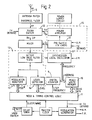
- the design of the transceiver is shown schematically in Figure 2.
- the receiving stages of the transceiver 1 are formed by a homodyne receiver in which the local oscillator (LO) signal is supplied by a fast-settling frequency synthesiser 8 when the transceiver is in the RX mode. Since receive and transmit periods do not overlap this same local oscillator 8 is also used to provide the jamming waveform (with suitable modulation AM or FM imposed) when the transceiver is in the TX mode. This use of a single oscillator considerably simplifies construction.
- a simple RX/TX switch 12 serves to connect the power amplifier in the circuit in the TX mode.
- IF filter As the intermediate frequency (IF) is zero in a homodyne receiver the usual IF filter is replaced by an active low-pass filter operating at audio frequencies (AF). As this filter needs no inductive or crystal components it is put with the rest of the signal circuitry on a chip-carrier or hybrid circuit to aid miniaturisation.
- AF audio frequencies
- the synthesiser frequency is controlled digitally by the output of a digital counter 9 which also feeds the address lines of a read/write memory 10. This allows each frequency to be checked against a preprogrammed list of those frequencies known to be associated with hostile transmissions while that frequency is being received. This preprogrammed list may be updated during the operation of the jamming device if required. If the frequency is associated with non-hostile transmissions, or if no signal appears above the detector threshhold, the counter 9 may be stepped onto the next frequency. If a signal is detected control logic circuits 11 can time its duration and decide whether to jam when its stops or alternatively to ignore it or to move on to the next frequency.
- the jamming logic may be integrated on a gate-array or alternatively implemented by software in a microprocessor.
Description
- The present invention relates to methods of, and apparatus for jamming radio communication systems and in particular to what are known as "leave-behind jammers". Such devices are designed for military use, being left during strategic withdrawal from an area so that after the area is over-run by hostile forces the jammers disrupt communications systems in the vicinity. To be effective many such jammers need to be deployed in order to cover the many transmissions likely in a complex communications system and to provide sufficient redundancy for jamming still to be effective even after a proportion of the jammers have been detected and disabled. Ideally therefore the jammers should be rugged, portable and sufficiently inexpensive to be regarded as expendable.
- Known methods of jamming fall broadly into two categories: "smart set-on" and "barrage". In the former the jamming device is designed to detect a tranmission from a station local to the jamming device and to transmit a high power jamming signal concurrently with the local transmission. In the latter method the jammer transmits jamming signals continuously over a wide band to jam any reception by a local receiving station. Both these methods require the use of high power outputs and since leave-behind jammers must necessarily contain their own power supplies these high power requirements have been a major obstacle to the achievement of reductions in size and cost. It is known to have a jammer of the former type, i.e. a "smart set-on device" comprising receiving means for receiving a local radio transmission, frequency determining means for determining the frequency of the local radio transmission, and jamming signal transmitting means for transmitting a jamming signal at a frequency controlled in accordance with the frequency determined by the frequency determining means at a time subsequent to the reception of the local radio transmission by the receiving means. British patents nos. 1,278,771 and 1,450,761 disclose examples of such jammers designed to jam radio transmissions in which short messages of typically one tenth of a second duration are transmitted. The jammer is designed to transmit a jamming signal concurrently with the detected transmission. The jammer has to switch rapidly between searching for transmissions and the transmission of a jamming signal in a time-scale of a few milliseconds in order to jam effectively the detected short duration signal before it ceases. This jammer requires sophisticated circuitry in both its detection and jamming stages in order to function at the high speeds required.
- United States patent no. 4,214,208 discloses a further example of such a jammer. In common with other known jamming devices the jammer disclosed in this patent transmits a jamming signal concurrently with the victim signal. In this case because the victim signal is a keyed continuous wave signal of the type used in radio telegraphy the jamming signal is also keyed, having a complementary waveform with each pulse timed to follow immediately upon an individual corresponding pulse of the victim signal. As with the other devices discussed above the jamming signal has to be of substantially the same power level as the victim signal in order to be effective.
- According to the present invention such a jammer is characterised in that the receiving means include monitoring means arranged to detect the end of the local radio transmission and to trigger the operation of the jammer signal transmitting means only after the end of the local radio transmission and in that the jamming signal transmitting means are arranged to transmit a low power signal for a period of time after the end of the local radio transmission so that the jammer jams local reception of a response of a non-local station to the local radio transmission.
- The present invention takes advantage of some of the typical characteristics of radio communications nets to provide a jammer which while wholly effective against such nets requires far less power than known jamming devices. This method of jamming used is effective against communication nets because the messages occur not individually but consecutively in groups on the same frequency. Thus typically a transmission by a local station to a distant station is immediately followed by a transmission from the distant station back to the local station. By relying upon detection of the first step in this process, that is transmission by a local station, the present invention allows the use of a relatively simple low sensitivity receiver which responds only to transmissions at the high power level characteristic of a communications station in its immediate vicinity. However since jamming is carried out not during the transmission by the local station but subsequently during transmission from a distant station to the local station effective jamming can be achieved using low power levels: the jamming receiver has a considerable range advantage over the distant transmitting station. The efficiency of power use is further increased by transmitting jamming signals only at the one frequency of the detected transmission rather than over an entire band.
- Since messages transmitted in a typical communications net last only a few seconds and even the longer ones contain critical information in the first few seconds it is necessary for the jamming device to transmit a jamming signal for only a few seconds at a time. Moreover since the jamming transceiver does not have to respond instantly to the detection of a hostile transmission but only after the cessation of the hostile transmission the present invention allows the use in the jamming device of a simple and inexpensive scanning receiver without the relatively slow search/response time of such a receiver compromising the overall performance of the device.
- The simplicity and the low power requirements of a jamming transceiver in accordance with the present invention allows it to be built at relatively low cost and hence to be deployed in large numbers. As a result of the low power requirements such a jamming transceiver can be relatively compact despite the need to include an internal power source. A useful operational duration in excess of twentyfour hours can be achieved from a power supply of compact and lightweight batteries.
- Preferably the monitoring means include logic circuits arranged to analyse the received local radio transmission to discriminate between hostile and non-hostile transmissions and to control the frequency determining means to stop monitoring at the frequency of non-hostile transmissions.
- Preferably the jamming signal transmitting means include means for imposing an identification code on the jamming signal.
- Preferably the jammer includes a local frequency oscillator common to the receiving means and the jamming signal transmitting means and a switch arranged to connect the local frequency oscillator to other components of the transmitting means when the jammer is in a transmitting mode and to other components of the receiving means when the jammer is in a receiving mode.
- Preferably the local frequency oscillator is a fast-settling frequency synthesiser arranged when the jammer is in the receiving mode to scan incrementally through a range of frequencies until a local radio transmission is detected.
- According to a second aspect of this invention a method of operating a jammer to disrupt radio communications comprising detecting a hostile local transmission, determining the frequency of the local transmission, subsequently transmitting a jamming signal at a frequency controlled in accordance with the determined frequency, and ceasing transmission of the jamming signal until a further local transmission is detected is characterised in that the jamming signal is transmitted only after the cessation of the local transmission to jam the local reception of a response of a non-local station to the local transmission.
- A method and device in accordance with the present invention are now described in detail with reference to the accompanying drawings in which:-
- Figure 1 is a side elevation of a jamming device in accordance with the present invention; and,
- Figure 2 is a block diagram of such a device.
- A jamming device in accordance with the present invention comprises a transceiver 1 and a
battery 2. The transceiver 1 and thebattery 2 are each contained within cast alloy cases, these cases being held together by clips 3 to provide a single compact unit which may be lifted by a fixed handle 4. Anantenna 5, a switch 6 and a delay timer 7 are provided on an upper surface of the case holding the transceiver 1. - In use the operation of the transceiver is initiated by the switch 6. Detection and jamming of hostile signals may then start immediately or alternatively after the expiry of a predetermined period set on the delay timer 7. Initially the transceiver 1 is in a receive (RX) mode. In this mode the transceiver 1 scans through a range of frequencies until a signal at a level sufficiently high to be that of a local transmission is detected. This signal is then analysed. If the signal is determined to be non-hostile, such as a transmission from another jamming device encoded with an appropriate identification signal, then the transceiver remains in the RX mode and continues to scan for hostile transmissions. Equally if the signal is found to have the characteristics of an anti-jamming decoy beacon the transceiver 1 remains in the RX mode. If however the analysis identifies the signal as being hostile then the transceiver 1 remains locked onto the frequency of the hostile signal. After the hostile transmission ceases the transceiver 1 switches to a transmission (TX) mode in which a jamming signal encoded with an appropriate identification code is transmitted for a predetermined period typically of 2 to 3 seconds duration. The transmission may start immediately after the cessation of the hostile transmission or alternatively following a predetermined delay, according to the known characteristics of the communications net being jammed.
- In general transmission and reception by the stations of a communications net take place at a single frequency. In this case to jam reception of transmission from a distant station by a local station it is sufficient for the jamming device to transmit a jamming signal at the same frequency as the detected local transmission. If however the communications net is of the type using duplex operation with a predetermined frequency offset between received and transmitted signals then the transceiver is preprogrammed to transmit the jamming signal at a frequency separated from the frequency of the detected local transmission by a corresponding offset.
- After transmitting the jamming signal for the predetermined period the transceiver returns to the RX mode until a further local hostile transmission is detected.
- Because of the low power required to jam local reception of transmission by a distant station the power consumption of a jamming device using this method of operation is exceptionally low. Effective jamming can be achieved using output powers less than 50 Watts and typically in a range as low as 1-10 Watts. Typically the battery 3 is of the 12
volt 10 Ampere-hour Manganese-alkaline type. As a result of the low power requirements such a battery can power continuous operation of the jamming device for over twentyfour hours. The combined weight of a battery together with the transceiver 1 is typically little more than 1 Kg and the jamming device as a whole may have a volume of less than two litres. - The design of the transceiver is shown schematically in Figure 2. The receiving stages of the transceiver 1 are formed by a homodyne receiver in which the local oscillator (LO) signal is supplied by a fast-settling frequency synthesiser 8 when the transceiver is in the RX mode. Since receive and transmit periods do not overlap this same local oscillator 8 is also used to provide the jamming waveform (with suitable modulation AM or FM imposed) when the transceiver is in the TX mode. This use of a single oscillator considerably simplifies construction. A simple RX/
TX switch 12 serves to connect the power amplifier in the circuit in the TX mode. - As the intermediate frequency (IF) is zero in a homodyne receiver the usual IF filter is replaced by an active low-pass filter operating at audio frequencies (AF). As this filter needs no inductive or crystal components it is put with the rest of the signal circuitry on a chip-carrier or hybrid circuit to aid miniaturisation.
- The synthesiser frequency is controlled digitally by the output of a
digital counter 9 which also feeds the address lines of a read/write memory 10. This allows each frequency to be checked against a preprogrammed list of those frequencies known to be associated with hostile transmissions while that frequency is being received. This preprogrammed list may be updated during the operation of the jamming device if required. If the frequency is associated with non-hostile transmissions, or if no signal appears above the detector threshhold, thecounter 9 may be stepped onto the next frequency. If a signal is detectedcontrol logic circuits 11 can time its duration and decide whether to jam when its stops or alternatively to ignore it or to move on to the next frequency. - The jamming logic may be integrated on a gate-array or alternatively implemented by software in a microprocessor.
Claims (9)
- A jammer comprising receiving means (5, 13) for receiving a local radio transmission, frequency determining means (8, 9, 10, 11) for determining the frequency of the local radio transmission, and jamming signal transmitting means (5, 14) for transmitting a jamming signal at a frequency controlled in accordance with the frequency determined by the frequency determining means (8, 9, 10, 11) at a time subsequent to the reception of the local radio transmission by the receiving means, characterised in that the receiving means include monitoring means (11, 15, 16) arranged to detect the end of the local radio transmission and to trigger the operation of the jamming signal transmitting means (5, 14) only after the end of the local radio transmission and in that the jamming signal transmitting means (5, 14) are arranged to transmit a low power signal for a period of time after the end of the local radio transmission so that the jammer jams local reception of a response of a non-local station to the local radio transmission.
- A jammer according to Claim 1, in which the monitoring means (11, 15, 16) include logic circuits (11) arranged to analyse the received local radio transmission to discriminate between hostile and non-hostile transmissions and to control the frequency determining means to stop monitoring at the frequency of non-hostile transmissions.
- A jammer according to Claim 2, in which the jamming signal transmitting means (5, 14) include means (17) for imposing an identification code on the jamming signal.
- A jammer according to any one of the preceding Claims, in which the jammer includes a local frequency oscillator (8) common to the receiving means (5, 13) and the jamming signal transmitting means (5, 14) and a switch (12) arranged to connect the local frequency oscillator (8) to other components of the transmitting means (5, 14) when the jammer is in a transmitting mode and to other components of the receiving means (5, 13) when the jammer is in a receiving mode.
- A jammer according to Claim 4, in which the local frequency oscillator (8) is a fast-settling frequency synthesiser arranged when the jammer is in the receiving mode to scan through a range of frequencies until a local radio transmission is detected.
- A method of operating a jammer to disrupt radio communications comprising detecting a hostile local transmission, determining the frequency of the local transmission, subsequently transmitting a jamming signal at a frequency controlled in accordance with the determined frequency, and ceasing transmission of the jamming signal until a further local transmission is detected characterised in that the jamming signal is transmitted only after the cessation of the local transmission to jam the local reception of a response of a non-local station to the local transmission.
- A method according to claim 6, further comprising analysing the local transmission to discriminate between hostile and non-hostile transmissions and ceasing monitoring of any transmission determined to be non-hostile.
- A method according to claim 6 or 7, further comprising imposing an identification on the jamming signal.
- A method according to claim 8 when dependent on claim 7, in which the step of analysing the local transmission includes determining whether the local transmission includes a signal identifying the local transmission as non-hostile.
Applications Claiming Priority (2)
| Application Number | Priority Date | Filing Date | Title |
|---|---|---|---|
| GB878712393A GB8712393D0 (en) | 1987-05-27 | 1987-05-27 | Communications jammer |
| GB8712393 | 1987-05-27 |
Publications (3)
| Publication Number | Publication Date |
|---|---|
| EP0293167A2 EP0293167A2 (en) | 1988-11-30 |
| EP0293167A3 EP0293167A3 (en) | 1990-01-24 |
| EP0293167B1 true EP0293167B1 (en) | 1992-11-25 |
Family
ID=10617949
Family Applications (1)
| Application Number | Title | Priority Date | Filing Date |
|---|---|---|---|
| EP88304686A Expired - Lifetime EP0293167B1 (en) | 1987-05-27 | 1988-05-24 | A communications jammer |
Country Status (6)
| Country | Link |
|---|---|
| US (1) | US5001771A (en) |
| EP (1) | EP0293167B1 (en) |
| CA (1) | CA1297160C (en) |
| DE (1) | DE3876142T2 (en) |
| GB (1) | GB8712393D0 (en) |
| NO (1) | NO170659C (en) |
Cited By (1)
| Publication number | Priority date | Publication date | Assignee | Title |
|---|---|---|---|---|
| RU2494531C1 (en) * | 2012-04-12 | 2013-09-27 | Федеральное государственное казенное военное образовательное учреждение высшего профессионального образования "ВОЕННАЯ АКАДЕМИЯ СВЯЗИ имени Маршала Советского Союза С.М. Буденного" Министерства обороны Российской Федерации | Method for radio jamming of communication channels |
Families Citing this family (41)
| Publication number | Priority date | Publication date | Assignee | Title |
|---|---|---|---|---|
| GB8712393D0 (en) * | 1987-05-27 | 1988-06-02 | British Aerospace | Communications jammer |
| JP2821198B2 (en) * | 1989-10-02 | 1998-11-05 | キヤノン株式会社 | Frequency processing circuit |
| US5313209A (en) * | 1993-11-12 | 1994-05-17 | The United States Of America As Represented By The Secretary Of The Army | Sweep jammer identification process |
| US5673049A (en) * | 1996-01-26 | 1997-09-30 | Kitchen; William J. | Police radar jammer |
| IL119694A0 (en) * | 1996-11-26 | 1997-06-10 | Point Ltd V | A method and device to disable cellular communication |
| US6112052A (en) * | 1997-01-29 | 2000-08-29 | Northrop Grumman Corporation | Remote controlled noise jamming device |
| FR2764144B1 (en) * | 1997-06-02 | 2000-06-02 | Raoul Girod | APPARATUS FOR FILTERING RADIOTELEPHONES |
| ES2138557B1 (en) * | 1998-02-26 | 2000-08-16 | Carballo Jose Maria Pousada | CALL MASKER FOR MOBILE TELEPHONY. |
| US6195529B1 (en) * | 1998-03-12 | 2001-02-27 | Joachim Linz | Transmission blocker for mobile radio stations and method for preventing transmission activities of a mobile radio station |
| US7263367B1 (en) * | 1999-04-28 | 2007-08-28 | Sabot Associates, Inc. | Systems and methods for setting a mode of operation of electronic devices |
| US7653385B2 (en) * | 2001-01-26 | 2010-01-26 | Arend Brian L | Wireless telecommunications signal inhibition |
| KR20020072664A (en) * | 2001-03-12 | 2002-09-18 | 엘지이노텍 주식회사 | Circuit for generating jamming signal of jamming response device |
| US7123874B1 (en) | 2001-12-10 | 2006-10-17 | Joseph P Brennan | Cellular phone blocker |
| US7050755B2 (en) * | 2002-01-24 | 2006-05-23 | Pctel Maryland, Inc. | Targeted mobile terminal communication blocker |
| CA2475794A1 (en) * | 2003-08-21 | 2005-02-21 | Geoffrey Lawrence Alford | Method and apparatus for providing an electronic warfare target simulator |
| US7728755B1 (en) | 2005-03-16 | 2010-06-01 | Damjan Jocic | Reactive parallel processing jamming system |
| US8767595B2 (en) * | 2005-08-02 | 2014-07-01 | L-3 Communications Corporation | Enhanced methods of cellular environment detection when interoperating with timed interfers |
| WO2007016641A2 (en) * | 2005-08-02 | 2007-02-08 | Comhouse Wireless, Lp | Methods of remotely identifying, suppressing and/or disabling wireless devices of interest |
| KR20080086876A (en) * | 2005-12-07 | 2008-09-26 | 시에라 네바다 코포레이션 | Communications and data link jammer incorporating fiber-optic delay line technology |
| US8140001B2 (en) | 2006-03-07 | 2012-03-20 | L-3 Communications Corporation | Methods of suppressing GSM wireless device threats in dynamic or wide area static environments using minimal power and collateral interference |
| US8755770B2 (en) * | 2006-08-01 | 2014-06-17 | L-3 Communications Corporation | Methods for identifying wireless devices connected to potentially threatening devices |
| US20100226308A1 (en) * | 2006-08-15 | 2010-09-09 | Comhouse Wireless Lp | node- arbitrated media access control protocol for ad hoc broadcast networks carrying ephemeral information |
| US20090215387A1 (en) * | 2008-01-16 | 2009-08-27 | Brennan Joseph P | In-vehicle cellular device blocker to restrict cellular use for operator |
| US20110065456A1 (en) * | 2009-04-20 | 2011-03-17 | Brennan Joseph P | Cellular device deactivation system |
| US8477727B2 (en) * | 2009-07-29 | 2013-07-02 | L-3 Communications Corporation | Methods for surreptitious manipulation of CDMA 2000 wireless devices |
| US8526395B2 (en) * | 2009-09-04 | 2013-09-03 | L-3 Communications Corporation | Using code channel overrides to suppress CDMA wireless devices |
| RU2443058C2 (en) * | 2010-04-05 | 2012-02-20 | Федеральное Государственное Унитарное Предприятие "Научно-Исследовательский Институт "Экран" | Method for coherent interference formation |
| RU2450458C1 (en) * | 2011-04-13 | 2012-05-10 | Федеральное государственное военное образовательное учреждение высшего профессионального образования "Военная академия связи имени маршала Советского Союза С.М. Буденного" Министерства Обороны Российской Федерации (Минобороны России) | Method of radio suppression of communication channels |
| RU2541931C1 (en) * | 2014-03-21 | 2015-02-20 | Юрий Пантелеевич Лепеха | Apparatus for protecting computers and components thereof from unauthorised activity |
| US10020909B2 (en) | 2015-09-23 | 2018-07-10 | Battelle Memorial Institute | Dual-grip portable countermeasure device against unmanned systems |
| KR102407878B1 (en) | 2015-09-23 | 2022-06-17 | 바텔리 메모리얼 인스티튜트 | Portable countermeasure device against unmanned systems |
| US10574384B2 (en) | 2015-09-23 | 2020-02-25 | Dedrone Holdings, Inc. | Dual-grip portable countermeasure device against unmanned systems |
| RU2622631C1 (en) * | 2016-03-11 | 2017-06-16 | Федеральное государственное казенное военное образовательное учреждение высшего образования "Академия Федеральной службы охраны Российской Федерации" (Академия ФСО России) | Method of forming masking interference for protection of speech information |
| USD872820S1 (en) | 2016-09-23 | 2020-01-14 | Dedrone Holdings, Inc. | Dual-grip portable countermeasure device against unmanned systems |
| US9787425B1 (en) | 2017-01-11 | 2017-10-10 | Carlos M Gonzalez | Device and method for jamming over the air signals in a geographical delimited area |
| RU2677261C1 (en) * | 2017-10-06 | 2019-01-16 | федеральное государственное казенное военное образовательное учреждение высшего образования "Военная академия связи имени Маршала Советского Союза С.М. Буденного" Министерства обороны Российской Федерации | Satellite control channels radio suppression method |
| USD872819S1 (en) | 2018-03-28 | 2020-01-14 | Dedrone Holdings, Inc. | Portable countermeasure device against unmanned systems |
| EP3697004A3 (en) * | 2019-02-15 | 2020-12-02 | Tata Consultancy Services Limited | System, method and machine-readable storage medium for disrupting unauthorized communications in low frequency radio communication devices |
| RU2762378C2 (en) * | 2020-02-07 | 2021-12-20 | Тимофей Андреевич Семенюк | Apparatus for blocking radio-controlled explosive apparatuses |
| RU2754110C1 (en) * | 2020-11-06 | 2021-08-26 | федеральное государственное казенное военное образовательное учреждение высшего образования "Военная академия связи имени Маршала Советского Союза С.М. Буденного" Министерства обороны Российской Федерации | Method for radio jamming of satellite control channels |
| RU2755489C1 (en) * | 2021-02-03 | 2021-09-16 | Федеральное государственное образовательное учреждение высшего образования "Владимирский государственный университет имени Александра Григорьевича и Николая Григорьевича Столетовых" (ВлГУ) | Radio-controlled apparatus blocker |
Family Cites Families (12)
| Publication number | Priority date | Publication date | Assignee | Title |
|---|---|---|---|---|
| US4264909A (en) * | 1957-09-05 | 1981-04-28 | Rockwell International Corporation | Frequency searching and/or jamming means |
| DE978041C (en) * | 1960-09-22 | 1976-10-21 | Siemens Ag | Procedure for disrupting radio traffic using a powerful jammer |
| DE977897C (en) * | 1962-07-31 | |||
| US4214208A (en) * | 1963-08-07 | 1980-07-22 | The United States Of America As Represented By The Secretary Of The Army | Jamming of keyed continuous wave radio signals |
| US3431496A (en) * | 1966-05-27 | 1969-03-04 | Us Army | Jamming transceiver with automatic frequency tracking of jammed signal |
| US4313207A (en) * | 1967-02-10 | 1982-01-26 | The United States Of America As Represented By The Secretary Of The Air Force | Method and system for selectively disrupting radio telegraph communications |
| US4307400A (en) * | 1968-09-29 | 1981-12-22 | The United States Of America As Represented By The Secretary Of The Navy | Electronic countermeasures system and method of utilizing the same |
| US4357709A (en) * | 1979-11-12 | 1982-11-02 | Racal-Mesl Limited | Apparatus for regenerating signals within a frequency band |
| NL8301943A (en) * | 1982-07-01 | 1984-02-01 | Plessey Overseas | TRANSMITTER. |
| US4719649A (en) * | 1985-11-22 | 1988-01-12 | Sanders Associates, Inc. | Autoregressive peek-through comjammer and method |
| US4644299A (en) * | 1986-02-14 | 1987-02-17 | Hughes Aircraft Company | Multimode noise generator using digital FM |
| GB8712393D0 (en) * | 1987-05-27 | 1988-06-02 | British Aerospace | Communications jammer |
-
1987
- 1987-05-27 GB GB878712393A patent/GB8712393D0/en active Pending
-
1988
- 1988-05-24 DE DE8888304686T patent/DE3876142T2/en not_active Expired - Fee Related
- 1988-05-24 EP EP88304686A patent/EP0293167B1/en not_active Expired - Lifetime
- 1988-05-26 NO NO882315A patent/NO170659C/en unknown
- 1988-05-26 US US07/198,883 patent/US5001771A/en not_active Expired - Fee Related
- 1988-05-26 CA CA000567770A patent/CA1297160C/en not_active Expired - Lifetime
Cited By (1)
| Publication number | Priority date | Publication date | Assignee | Title |
|---|---|---|---|---|
| RU2494531C1 (en) * | 2012-04-12 | 2013-09-27 | Федеральное государственное казенное военное образовательное учреждение высшего профессионального образования "ВОЕННАЯ АКАДЕМИЯ СВЯЗИ имени Маршала Советского Союза С.М. Буденного" Министерства обороны Российской Федерации | Method for radio jamming of communication channels |
Also Published As
| Publication number | Publication date |
|---|---|
| EP0293167A2 (en) | 1988-11-30 |
| DE3876142D1 (en) | 1993-01-07 |
| CA1297160C (en) | 1992-03-10 |
| NO170659B (en) | 1992-08-03 |
| US5001771A (en) | 1991-03-19 |
| GB8712393D0 (en) | 1988-06-02 |
| NO882315D0 (en) | 1988-05-26 |
| NO882315L (en) | 1988-11-28 |
| DE3876142T2 (en) | 1993-04-01 |
| NO170659C (en) | 1992-11-11 |
| EP0293167A3 (en) | 1990-01-24 |
Similar Documents
| Publication | Publication Date | Title |
|---|---|---|
| EP0293167B1 (en) | A communications jammer | |
| US5548800A (en) | Satellite telecommunication system with apparatus for protecting radio astronomy and method of using same | |
| US6476755B1 (en) | Communications jamming receiver | |
| WO1998032238A3 (en) | Transponder communication device | |
| KR20030026993A (en) | Frequency hopping spread spectrum system with high sensitivity tracking and synchronization for frequency unstable signals | |
| GB2312596A (en) | Radio apparatus with diversity antennae | |
| US6731199B1 (en) | Non-contact communication system | |
| AU2006335070A1 (en) | Communications and data link jammer incorporating fiber-optic delay line technology | |
| US4309773A (en) | Apparatus and method for radio channel selection | |
| EP0267184B1 (en) | Improvements in or relating to a transceiver interference cancellation system | |
| US7313366B1 (en) | Radio communications unit | |
| US7656285B2 (en) | Method and apparatus for communicating the existence of an emergency situation without uniquely identifying the source of the communication | |
| US7239843B2 (en) | Method for the interference-free communication during the operation of a jamming transmitter | |
| US6980807B2 (en) | Path timing detecting method in mobile communications system and base station | |
| US5257010A (en) | Process for the deactivation of a reasonance label and circuit arrangement for the execution of the process | |
| US5471196A (en) | Security system for surveilling the passage of commodities through defined zones | |
| RU2054807C1 (en) | Device for jamming radars | |
| GB2182470A (en) | Paging system | |
| KR100632200B1 (en) | How to check your currency | |
| GB2123256A (en) | Radio communication jamming transmitter | |
| JPS625540B2 (en) | ||
| JP2990592B2 (en) | Wireless communication equipment | |
| JP3348031B2 (en) | Radar system | |
| JP3119527B2 (en) | Wireless identification device | |
| JPH0936816A (en) | Radio communication equipment |
Legal Events
| Date | Code | Title | Description |
|---|---|---|---|
| PUAI | Public reference made under article 153(3) epc to a published international application that has entered the european phase |
Free format text: ORIGINAL CODE: 0009012 |
|
| AK | Designated contracting states |
Kind code of ref document: A2 Designated state(s): BE DE FR GB IT NL SE |
|
| PUAL | Search report despatched |
Free format text: ORIGINAL CODE: 0009013 |
|
| AK | Designated contracting states |
Kind code of ref document: A3 Designated state(s): BE DE FR GB IT NL SE |
|
| 17P | Request for examination filed |
Effective date: 19900319 |
|
| 17Q | First examination report despatched |
Effective date: 19920430 |
|
| RAP3 | Party data changed (applicant data changed or rights of an application transferred) |
Owner name: BRITISH AEROSPACE PUBLIC LIMITED COMPANY |
|
| GRAA | (expected) grant |
Free format text: ORIGINAL CODE: 0009210 |
|
| AK | Designated contracting states |
Kind code of ref document: B1 Designated state(s): BE DE FR GB IT NL SE |
|
| ET | Fr: translation filed | ||
| ITF | It: translation for a ep patent filed |
Owner name: BARZANO' E ZANARDO ROMA S.P.A. |
|
| REF | Corresponds to: |
Ref document number: 3876142 Country of ref document: DE Date of ref document: 19930107 |
|
| PG25 | Lapsed in a contracting state [announced via postgrant information from national office to epo] |
Ref country code: GB Effective date: 19930524 |
|
| PG25 | Lapsed in a contracting state [announced via postgrant information from national office to epo] |
Ref country code: SE Effective date: 19930525 |
|
| PG25 | Lapsed in a contracting state [announced via postgrant information from national office to epo] |
Ref country code: BE Effective date: 19930531 |
|
| PLBE | No opposition filed within time limit |
Free format text: ORIGINAL CODE: 0009261 |
|
| STAA | Information on the status of an ep patent application or granted ep patent |
Free format text: STATUS: NO OPPOSITION FILED WITHIN TIME LIMIT |
|
| 26N | No opposition filed | ||
| BERE | Be: lapsed |
Owner name: BRITISH AEROSPACE P.L.C. Effective date: 19930531 |
|
| PG25 | Lapsed in a contracting state [announced via postgrant information from national office to epo] |
Ref country code: NL Effective date: 19931201 |
|
| NLV4 | Nl: lapsed or anulled due to non-payment of the annual fee | ||
| GBPC | Gb: european patent ceased through non-payment of renewal fee |
Effective date: 19930524 |
|
| PG25 | Lapsed in a contracting state [announced via postgrant information from national office to epo] |
Ref country code: FR Effective date: 19940131 |
|
| PG25 | Lapsed in a contracting state [announced via postgrant information from national office to epo] |
Ref country code: DE Effective date: 19940201 |
|
| REG | Reference to a national code |
Ref country code: FR Ref legal event code: ST |
|
| EUG | Se: european patent has lapsed |
Ref document number: 88304686.4 Effective date: 19931210 |
|
| PG25 | Lapsed in a contracting state [announced via postgrant information from national office to epo] |
Ref country code: IT Free format text: LAPSE BECAUSE OF NON-PAYMENT OF DUE FEES;WARNING: LAPSES OF ITALIAN PATENTS WITH EFFECTIVE DATE BEFORE 2007 MAY HAVE OCCURRED AT ANY TIME BEFORE 2007. THE CORRECT EFFECTIVE DATE MAY BE DIFFERENT FROM THE ONE RECORDED. Effective date: 20050524 |