EP0293147B1 - One piece self-standing blow molded plastic containers - Google Patents
One piece self-standing blow molded plastic containers Download PDFInfo
- Publication number
- EP0293147B1 EP0293147B1 EP19880304634 EP88304634A EP0293147B1 EP 0293147 B1 EP0293147 B1 EP 0293147B1 EP 19880304634 EP19880304634 EP 19880304634 EP 88304634 A EP88304634 A EP 88304634A EP 0293147 B1 EP0293147 B1 EP 0293147B1
- Authority
- EP
- European Patent Office
- Prior art keywords
- base
- preform
- forming portion
- chime
- sidewall
- Prior art date
- Legal status (The legal status is an assumption and is not a legal conclusion. Google has not performed a legal analysis and makes no representation as to the accuracy of the status listed.)
- Expired - Lifetime
Links
- 239000002991 molded plastic Substances 0.000 title description 2
- 239000004033 plastic Substances 0.000 claims description 44
- 229920003023 plastic Polymers 0.000 claims description 44
- 238000000071 blow moulding Methods 0.000 claims description 25
- 235000019993 champagne Nutrition 0.000 claims description 16
- 239000000463 material Substances 0.000 claims description 16
- 230000003014 reinforcing effect Effects 0.000 claims description 13
- 238000007664 blowing Methods 0.000 claims description 12
- 235000014171 carbonated beverage Nutrition 0.000 claims description 10
- 230000002093 peripheral effect Effects 0.000 claims description 5
- 230000003247 decreasing effect Effects 0.000 claims description 4
- 230000007704 transition Effects 0.000 claims description 2
- 230000003750 conditioning effect Effects 0.000 claims 1
- 238000000034 method Methods 0.000 description 27
- 230000008569 process Effects 0.000 description 13
- 229920000139 polyethylene terephthalate Polymers 0.000 description 8
- 239000005020 polyethylene terephthalate Substances 0.000 description 8
- 238000010276 construction Methods 0.000 description 7
- 238000002347 injection Methods 0.000 description 5
- 239000007924 injection Substances 0.000 description 5
- CURLTUGMZLYLDI-UHFFFAOYSA-N Carbon dioxide Chemical compound O=C=O CURLTUGMZLYLDI-UHFFFAOYSA-N 0.000 description 4
- 238000013459 approach Methods 0.000 description 4
- -1 polyethylene terephthalate Polymers 0.000 description 4
- 239000000853 adhesive Substances 0.000 description 3
- 230000001070 adhesive effect Effects 0.000 description 3
- 230000009286 beneficial effect Effects 0.000 description 3
- 239000012467 final product Substances 0.000 description 3
- 239000007788 liquid Substances 0.000 description 3
- 238000004519 manufacturing process Methods 0.000 description 3
- 238000000465 moulding Methods 0.000 description 3
- 230000002787 reinforcement Effects 0.000 description 3
- 238000009411 base construction Methods 0.000 description 2
- 230000008901 benefit Effects 0.000 description 2
- 235000013361 beverage Nutrition 0.000 description 2
- 229910002092 carbon dioxide Inorganic materials 0.000 description 2
- 239000001569 carbon dioxide Substances 0.000 description 2
- 230000000694 effects Effects 0.000 description 2
- 239000012530 fluid Substances 0.000 description 2
- 239000011521 glass Substances 0.000 description 2
- 238000010438 heat treatment Methods 0.000 description 2
- 239000002184 metal Substances 0.000 description 2
- 239000000047 product Substances 0.000 description 2
- 238000000275 quality assurance Methods 0.000 description 2
- 235000014214 soft drink Nutrition 0.000 description 2
- 238000005728 strengthening Methods 0.000 description 2
- 239000004698 Polyethylene Substances 0.000 description 1
- 238000005056 compaction Methods 0.000 description 1
- 239000000356 contaminant Substances 0.000 description 1
- 238000005336 cracking Methods 0.000 description 1
- 230000001419 dependent effect Effects 0.000 description 1
- 238000004851 dishwashing Methods 0.000 description 1
- 238000009826 distribution Methods 0.000 description 1
- 230000006353 environmental stress Effects 0.000 description 1
- 229920002457 flexible plastic Polymers 0.000 description 1
- 230000006872 improvement Effects 0.000 description 1
- 238000001746 injection moulding Methods 0.000 description 1
- 239000010813 municipal solid waste Substances 0.000 description 1
- 229920000573 polyethylene Polymers 0.000 description 1
- 238000004064 recycling Methods 0.000 description 1
- 230000009467 reduction Effects 0.000 description 1
- 230000000717 retained effect Effects 0.000 description 1
- 230000035882 stress Effects 0.000 description 1
- 230000000007 visual effect Effects 0.000 description 1
Images


Classifications
-
- B—PERFORMING OPERATIONS; TRANSPORTING
- B65—CONVEYING; PACKING; STORING; HANDLING THIN OR FILAMENTARY MATERIAL
- B65D—CONTAINERS FOR STORAGE OR TRANSPORT OF ARTICLES OR MATERIALS, e.g. BAGS, BARRELS, BOTTLES, BOXES, CANS, CARTONS, CRATES, DRUMS, JARS, TANKS, HOPPERS, FORWARDING CONTAINERS; ACCESSORIES, CLOSURES, OR FITTINGS THEREFOR; PACKAGING ELEMENTS; PACKAGES
- B65D1/00—Containers having bodies formed in one piece, e.g. by casting metallic material, by moulding plastics, by blowing vitreous material, by throwing ceramic material, by moulding pulped fibrous material, by deep-drawing operations performed on sheet material
- B65D1/02—Bottles or similar containers with necks or like restricted apertures, designed for pouring contents
- B65D1/0223—Bottles or similar containers with necks or like restricted apertures, designed for pouring contents characterised by shape
- B65D1/0261—Bottom construction
- B65D1/0276—Bottom construction having a continuous contact surface, e.g. Champagne-type bottom
-
- B—PERFORMING OPERATIONS; TRANSPORTING
- B29—WORKING OF PLASTICS; WORKING OF SUBSTANCES IN A PLASTIC STATE IN GENERAL
- B29C—SHAPING OR JOINING OF PLASTICS; SHAPING OF MATERIAL IN A PLASTIC STATE, NOT OTHERWISE PROVIDED FOR; AFTER-TREATMENT OF THE SHAPED PRODUCTS, e.g. REPAIRING
- B29C49/00—Blow-moulding, i.e. blowing a preform or parison to a desired shape within a mould; Apparatus therefor
- B29C49/071—Preforms or parisons characterised by their configuration, e.g. geometry, dimensions or physical properties
-
- B—PERFORMING OPERATIONS; TRANSPORTING
- B29—WORKING OF PLASTICS; WORKING OF SUBSTANCES IN A PLASTIC STATE IN GENERAL
- B29C—SHAPING OR JOINING OF PLASTICS; SHAPING OF MATERIAL IN A PLASTIC STATE, NOT OTHERWISE PROVIDED FOR; AFTER-TREATMENT OF THE SHAPED PRODUCTS, e.g. REPAIRING
- B29C49/00—Blow-moulding, i.e. blowing a preform or parison to a desired shape within a mould; Apparatus therefor
- B29C49/08—Biaxial stretching during blow-moulding
- B29C49/10—Biaxial stretching during blow-moulding using mechanical means for prestretching
- B29C49/12—Stretching rods
-
- B—PERFORMING OPERATIONS; TRANSPORTING
- B29—WORKING OF PLASTICS; WORKING OF SUBSTANCES IN A PLASTIC STATE IN GENERAL
- B29C—SHAPING OR JOINING OF PLASTICS; SHAPING OF MATERIAL IN A PLASTIC STATE, NOT OTHERWISE PROVIDED FOR; AFTER-TREATMENT OF THE SHAPED PRODUCTS, e.g. REPAIRING
- B29C2949/00—Indexing scheme relating to blow-moulding
- B29C2949/07—Preforms or parisons characterised by their configuration
- B29C2949/0715—Preforms or parisons characterised by their configuration the preform having one end closed
-
- B—PERFORMING OPERATIONS; TRANSPORTING
- B29—WORKING OF PLASTICS; WORKING OF SUBSTANCES IN A PLASTIC STATE IN GENERAL
- B29C—SHAPING OR JOINING OF PLASTICS; SHAPING OF MATERIAL IN A PLASTIC STATE, NOT OTHERWISE PROVIDED FOR; AFTER-TREATMENT OF THE SHAPED PRODUCTS, e.g. REPAIRING
- B29C2949/00—Indexing scheme relating to blow-moulding
- B29C2949/07—Preforms or parisons characterised by their configuration
- B29C2949/072—Preforms or parisons characterised by their configuration having variable wall thickness
- B29C2949/0723—Preforms or parisons characterised by their configuration having variable wall thickness at flange portion
-
- B—PERFORMING OPERATIONS; TRANSPORTING
- B29—WORKING OF PLASTICS; WORKING OF SUBSTANCES IN A PLASTIC STATE IN GENERAL
- B29C—SHAPING OR JOINING OF PLASTICS; SHAPING OF MATERIAL IN A PLASTIC STATE, NOT OTHERWISE PROVIDED FOR; AFTER-TREATMENT OF THE SHAPED PRODUCTS, e.g. REPAIRING
- B29C2949/00—Indexing scheme relating to blow-moulding
- B29C2949/07—Preforms or parisons characterised by their configuration
- B29C2949/072—Preforms or parisons characterised by their configuration having variable wall thickness
- B29C2949/0724—Preforms or parisons characterised by their configuration having variable wall thickness at body portion
-
- B—PERFORMING OPERATIONS; TRANSPORTING
- B29—WORKING OF PLASTICS; WORKING OF SUBSTANCES IN A PLASTIC STATE IN GENERAL
- B29C—SHAPING OR JOINING OF PLASTICS; SHAPING OF MATERIAL IN A PLASTIC STATE, NOT OTHERWISE PROVIDED FOR; AFTER-TREATMENT OF THE SHAPED PRODUCTS, e.g. REPAIRING
- B29C2949/00—Indexing scheme relating to blow-moulding
- B29C2949/07—Preforms or parisons characterised by their configuration
- B29C2949/072—Preforms or parisons characterised by their configuration having variable wall thickness
- B29C2949/0725—Preforms or parisons characterised by their configuration having variable wall thickness at bottom portion
-
- B—PERFORMING OPERATIONS; TRANSPORTING
- B29—WORKING OF PLASTICS; WORKING OF SUBSTANCES IN A PLASTIC STATE IN GENERAL
- B29C—SHAPING OR JOINING OF PLASTICS; SHAPING OF MATERIAL IN A PLASTIC STATE, NOT OTHERWISE PROVIDED FOR; AFTER-TREATMENT OF THE SHAPED PRODUCTS, e.g. REPAIRING
- B29C2949/00—Indexing scheme relating to blow-moulding
- B29C2949/07—Preforms or parisons characterised by their configuration
- B29C2949/073—Preforms or parisons characterised by their configuration having variable diameter
- B29C2949/0732—Preforms or parisons characterised by their configuration having variable diameter at flange portion
-
- B—PERFORMING OPERATIONS; TRANSPORTING
- B29—WORKING OF PLASTICS; WORKING OF SUBSTANCES IN A PLASTIC STATE IN GENERAL
- B29C—SHAPING OR JOINING OF PLASTICS; SHAPING OF MATERIAL IN A PLASTIC STATE, NOT OTHERWISE PROVIDED FOR; AFTER-TREATMENT OF THE SHAPED PRODUCTS, e.g. REPAIRING
- B29C2949/00—Indexing scheme relating to blow-moulding
- B29C2949/07—Preforms or parisons characterised by their configuration
- B29C2949/073—Preforms or parisons characterised by their configuration having variable diameter
- B29C2949/0733—Preforms or parisons characterised by their configuration having variable diameter at body portion
-
- B—PERFORMING OPERATIONS; TRANSPORTING
- B29—WORKING OF PLASTICS; WORKING OF SUBSTANCES IN A PLASTIC STATE IN GENERAL
- B29C—SHAPING OR JOINING OF PLASTICS; SHAPING OF MATERIAL IN A PLASTIC STATE, NOT OTHERWISE PROVIDED FOR; AFTER-TREATMENT OF THE SHAPED PRODUCTS, e.g. REPAIRING
- B29C2949/00—Indexing scheme relating to blow-moulding
- B29C2949/07—Preforms or parisons characterised by their configuration
- B29C2949/073—Preforms or parisons characterised by their configuration having variable diameter
- B29C2949/0734—Preforms or parisons characterised by their configuration having variable diameter at bottom portion
-
- B—PERFORMING OPERATIONS; TRANSPORTING
- B29—WORKING OF PLASTICS; WORKING OF SUBSTANCES IN A PLASTIC STATE IN GENERAL
- B29C—SHAPING OR JOINING OF PLASTICS; SHAPING OF MATERIAL IN A PLASTIC STATE, NOT OTHERWISE PROVIDED FOR; AFTER-TREATMENT OF THE SHAPED PRODUCTS, e.g. REPAIRING
- B29C2949/00—Indexing scheme relating to blow-moulding
- B29C2949/07—Preforms or parisons characterised by their configuration
- B29C2949/076—Preforms or parisons characterised by their configuration characterised by the shape
- B29C2949/0768—Preforms or parisons characterised by their configuration characterised by the shape characterised by the shape of specific parts of preform
- B29C2949/077—Preforms or parisons characterised by their configuration characterised by the shape characterised by the shape of specific parts of preform characterised by the neck
- B29C2949/0772—Closure retaining means
- B29C2949/0773—Threads
-
- B—PERFORMING OPERATIONS; TRANSPORTING
- B29—WORKING OF PLASTICS; WORKING OF SUBSTANCES IN A PLASTIC STATE IN GENERAL
- B29C—SHAPING OR JOINING OF PLASTICS; SHAPING OF MATERIAL IN A PLASTIC STATE, NOT OTHERWISE PROVIDED FOR; AFTER-TREATMENT OF THE SHAPED PRODUCTS, e.g. REPAIRING
- B29C2949/00—Indexing scheme relating to blow-moulding
- B29C2949/07—Preforms or parisons characterised by their configuration
- B29C2949/076—Preforms or parisons characterised by their configuration characterised by the shape
- B29C2949/0768—Preforms or parisons characterised by their configuration characterised by the shape characterised by the shape of specific parts of preform
- B29C2949/078—Preforms or parisons characterised by their configuration characterised by the shape characterised by the shape of specific parts of preform characterised by the bottom
-
- B—PERFORMING OPERATIONS; TRANSPORTING
- B29—WORKING OF PLASTICS; WORKING OF SUBSTANCES IN A PLASTIC STATE IN GENERAL
- B29C—SHAPING OR JOINING OF PLASTICS; SHAPING OF MATERIAL IN A PLASTIC STATE, NOT OTHERWISE PROVIDED FOR; AFTER-TREATMENT OF THE SHAPED PRODUCTS, e.g. REPAIRING
- B29C2949/00—Indexing scheme relating to blow-moulding
- B29C2949/07—Preforms or parisons characterised by their configuration
- B29C2949/081—Specified dimensions, e.g. values or ranges
- B29C2949/0811—Wall thickness
-
- B—PERFORMING OPERATIONS; TRANSPORTING
- B29—WORKING OF PLASTICS; WORKING OF SUBSTANCES IN A PLASTIC STATE IN GENERAL
- B29C—SHAPING OR JOINING OF PLASTICS; SHAPING OF MATERIAL IN A PLASTIC STATE, NOT OTHERWISE PROVIDED FOR; AFTER-TREATMENT OF THE SHAPED PRODUCTS, e.g. REPAIRING
- B29C2949/00—Indexing scheme relating to blow-moulding
- B29C2949/20—Preforms or parisons whereby a specific part is made of only one component, e.g. only one layer
- B29C2949/22—Preforms or parisons whereby a specific part is made of only one component, e.g. only one layer at neck portion
-
- B—PERFORMING OPERATIONS; TRANSPORTING
- B29—WORKING OF PLASTICS; WORKING OF SUBSTANCES IN A PLASTIC STATE IN GENERAL
- B29C—SHAPING OR JOINING OF PLASTICS; SHAPING OF MATERIAL IN A PLASTIC STATE, NOT OTHERWISE PROVIDED FOR; AFTER-TREATMENT OF THE SHAPED PRODUCTS, e.g. REPAIRING
- B29C2949/00—Indexing scheme relating to blow-moulding
- B29C2949/20—Preforms or parisons whereby a specific part is made of only one component, e.g. only one layer
- B29C2949/24—Preforms or parisons whereby a specific part is made of only one component, e.g. only one layer at flange portion
-
- B—PERFORMING OPERATIONS; TRANSPORTING
- B29—WORKING OF PLASTICS; WORKING OF SUBSTANCES IN A PLASTIC STATE IN GENERAL
- B29C—SHAPING OR JOINING OF PLASTICS; SHAPING OF MATERIAL IN A PLASTIC STATE, NOT OTHERWISE PROVIDED FOR; AFTER-TREATMENT OF THE SHAPED PRODUCTS, e.g. REPAIRING
- B29C2949/00—Indexing scheme relating to blow-moulding
- B29C2949/20—Preforms or parisons whereby a specific part is made of only one component, e.g. only one layer
- B29C2949/26—Preforms or parisons whereby a specific part is made of only one component, e.g. only one layer at body portion
-
- B—PERFORMING OPERATIONS; TRANSPORTING
- B29—WORKING OF PLASTICS; WORKING OF SUBSTANCES IN A PLASTIC STATE IN GENERAL
- B29C—SHAPING OR JOINING OF PLASTICS; SHAPING OF MATERIAL IN A PLASTIC STATE, NOT OTHERWISE PROVIDED FOR; AFTER-TREATMENT OF THE SHAPED PRODUCTS, e.g. REPAIRING
- B29C2949/00—Indexing scheme relating to blow-moulding
- B29C2949/20—Preforms or parisons whereby a specific part is made of only one component, e.g. only one layer
- B29C2949/28—Preforms or parisons whereby a specific part is made of only one component, e.g. only one layer at bottom portion
-
- B—PERFORMING OPERATIONS; TRANSPORTING
- B29—WORKING OF PLASTICS; WORKING OF SUBSTANCES IN A PLASTIC STATE IN GENERAL
- B29C—SHAPING OR JOINING OF PLASTICS; SHAPING OF MATERIAL IN A PLASTIC STATE, NOT OTHERWISE PROVIDED FOR; AFTER-TREATMENT OF THE SHAPED PRODUCTS, e.g. REPAIRING
- B29C2949/00—Indexing scheme relating to blow-moulding
- B29C2949/30—Preforms or parisons made of several components
- B29C2949/3041—Preforms or parisons made of several components having components being extruded
-
- B—PERFORMING OPERATIONS; TRANSPORTING
- B29—WORKING OF PLASTICS; WORKING OF SUBSTANCES IN A PLASTIC STATE IN GENERAL
- B29C—SHAPING OR JOINING OF PLASTICS; SHAPING OF MATERIAL IN A PLASTIC STATE, NOT OTHERWISE PROVIDED FOR; AFTER-TREATMENT OF THE SHAPED PRODUCTS, e.g. REPAIRING
- B29C49/00—Blow-moulding, i.e. blowing a preform or parison to a desired shape within a mould; Apparatus therefor
- B29C49/02—Combined blow-moulding and manufacture of the preform or the parison
- B29C49/06—Injection blow-moulding
-
- B—PERFORMING OPERATIONS; TRANSPORTING
- B29—WORKING OF PLASTICS; WORKING OF SUBSTANCES IN A PLASTIC STATE IN GENERAL
- B29C—SHAPING OR JOINING OF PLASTICS; SHAPING OF MATERIAL IN A PLASTIC STATE, NOT OTHERWISE PROVIDED FOR; AFTER-TREATMENT OF THE SHAPED PRODUCTS, e.g. REPAIRING
- B29C49/00—Blow-moulding, i.e. blowing a preform or parison to a desired shape within a mould; Apparatus therefor
- B29C49/08—Biaxial stretching during blow-moulding
- B29C49/10—Biaxial stretching during blow-moulding using mechanical means for prestretching
- B29C49/12—Stretching rods
- B29C49/121—Stretching rod configuration, e.g. geometry; Stretching rod material
- B29C49/1215—Geometry of the stretching rod, e.g. specific stretching rod end shape
-
- B—PERFORMING OPERATIONS; TRANSPORTING
- B29—WORKING OF PLASTICS; WORKING OF SUBSTANCES IN A PLASTIC STATE IN GENERAL
- B29K—INDEXING SCHEME ASSOCIATED WITH SUBCLASSES B29B, B29C OR B29D, RELATING TO MOULDING MATERIALS OR TO MATERIALS FOR MOULDS, REINFORCEMENTS, FILLERS OR PREFORMED PARTS, e.g. INSERTS
- B29K2067/00—Use of polyesters or derivatives thereof, as moulding material
-
- Y—GENERAL TAGGING OF NEW TECHNOLOGICAL DEVELOPMENTS; GENERAL TAGGING OF CROSS-SECTIONAL TECHNOLOGIES SPANNING OVER SEVERAL SECTIONS OF THE IPC; TECHNICAL SUBJECTS COVERED BY FORMER USPC CROSS-REFERENCE ART COLLECTIONS [XRACs] AND DIGESTS
- Y10—TECHNICAL SUBJECTS COVERED BY FORMER USPC
- Y10T—TECHNICAL SUBJECTS COVERED BY FORMER US CLASSIFICATION
- Y10T428/00—Stock material or miscellaneous articles
- Y10T428/13—Hollow or container type article [e.g., tube, vase, etc.]
- Y10T428/1352—Polymer or resin containing [i.e., natural or synthetic]
- Y10T428/1397—Single layer [continuous layer]
Definitions
- the present invention relates to preforms for blow molding plastic containers for containing fluids under pressure, and in particular, one-piece, disposable, plastic bottles of the champagne base type, i.e. of the type having a neck, sidewall and base comprising an annular peripheral chime surrounding an inward sloping base portion for resisting inversion of the base due to internal pressure when containing carbonated beverages.
- a type of container is known e.g. from US Patent Specification 3,881,621 (Adomaitis).
- the present invention also relates to one-piece containers of the champagne base type blow-molded from such preforms.
- the first plastic bottles were generally two piece bottles such as that indicated as 10 in Figure 1.
- the bottle 10 comprises the pressure vessel portion 12 and a base 14 which permits the bottle 10 to stand upright on shelves, and the like.
- the pressure vessel portion 12 is typically of a tough, flexible plastic such as polyethylene terephthalate and has very thin sidewalls 16 which become resiliently rigid for gripping due to the internal pressure created by the carbon dioxide gas in the soft drink liquid contained therein.
- the bottom 18 is semi-spherical for the same pressure-containing reasons and, therefore, the separate base 14 is required in order to have the bottle 10 be able to stand by itself.
- the base 14 is typically of a plastic such as polyethylene and is attached over the bottom 18 of the pressure vessel portion 12 with adhesive.
- US Patent Specification 4,261,948 discloses a preform 48 with vertically extending ribs 58 spaced around its bottom end providing additional wall thickness to produce a bottle of the champagne base type having a strengthened bottom structure.
- FIG. 5 Another aspect of plastic bottle production by blow molding techniques which is known in the art is the use of varying wall thicknesses at critical points of stress, such as in the neck and capping threads.
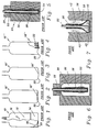
- a double two-part mold 24 is used to create a preform 26 of the plastic to be used for the bottle.
- the mold 24 has a neck-producing portion 28 and a bottle-producing portion 30.
- a hollow core pin 32 is inserted into the assembled mold 24 and the preform 26 made by injecting the plastic through a sprew hole at 34.
- the bottle-producing portion 30 of the mold 24 must be a two-part or split mold since the core pin 32 is cylindrical and the preform 26 contains areas of various thickness to provide additional material for various areas of the finished bottle.
- the preform 26 with the core pin 32 therein and the neck-producing portion 28 of the mold 24 in place is removed from the bottle-producing portion 30 following the injection molding procedure and mounted to a blow mold 36 having a bottle-defining cavity 38 therein.
- a blow mold 36 having a bottle-defining cavity 38 therein.
- various considerations relative to the temperature of the preform prior to the actual blow molding step must be accounted for. For purposes of the present discussion, however, they are of no real importance and, therefore, will not be considered.
- the core pin 32 of Makowski is hollow and contains an integral valve (not shown) at the bottom end thereof.
- the valve With the preform 26 positioned within the cavity 38 as shown in Figure 6, the valve is opened and pressurized air 40 injected causing the preform 26 to stretch outward from the bottom up, as indicated by the arrows 42, to fill the cavity 38 and thereby create the final bottle.
- the Makowski patent is not directed to producing a pressure-resistant bottle.
- the variations in thickness of the preform 26 are to provide different amounts of material available for stretching to form various parts of the bottles shown therein which are of complex shape, such as those used for dishwashing liquids and the like. There is no need for the accurate placement of integral reinforcement-producing areas.
- the preform design with respect to the cylindrical core pin 32 makes the use of a more costly and complex two-part or split injection mold for the production of the preform a necessity.
- An object of the present invention is to provide a construction for the bottom or base of one piece plastic container for containing carbonated beverages which is of the champagne type but which resists inversion from internal forces without the necessity of including complex rib structures therein.
- a further object of the present invention is to provide a construction for the bottom or base of a one piece plastic container for containing carbonated beverages which is of the champagne type and formed by the blow molding of a preform wherein the preform is of a construction which can be produced in a simple one-part injection mold.
- Another object of the present invention is to provide a method for the blow molding of a one piece plastic container for containing carbonated beverages which has a bottom or base of the champagne type containing integral reinforcing sections accurately and repeatably positioned during the blow molding process.
- a preform for use in a blow molding process for producing a one-piece plastic container of the champagne base type by expanding in a mold the preform containing material for a neck, sidewall and base of the container and having an open end to form the neck, a sidewall-forming portion of constant thickness and a base-forming portion terminating in a closed end
- the base-forming portion includes an annular thickened portion positioned such that following blowing of the preform the material of the base-forming portion is deposited to form an inward sloping base portion which is of a thickness sufficient to resist self-deformation and an annular peripheral chime having a moment arm therearound, the chime having an integral reinforcing hoop formed therein to prevent unrolling and radial stretching of the chime thereby to prevent inversion of the inward sloping base portion; and in that said preform, at the point where said sidewall-forming portion and said base-forming portion meet, has an annular surface, or
- a one-piece plastic container, blow-molded from a preform, of the champagne base type having a neck, sidewall and base having an annular peripheral chime surrounding an inward sloping base portion for resisting inversion of the base due to internal pressure when containing carbonated beverages is characterized in that the inward sloping base portion is of a thickness sufficient to resist self-deformation and to create a foment arm around the chime to prevent unrolling and radial stretching of the chime; and the chime is of a thickness sufficient to create an integrated reinforcing hoop to prevent unrolling and radial stretching of said chime which would otherwise allow inversion of the inward sloping base portion.
- the present invention is directed to a free-standing, one piece plastic bottle, preferrably of PET (polyethylene terephthalate), for carbonated beverages having a champagne bottle type shaped base of controlled thickness to provide an annular chime to provide stable upright standing ability wherein the thickness of the bottom is controlled to provide adequate resistance to internal pressure, that thickness being derived from a varying thickness in the preform.
- the base of the present invention incorporates an integral reinforcing ring that runs horizontally in the hoop direction. The reinforcing ring is placed in a location within the base of the bottle that has a moment arm trying to invert the base and provides sufficient strength to withstand that moment arm and keep the push up of the bottom intact.
- a principle feature is that the shape of the preform's interior and exterior walls are ever decreasing in diameter from the neck to the base so that it may be easily removed from a suitable core and injection mold cavity thereby avoiding the need for a split mold as in the Makowski teaching.
- the stability of the chime radius is critical to the thermal performance of pressurized containers. Any movement of the chime due to the downward pressure exerted by the product pressure on the base (referred to as "creep") at ambient or elevated temperatures typically results in excessive container lean (perpendicularly), height increase, and fill level drop.
- the resistance to movement of the contact radius (chime) at a given temperature and pressure is a function of the chime radius itself, the wall thickness at the chime, and the total base contact diameter (which defines total base force at a given product pressure).
- Base construction for a bottle according to the present invention is shown in detailed cross-section in Figure 3.
- the sidewalls 16 are of typical construction and thickness.
- the shape of the base is also typical, meaning that the basic blow molds therefor can be retained.
- the outside radius of the chime 20 is also substantially the same as usual.
- the thickness of the chime 20 is such as to create an internal/integral reinforcing hoop 44 connected to a thickened base portion 46 extending between the reinforcing hoop 44 and the center of the base 14′.
- the present invention deviates from the teachings of Makowski in several major ways.
- the preform and core rod employed in the present invention are such that the shape of the preform's interior and exterior walls are ever decreasing in diameter from the neck to the base so that it may be easily removed from the core and the injection mold cavity, thereby avoiding the need for a split mold.
- the preform is axially stretched in the sidewall-producing area prior to blowing so as to assure less distortion and more accurate placement of the base-producing portion thereof.
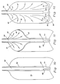
- Figure 9 shows in detail one embodiment of a stretch rod 50 inserted into a preform 26′ as employed in the present invention. While the form of the single piece injection mold and associated core rod which can be employed to produce the preform 26′ is not shown, those skilled in the art will readily recognize the requirements thereof from the shape of the preform 26′ itself.
- the preform 26′ is composed of two parts - a sidewall-producing portion, generally indicated as 52, and a base-producing portion, generally indicated as 54.
- the sidewall-producing portion 52 is of substantially constant thickness so as to produce the constant thickness sidewalls 16 of the finished bottle.
- the exterior surface 56 of the preform 26′ in the sidewall-producing portion 52 tapers inward slightly from the top to the bottom as does the exterior surface 58 of the core rod used to produce it (not shown) in the same area.
- the base-producing portion 54 of the preform 26′ includes thickened area 62 which ultimately forms the reinforcing hoop 44.
- the exterior surface 64 of the preform 26′ in the base-producing portion 54 tapers inward more radically from the top to the bottom while the exterior surface 66 of the core rod use to produce it (not shown) in the same area tapers only slightly while being of significantly smaller diameter.
- the preform 26′ contains an annular nub 67 which is engaged by a matching annular goove 69 in the end of the stretch rod 50. The purpose thereof will be described in detail shortly.
- the shape and placement of the annular nub 67 is such as to allow it to be produced in a one piece mold.
- the outside diameter of the stretch rod 50 at each point along the length thereof must be slightly less than the inside diameter of the preform 26′ at the corresponding point and, therefore, there is a slight gap between the two in most places except at the point of contact with the nub 67.
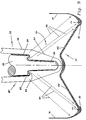
- the preform 26′ is positioned within a bottle-defining cavity 38 of a blow mold such as previously described with respect to Figures 5-7.
- the neck-producing portion 28 (which remains substantially the same) and the mold itself are not shown.
- the bottom of the preform 26′ is initially placed close to but not in contact with the bottom of the cavity 38.
- appropriate heating of the preform 26′ to blow molding temperatures in a manner well known to those skilled in the blow molding art for the materials employed will have been accomplished at this point. Spacing the bottom of the preform 26′ from the bottom of the cavity 38 provides room for the preform 26′ to move longitudinally to disengage the nub 67 from the groove 69 so that the base-producing portion 54 can then move properly to its desired final position
- pressurized air 40 is then injected between the stretch rod 50 and the preform 26′ at the top causing the preform 26′ to separate from the core rod 50, stretch, and form the sidewalls 16 of the bottle from the top down.
- the base-producing portion 54 very little radial stretching takes place as that portion, which is positioned last, lays over to form the base 14′ including the reinforcing hoop 44 within the chime 20 as desired.
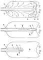
- FIG. 13-15 A second, and preferred, approach is shown in Figures 13-15.
- a second embodiment of the preform 26′ is also shown therein wherein the base-producing portion 54 has an exterior surface 58 which is an extension of the exterior surface 56 above it and terminates in a rounded tip.
- the preform 26′ is foreshortened in length as it comes from its mold. It is initially placed within the bottle-defining cavity 38 as in the previous embodiment. The stretch rod 50, however, is extendable and, as depicted in Figure 14, it is then pushed downward as indicated by the arrow 68 until the bottom of the preform 26′ is positioned close adjacent (but spaced from) the bottom of the cavity 38 as in Figure 10 of the previous embodiment.
- the sidewall-producing portion 52 of the preform 26′ is stretched longitudinally. Because the nub 67 is engaged by the groove 69 and there is a gap between the preform 26′ and the stretch rod 50 elsewhere, however, the stretching forces are generally applied at the point of the nub 67 and groove 69 and virtually all the stretching takes place in the sidewall-producing portion 52 and the base-producing portion 54 is minimally stretched, if at all (i.e. 0-2x), and remains relatively undistorted. As is well known by those skilled in the art, preferred performance is obtained in the bi-axial blow molding of PET containers with proper longitudinal and axial stretching of the material during the molding process. The above-described physical stretching process performs two functions.
- a beneficial side effect of the nub 67 in the method of either Figures 10-12 or 13-15 is its ability to indicate proper placement of the base-producing portion. Since the PET plastic is transparent and a portion of the nub 67 remains distinctly apparent on the inner surface of the chime 20, the radial position of the nub 67 following the blow molding process is visible from outside the final bottle. Its radial position can be used in the quality assurance process to determine if the base-producing portion is properly placed, or radially too far in or too far out. By adjusting the process parameters and checking the results by means of the position of the nub 67 in the final product, accurate placement of the hoop 44 within the chime 20 can be repeatably achieved.
- the nub has an annular air gap between itself and the main body of the preform 26′.
- This air gap is useful and beneficial in minimizing the heat which is directed at the preform 26′ in a reheat process which might be employed in a conventional manner as part of the process by those skilled in the art.
- the resultant relative colder portion of the preform 26′ will then have less tendency to stretch, thus maximizing the material thickness in the chime 20.
- the stretch rod 50′ has an annular recessed flange like portion 75 on its lower tapered end which engages with a protruding portion 73 on the lower end of preform 26 ⁇ .
- the engagement of the recess portion 75 of the stretch rod with the protruding portion 73 of the preform 26 ⁇ results in a substantially equal longitudinal stretching of the sidewall-forming portion 52′ of the preform until the base-forming portion 54′ of the preform abuts or is closely adjacent a downwardly directed apex in the bottom center portion of the mold. Thereafter, the blowing process can proceed to result in a substantially uniform blown container.
- the arrangement shown in Figure 18 is also a non-interlocking engagement which allows the base-forming portion 54′ of the preform 26 ⁇ to be easily laid at any desired location during the blowing stage.
- the parameters of the recess portion 75 and protruding portion 73 i.e. their overall dimensions, inclined angles, etc.
- the parameters of the recess portion 75 and protruding portion 73 will influence how much material is deposited on chime 20 and where the deposits will occur. By controlling these parameters, one can adequately control the thickness of any desired portion of the base.
- the arrangement shown in Figure 9, which includes the nub 67, works best in an intergrated blow molding system.
- the arrangement of Figure 18 is also suitable for an integrated system as the engagement of recessed portion 75 and portion 73 provides the desired stretch of the side walls relative to the base portion during stretching prior to blowing. The reason for this is that in an integrated system the entire preform 26′ is still relatively hot when the blow molding operation begins and thus the base-forming portion 54 of the preform is malleable and has a tendency to yield during the stretching process.
- the employment of nubs 67, which engage with annular groove 69, minimizes the amount of stretching occuring in base-forming portion 54′.
- nubs 67 are not as important and so the preform may have a pencil shaped configuration (see Figure 17) with the modified pencil shaped configuration (see Figure 18) also being suitable.
- the reason the nubs are not required is because the preform is substantially cooled when it enters into the blowing stage and so it must be heated before the stretching operation. Consequently, the heat applied to soften the preform 26 ⁇ can be controlled and directed as desired to produce a desired temperature distribution between the sidewall-forming portion 52′ and the base forming portion 54′ of the preform 26 ⁇ .
- the nubs 67 are not as critical in the non-integrated system.
- the prior art Adomaitis patent teaches a truncated hemispherical base which allows too much stretching of the preform.
- the preferred container design of the present invention has an angular or slightly radiused section between the chime and bottom portion of the container body so that a relatively small gradual transition exists between these two components.
- the angular section intercepts the expansion of the preform, during the blowing process, and allows only moderate stretching of the base portion. Consequently, better control over the placement of the thickened portion of the preform in the chime area is achieved and this, in turn, results in better reinforcement characteristics for the container.
- Adomaitis teaches an upwardly oriented apex in its concave base while the preferred mold design of the present invention has a downwardly directed apex which helps locate and center the preform, relative to the base, and minimizes stretching at the gate nub of the preform to prevent it from cracking (it is a highly crystalline region).
- the apex also moderates the orientation of the bottom of the preform which allows proper placement of the preform material in the rest of the push-up and chime areas.
- the optional inner nubs of the present preform act as a locating and locking device which interact with the stretch rod. The engagement of the inner nubs and the stretch rod minimize the amount of stretch occurring in the base of the preform while allowing the body of the preform to have maximum orientation.
- a secondary purpose of the nub is to act as a visual reference to see how evenly and where the thickened portion of the preform is located once blown into a container. Consequently, unlike Adomaitis, the nub is not provided for strengthening the base and the thickness of the nub relative to the total thickness desired in the chime is inconsequential.
- the present invention has provided many facets to achieve its various objectives including a novel base design, a novel construction for a preform employed to produce the base by blow molding methods, and a novel method of blow molding a container to achieve accurate placement of portions of the preform employed therein into the final product which includes versions providing a self-generating indicator giving the ability to visually perform quality assurance on the final product to assure such placement.
- bottles is meant to include containers such as jars and cans, including those which contain a plastic base and metal lid and those which are formed by preparing the bottle as described above and then removing the top portion and attaching a metal lid thereto.
- carbonated is meant to include fluids placed under pressure including naturally carbonated as well as artificially carbonated liquids.
Landscapes
- Engineering & Computer Science (AREA)
- Mechanical Engineering (AREA)
- Manufacturing & Machinery (AREA)
- Physics & Mathematics (AREA)
- Geometry (AREA)
- Ceramic Engineering (AREA)
- Blow-Moulding Or Thermoforming Of Plastics Or The Like (AREA)
- Processing And Handling Of Plastics And Other Materials For Molding In General (AREA)
- Moulds For Moulding Plastics Or The Like (AREA)
Priority Applications (1)
| Application Number | Priority Date | Filing Date | Title |
|---|---|---|---|
| EP19930113885 EP0577155B1 (en) | 1987-05-29 | 1988-05-23 | One-piece self-standing blow molded plastic containers |
Applications Claiming Priority (4)
| Application Number | Priority Date | Filing Date | Title |
|---|---|---|---|
| US55647 | 1987-05-29 | ||
| US07/055,647 US4780257A (en) | 1987-05-29 | 1987-05-29 | One piece self-standing blow molded plastic bottles |
| US07/129,642 US4889752A (en) | 1987-05-29 | 1987-12-07 | One piece self-standing blow molded plastic containers |
| US129642 | 1987-12-07 |
Related Child Applications (2)
| Application Number | Title | Priority Date | Filing Date |
|---|---|---|---|
| EP93113885.3 Division-Into | 1988-05-23 | ||
| EP19930113885 Division EP0577155B1 (en) | 1987-05-29 | 1988-05-23 | One-piece self-standing blow molded plastic containers |
Publications (3)
| Publication Number | Publication Date |
|---|---|
| EP0293147A2 EP0293147A2 (en) | 1988-11-30 |
| EP0293147A3 EP0293147A3 (en) | 1991-10-02 |
| EP0293147B1 true EP0293147B1 (en) | 1996-01-17 |
Family
ID=26734475
Family Applications (2)
| Application Number | Title | Priority Date | Filing Date |
|---|---|---|---|
| EP19930113885 Expired - Lifetime EP0577155B1 (en) | 1987-05-29 | 1988-05-23 | One-piece self-standing blow molded plastic containers |
| EP19880304634 Expired - Lifetime EP0293147B1 (en) | 1987-05-29 | 1988-05-23 | One piece self-standing blow molded plastic containers |
Family Applications Before (1)
| Application Number | Title | Priority Date | Filing Date |
|---|---|---|---|
| EP19930113885 Expired - Lifetime EP0577155B1 (en) | 1987-05-29 | 1988-05-23 | One-piece self-standing blow molded plastic containers |
Country Status (13)
| Country | Link |
|---|---|
| US (1) | US4889752A (es) |
| EP (2) | EP0577155B1 (es) |
| JP (1) | JP2619688B2 (es) |
| KR (1) | KR960007288B1 (es) |
| AR (1) | AR243112A1 (es) |
| AT (2) | ATE133107T1 (es) |
| AU (1) | AU605869B2 (es) |
| BR (1) | BR8802603A (es) |
| CA (1) | CA1306206C (es) |
| DE (2) | DE3855880T2 (es) |
| ES (2) | ES2082751T3 (es) |
| MX (1) | MX167255B (es) |
| NZ (1) | NZ224665A (es) |
Families Citing this family (37)
| Publication number | Priority date | Publication date | Assignee | Title |
|---|---|---|---|---|
| US5198248A (en) * | 1990-03-05 | 1993-03-30 | Continental Pet Technologies, Inc. | Blow mold for forming a refillable polyester container |
| US5066528A (en) * | 1990-03-05 | 1991-11-19 | Continental Pet Technologies, Inc. | Refillable polyester container and preform for forming the same |
| US5104706A (en) * | 1990-03-15 | 1992-04-14 | Continental Pet Technologies, Inc. | Preform for hot fill pressure container |
| US5024340A (en) * | 1990-07-23 | 1991-06-18 | Sewell Plastics, Inc. | Wide stance footed bottle |
| JPH0735085B2 (ja) * | 1990-10-05 | 1995-04-19 | 日精エー・エス・ビー機械株式会社 | 2軸延伸結晶性樹脂容器およびその製造方法 |
| US5615790A (en) * | 1990-11-15 | 1997-04-01 | Plastipak Packaging, Inc. | Plastic blow molded freestanding container |
| US5064080A (en) * | 1990-11-15 | 1991-11-12 | Plastipak Packaging, Inc. | Plastic blow molded freestanding container |
| JP2557557Y2 (ja) * | 1991-02-12 | 1997-12-10 | ミネベア株式会社 | キースイッチ |
| US5290506A (en) * | 1991-04-30 | 1994-03-01 | Nissei Asb Machine Co., Ltd. | Process of injection stretch blow molding hollow article having thick-walled bottom |
| US5455088A (en) * | 1991-12-24 | 1995-10-03 | Constar Plastics Inc. | Preform for continuous standing ring bottle |
| US5664695A (en) * | 1995-01-06 | 1997-09-09 | Plastipak Packaging, Inc. | Plastic blow molded freestanding container |
| US5614148A (en) * | 1995-01-30 | 1997-03-25 | Dtl Technology Limited Partnership | One piece self-standing blow molded plastic containers made from a monobase preform |
| US6019591A (en) * | 1995-03-22 | 2000-02-01 | Pepsico, Inc. | System for molding a footed plastic bottle |
| EP0739703B1 (de) * | 1995-04-27 | 1997-05-02 | Continental PET Deutschland GmbH | Bodengeometrie von wiederverwendbaren PET-Behältern |
| US5850932A (en) * | 1997-07-07 | 1998-12-22 | Dtl Monofoot Limited Partnership | Base design for one piece self-standing blow molded plastic containers |
| US6123211A (en) | 1997-10-14 | 2000-09-26 | American National Can Company | Multilayer plastic container and method of making the same |
| AUPP844999A0 (en) * | 1999-02-02 | 1999-02-25 | RUSSELL, Graeme John | Apparatus for stretch forming an article |
| JP2001029433A (ja) * | 1999-07-15 | 2001-02-06 | Taisei Kako Co Ltd | Pes製インジェクションブロー成形ほ乳瓶、並びに、その製造方法 |
| US20030061014A1 (en) * | 2001-09-17 | 2003-03-27 | Cheng J. John | Method of designing a champagne-type base for a plastic container |
| US6634517B2 (en) | 2001-09-17 | 2003-10-21 | Crown Cork & Seal Technologies Corporation | Base for plastic container |
| US6769561B2 (en) * | 2001-12-21 | 2004-08-03 | Ball Corporation | Plastic bottle with champagne base |
| US20060255049A1 (en) * | 2002-08-09 | 2006-11-16 | Fort James Corporation | Stretch blow-molded stackable tumbler |
| US8567635B2 (en) * | 2003-11-05 | 2013-10-29 | By The Glass, Llc | Wine glass |
| US7886924B2 (en) | 2003-11-05 | 2011-02-15 | By The Glass, Llc | Wine glass |
| US7416089B2 (en) * | 2004-12-06 | 2008-08-26 | Constar International Inc. | Hot-fill type plastic container with reinforced heel |
| ITMI20061922A1 (it) * | 2006-10-06 | 2008-04-07 | Gianfilippo Pagliacci | Preforma di materiale plastico perfezionata. |
| US20100012617A1 (en) * | 2008-07-16 | 2010-01-21 | Ulibarri Scott M | Plastic bottle with superior top load strength |
| US20110049083A1 (en) | 2009-09-01 | 2011-03-03 | Scott Anthony J | Base for pressurized bottles |
| US8741206B2 (en) * | 2009-12-17 | 2014-06-03 | Eastman Chemical Company | Method and apparatus for stretch blow molding a container |
| US8968636B2 (en) * | 2010-10-15 | 2015-03-03 | Discma Ag | Stretch rod system for liquid or hydraulic blow molding |
| DE102011018583A1 (de) * | 2011-04-08 | 2012-10-11 | Khs Corpoplast Gmbh | Vorrichtung zur Blasformung von Behältern |
| DE102015100346A1 (de) | 2015-01-12 | 2016-07-14 | Khs Corpoplast Gmbh | Gebinde, ausweisend Behälter mit verstärktem Wandbereich |
| WO2017065803A1 (en) * | 2015-10-16 | 2017-04-20 | Amcor Limited | Etched preform tip |
| DE102016110600A1 (de) | 2016-06-08 | 2017-12-28 | Khs Corpoplast Gmbh | Verfahren und Vorrichtung zum Herstellen eines Gebindes sowie Gebinde |
| WO2018078502A1 (en) * | 2016-10-25 | 2018-05-03 | Alan Mark Crawley | Improvements in double-walled containers |
| EP3745927A4 (en) * | 2018-01-29 | 2021-08-04 | Alan Mark Crawley | PROCESS AND APPARATUS IMPROVEMENTS FOR INTEGRATED DOUBLE WALL CONTAINER STRUCTURES |
| FR3134534B1 (fr) * | 2022-04-13 | 2024-03-08 | Sidel Participations | Tige d’étirage et de refroidissement pour la formation de récipients |
Family Cites Families (55)
| Publication number | Priority date | Publication date | Assignee | Title |
|---|---|---|---|---|
| US3031095A (en) * | 1960-01-11 | 1962-04-24 | William C Loughran | Bottle for christening ships |
| NL264149A (es) * | 1960-05-02 | 1900-01-01 | ||
| US3043461A (en) * | 1961-05-26 | 1962-07-10 | Purex Corp | Flexible plastic bottles |
| GB1114304A (en) * | 1964-06-12 | 1968-05-22 | American Can Co | Method and device for forming a hollow plastic article |
| DE1607895B2 (de) * | 1967-07-20 | 1977-02-10 | 4P Nicolaus Kempten Gmbh, 8960 Kempten | Druckfeste kunststoff-flasche |
| US3598270A (en) * | 1969-04-14 | 1971-08-10 | Continental Can Co | Bottom end structure for plastic containers |
| US3643829A (en) * | 1969-08-22 | 1972-02-22 | Lever Brothers Ltd | Pressure-resistant plastics bottle |
| DE2004190C3 (de) * | 1970-01-30 | 1979-06-13 | Scharf, Friedrich, Dr., 7000 Stuttgart | Unter Überdruck stehender Verpackungsbehälter |
| US3720339A (en) * | 1970-09-24 | 1973-03-13 | Monsanto Co | Plastic container for pressurized materials-a |
| FR2132543B1 (es) * | 1971-04-08 | 1974-10-31 | Saint Gobain Pont A Mousson | |
| US3718229A (en) * | 1971-10-26 | 1973-02-27 | Du Pont | Noneverting bottom for thermoplastic bottles |
| BE790814A (fr) * | 1971-11-01 | 1973-04-30 | Du Pont | Fond ne se retournant pas pour bouteille en matiere thermoplastique |
| US3759410A (en) * | 1971-12-15 | 1973-09-18 | Owens Illinois Inc | Pressure resistant plastic container |
| US3757978A (en) * | 1971-12-22 | 1973-09-11 | Phillips Petroleum Co | Biaxially oriented blow molded article with ribs parallel to seam |
| US3917095A (en) * | 1972-05-04 | 1975-11-04 | Phillips Petroleum Co | Oriented article having bead attached by tapered stem |
| US3934743A (en) * | 1972-12-29 | 1976-01-27 | American Can Company | Blow molded, oriented plastic bottle and method for making same |
| US3870181A (en) * | 1973-02-12 | 1975-03-11 | Monsanto Co | Molecularly oriented bottle |
| US3900120A (en) * | 1973-02-12 | 1975-08-19 | Monsanto Co | Preforms for forming pressurized containers |
| US3871541A (en) * | 1973-02-26 | 1975-03-18 | Continental Can Co | Bottom structure for plastic containers |
| US3881621A (en) * | 1973-07-02 | 1975-05-06 | Continental Can Co | Plastic container with noneverting bottom |
| US4024975A (en) * | 1974-09-16 | 1977-05-24 | Owens-Illinois, Inc. | Reinforced bottle |
| US3948404A (en) * | 1974-11-14 | 1976-04-06 | E. I. Du Pont De Nemours And Company | Composite package for containing pressurized fluids |
| US4036926A (en) * | 1975-06-16 | 1977-07-19 | Owens-Illinois, Inc. | Method for blow molding a container having a concave bottom |
| US4256231A (en) * | 1976-10-21 | 1981-03-17 | Henkel Kommanditgesellschaft Auf Aktien (Henkel Kgaa) | Container with a synthetic lining impermeable to liquids and method of making |
| DE2717365A1 (de) * | 1977-04-20 | 1978-10-26 | Bekum Maschf Gmbh | Verfahren zur herstellung von hohlkoerpern aus thermoplastischem kunststoff |
| US4108324A (en) * | 1977-05-23 | 1978-08-22 | The Continental Group, Inc. | Ribbed bottom structure for plastic container |
| SE417592B (sv) * | 1978-03-13 | 1981-03-30 | Plm Ab | Behallare av teromplastiskt plastmaterial med i behallarveggen inbyggda forsterkningar, samt forfarande for framstellning av en sadan behallare |
| JPS5541319U (es) * | 1978-09-08 | 1980-03-17 | ||
| JPS5579236A (en) * | 1978-12-06 | 1980-06-14 | Yoshino Kogyosho Co Ltd | Bottle made of twooaxissextended synthetic resin and method of manufacturing said bottle |
| JPS5579239A (en) * | 1978-12-13 | 1980-06-14 | Yoshino Kogyosho Co Ltd | Innprocess material for making bottole of twooaxissextended synthetic resin and method of using said material |
| JPS5852913Y2 (ja) * | 1979-01-16 | 1983-12-02 | 株式会社吉野工業所 | 二軸延伸される合成樹脂製壜成形用中間素材 |
| US4219124A (en) * | 1979-04-20 | 1980-08-26 | Owens-Illinois, Inc. | Plastic package |
| US4287150A (en) * | 1979-05-21 | 1981-09-01 | Hercules Incorporated | Method and apparatus for injection blow molding an article with improved detail definition |
| US4267144A (en) * | 1979-07-03 | 1981-05-12 | The Continental Group, Inc. | Process of reducing blowing cycle for blow molded containers |
| US4335821A (en) * | 1979-07-03 | 1982-06-22 | The Continental Group, Inc. | Blow molded plastic material bottle bottom |
| US4247012A (en) * | 1979-08-13 | 1981-01-27 | Sewell Plastics, Inc. | Bottom structure for plastic container for pressurized fluids |
| US4241839A (en) * | 1979-08-14 | 1980-12-30 | Sewell Plastics, Inc. | Base-cup for assuring vertical alignment of semi-hemispherically bottomed bottles |
| US4249667A (en) * | 1979-10-25 | 1981-02-10 | The Continental Group, Inc. | Plastic container with a generally hemispherical bottom wall having hollow legs projecting therefrom |
| US4261948A (en) * | 1979-11-27 | 1981-04-14 | The Continental Group, Inc. | Method of increasing the wall thickness of a bottom structure of a blown plastic material container |
| US4525401A (en) * | 1979-11-30 | 1985-06-25 | The Continental Group, Inc. | Plastic container with internal rib reinforced bottom |
| US4334627A (en) * | 1979-11-27 | 1982-06-15 | The Continental Group, Inc. | Blow molded plastic bottle |
| US4442944A (en) * | 1980-03-03 | 1984-04-17 | Yoshino Kogyosho Co., Ltd. | Saturated polyester resin bottle and stand |
| NL8102376A (nl) * | 1980-05-29 | 1981-12-16 | Plm Ab | Werkwijze en inrichting voor het vormen van een houder. |
| AU7923382A (en) * | 1981-02-23 | 1982-09-02 | Continental Group Inc., The | Blow moulding pre-form |
| US4463056A (en) * | 1981-10-26 | 1984-07-31 | Owens-Illinois, Inc. | Thermoplastic container parison |
| US4576843A (en) * | 1981-11-23 | 1986-03-18 | The Continental Group, Inc. | Blow molded containers and method of forming the same |
| US4483891A (en) * | 1981-12-11 | 1984-11-20 | Ball Corporation | Multilayered tube having a barrier layer |
| EP0092904B1 (en) * | 1982-04-12 | 1986-06-04 | Siegfried Shankar Roy | Injection blow molding apparatus |
| US4403706A (en) * | 1982-06-08 | 1983-09-13 | The Continental Group, Inc. | Plastic container with hollow internal rib reinforced bottom and method of forming the same |
| US4436216A (en) * | 1982-08-30 | 1984-03-13 | Owens-Illinois, Inc. | Ribbed base cups |
| US4519977A (en) * | 1982-09-27 | 1985-05-28 | Toyo Seikan Kaisha Limited | Method for making a plastic container |
| US4502607A (en) * | 1983-06-21 | 1985-03-05 | Continental Plastic Containers, Inc. | Bulge resistant bottle bottom |
| JPS6076613U (ja) * | 1983-10-31 | 1985-05-29 | 日精エー・エス・ビー機械株式会社 | 耐熱性合成樹脂びん |
| US4755404A (en) * | 1986-05-30 | 1988-07-05 | Continental Pet Technologies, Inc. | Refillable polyester beverage bottle and preform for forming same |
| US4725464A (en) * | 1986-05-30 | 1988-02-16 | Continental Pet Technologies, Inc. | Refillable polyester beverage bottle and preform for forming same |
-
1987
- 1987-12-07 US US07/129,642 patent/US4889752A/en not_active Expired - Lifetime
-
1988
- 1988-05-17 NZ NZ22466588A patent/NZ224665A/xx unknown
- 1988-05-17 MX MX1150288A patent/MX167255B/es unknown
- 1988-05-17 CA CA 567038 patent/CA1306206C/en not_active Expired - Fee Related
- 1988-05-20 AU AU16483/88A patent/AU605869B2/en not_active Ceased
- 1988-05-23 AT AT88304634T patent/ATE133107T1/de not_active IP Right Cessation
- 1988-05-23 ES ES88304634T patent/ES2082751T3/es not_active Expired - Lifetime
- 1988-05-23 DE DE19883855880 patent/DE3855880T2/de not_active Expired - Fee Related
- 1988-05-23 EP EP19930113885 patent/EP0577155B1/en not_active Expired - Lifetime
- 1988-05-23 EP EP19880304634 patent/EP0293147B1/en not_active Expired - Lifetime
- 1988-05-23 DE DE19883854903 patent/DE3854903T2/de not_active Expired - Fee Related
- 1988-05-23 AT AT93113885T patent/ATE151688T1/de not_active IP Right Cessation
- 1988-05-23 ES ES93113885T patent/ES2100407T3/es not_active Expired - Lifetime
- 1988-05-27 BR BR8802603A patent/BR8802603A/pt not_active IP Right Cessation
- 1988-05-28 KR KR1019880006312A patent/KR960007288B1/ko not_active IP Right Cessation
- 1988-05-30 JP JP13048788A patent/JP2619688B2/ja not_active Expired - Lifetime
-
1989
- 1989-03-13 AR AR31340489A patent/AR243112A1/es active
Also Published As
| Publication number | Publication date |
|---|---|
| ES2082751T3 (es) | 1996-04-01 |
| BR8802603A (pt) | 1988-12-27 |
| KR960007288B1 (ko) | 1996-05-30 |
| DE3855880D1 (de) | 1997-05-22 |
| AR243112A1 (es) | 1993-07-30 |
| ES2100407T3 (es) | 1997-06-16 |
| JPS645815A (en) | 1989-01-10 |
| ATE151688T1 (de) | 1997-05-15 |
| EP0577155B1 (en) | 1997-04-16 |
| EP0293147A2 (en) | 1988-11-30 |
| AU605869B2 (en) | 1991-01-24 |
| DE3854903T2 (de) | 1996-09-05 |
| DE3854903D1 (de) | 1996-02-29 |
| DE3855880T2 (de) | 1997-07-31 |
| MX167255B (es) | 1993-03-12 |
| KR880013675A (ko) | 1988-12-21 |
| US4889752A (en) | 1989-12-26 |
| EP0577155A1 (en) | 1994-01-05 |
| ATE133107T1 (de) | 1996-02-15 |
| EP0293147A3 (en) | 1991-10-02 |
| JP2619688B2 (ja) | 1997-06-11 |
| NZ224665A (en) | 1989-12-21 |
| AU1648388A (en) | 1988-12-01 |
| CA1306206C (en) | 1992-08-11 |
Similar Documents
| Publication | Publication Date | Title |
|---|---|---|
| EP0293147B1 (en) | One piece self-standing blow molded plastic containers | |
| US4780257A (en) | One piece self-standing blow molded plastic bottles | |
| US4927679A (en) | Preform for a monobase container | |
| EP0683029B1 (en) | Biaxially-drawn blow-molded container having excellent heat resistance and method for producing the same | |
| EP0445465B1 (en) | Refillable polyester container and preform for forming the same | |
| EP0379264B1 (en) | Preform for blow moulding refillable polyester beverage bottle | |
| US5104706A (en) | Preform for hot fill pressure container | |
| US4603831A (en) | Mold core member for use in a mold unit for injection molding a plastic material preform for a blow molded container | |
| EP0324102A2 (en) | Method for preparing blow molded plastic container | |
| CA1308370C (en) | Refillable polyester bottle and preform for forming same | |
| CA1164370A (en) | Synthetic resin made thin-walled bottle and method of producing same | |
| IE69387B1 (en) | Preform for blow moulding refillable polyester beverage bottle |
Legal Events
| Date | Code | Title | Description |
|---|---|---|---|
| PUAI | Public reference made under article 153(3) epc to a published international application that has entered the european phase |
Free format text: ORIGINAL CODE: 0009012 |
|
| AK | Designated contracting states |
Kind code of ref document: A2 Designated state(s): AT BE CH DE ES FR GB GR IT LI LU NL SE |
|
| PUAL | Search report despatched |
Free format text: ORIGINAL CODE: 0009013 |
|
| AK | Designated contracting states |
Kind code of ref document: A3 Designated state(s): AT BE CH DE ES FR GB GR IT LI LU NL SE |
|
| 17P | Request for examination filed |
Effective date: 19920327 |
|
| 17Q | First examination report despatched |
Effective date: 19930316 |
|
| GRAA | (expected) grant |
Free format text: ORIGINAL CODE: 0009210 |
|
| AK | Designated contracting states |
Kind code of ref document: B1 Designated state(s): AT BE CH DE ES FR GB GR IT LI LU NL SE |
|
| PG25 | Lapsed in a contracting state [announced via postgrant information from national office to epo] |
Ref country code: NL Free format text: LAPSE BECAUSE OF FAILURE TO SUBMIT A TRANSLATION OF THE DESCRIPTION OR TO PAY THE FEE WITHIN THE PRESCRIBED TIME-LIMIT Effective date: 19960117 Ref country code: LI Effective date: 19960117 Ref country code: GR Free format text: LAPSE BECAUSE OF FAILURE TO SUBMIT A TRANSLATION OF THE DESCRIPTION OR TO PAY THE FEE WITHIN THE PRESCRIBED TIME-LIMIT Effective date: 19960117 Ref country code: CH Effective date: 19960117 Ref country code: AT Effective date: 19960117 |
|
| REF | Corresponds to: |
Ref document number: 133107 Country of ref document: AT Date of ref document: 19960215 Kind code of ref document: T |
|
| XX | Miscellaneous (additional remarks) |
Free format text: TEILANMELDUNG 93113885.3 EINGEREICHT AM 23/05/88. |
|
| ITF | It: translation for a ep patent filed |
Owner name: BARZANO' E ZANARDO ROMA S.P.A. |
|
| REF | Corresponds to: |
Ref document number: 3854903 Country of ref document: DE Date of ref document: 19960229 |
|
| REG | Reference to a national code |
Ref country code: ES Ref legal event code: FG2A Ref document number: 2082751 Country of ref document: ES Kind code of ref document: T3 |
|
| PG25 | Lapsed in a contracting state [announced via postgrant information from national office to epo] |
Ref country code: SE Effective date: 19960417 |
|
| ET | Fr: translation filed | ||
| PG25 | Lapsed in a contracting state [announced via postgrant information from national office to epo] |
Ref country code: LU Free format text: LAPSE BECAUSE OF NON-PAYMENT OF DUE FEES Effective date: 19960531 |
|
| NLV1 | Nl: lapsed or annulled due to failure to fulfill the requirements of art. 29p and 29m of the patents act | ||
| REG | Reference to a national code |
Ref country code: CH Ref legal event code: PL |
|
| PLBE | No opposition filed within time limit |
Free format text: ORIGINAL CODE: 0009261 |
|
| STAA | Information on the status of an ep patent application or granted ep patent |
Free format text: STATUS: NO OPPOSITION FILED WITHIN TIME LIMIT |
|
| 26N | No opposition filed | ||
| PGFP | Annual fee paid to national office [announced via postgrant information from national office to epo] |
Ref country code: FR Payment date: 19990511 Year of fee payment: 12 |
|
| PGFP | Annual fee paid to national office [announced via postgrant information from national office to epo] |
Ref country code: GB Payment date: 19990519 Year of fee payment: 12 |
|
| PGFP | Annual fee paid to national office [announced via postgrant information from national office to epo] |
Ref country code: ES Payment date: 19990524 Year of fee payment: 12 |
|
| PGFP | Annual fee paid to national office [announced via postgrant information from national office to epo] |
Ref country code: DE Payment date: 19990525 Year of fee payment: 12 |
|
| PGFP | Annual fee paid to national office [announced via postgrant information from national office to epo] |
Ref country code: BE Payment date: 19990728 Year of fee payment: 12 |
|
| PG25 | Lapsed in a contracting state [announced via postgrant information from national office to epo] |
Ref country code: GB Free format text: LAPSE BECAUSE OF NON-PAYMENT OF DUE FEES Effective date: 20000523 |
|
| PG25 | Lapsed in a contracting state [announced via postgrant information from national office to epo] |
Ref country code: ES Free format text: THE PATENT HAS BEEN ANNULLED BY A DECISION OF A NATIONAL AUTHORITY Effective date: 20000524 |
|
| PG25 | Lapsed in a contracting state [announced via postgrant information from national office to epo] |
Ref country code: BE Free format text: LAPSE BECAUSE OF NON-PAYMENT OF DUE FEES Effective date: 20000531 |
|
| BERE | Be: lapsed |
Owner name: DEVTECH INC. Effective date: 20000531 |
|
| GBPC | Gb: european patent ceased through non-payment of renewal fee |
Effective date: 20000523 |
|
| PG25 | Lapsed in a contracting state [announced via postgrant information from national office to epo] |
Ref country code: FR Free format text: LAPSE BECAUSE OF NON-PAYMENT OF DUE FEES Effective date: 20010131 |
|
| PG25 | Lapsed in a contracting state [announced via postgrant information from national office to epo] |
Ref country code: DE Free format text: LAPSE BECAUSE OF NON-PAYMENT OF DUE FEES Effective date: 20010301 |
|
| REG | Reference to a national code |
Ref country code: FR Ref legal event code: ST |
|
| REG | Reference to a national code |
Ref country code: ES Ref legal event code: FD2A Effective date: 20020204 |
|
| PG25 | Lapsed in a contracting state [announced via postgrant information from national office to epo] |
Ref country code: IT Free format text: LAPSE BECAUSE OF NON-PAYMENT OF DUE FEES Effective date: 20050523 |