EP0292932B1 - Verfahren und Vorrichtung zum kontrollierten Abbau einer Aerosolwolke - Google Patents
Verfahren und Vorrichtung zum kontrollierten Abbau einer Aerosolwolke Download PDFInfo
- Publication number
- EP0292932B1 EP0292932B1 EP88108317A EP88108317A EP0292932B1 EP 0292932 B1 EP0292932 B1 EP 0292932B1 EP 88108317 A EP88108317 A EP 88108317A EP 88108317 A EP88108317 A EP 88108317A EP 0292932 B1 EP0292932 B1 EP 0292932B1
- Authority
- EP
- European Patent Office
- Prior art keywords
- cloud
- particles
- sound
- aircraft
- aerosol
- Prior art date
- Legal status (The legal status is an assumption and is not a legal conclusion. Google has not performed a legal analysis and makes no representation as to the accuracy of the status listed.)
- Expired - Lifetime
Links
Images
Classifications
-
- B—PERFORMING OPERATIONS; TRANSPORTING
- B01—PHYSICAL OR CHEMICAL PROCESSES OR APPARATUS IN GENERAL
- B01D—SEPARATION
- B01D51/00—Auxiliary pretreatment of gases or vapours to be cleaned
- B01D51/02—Amassing the particles, e.g. by flocculation
- B01D51/06—Amassing the particles, e.g. by flocculation by varying the pressure of the gas or vapour
- B01D51/08—Amassing the particles, e.g. by flocculation by varying the pressure of the gas or vapour by sound or ultrasound
-
- E—FIXED CONSTRUCTIONS
- E01—CONSTRUCTION OF ROADS, RAILWAYS, OR BRIDGES
- E01H—STREET CLEANING; CLEANING OF PERMANENT WAYS; CLEANING BEACHES; DISPERSING OR PREVENTING FOG IN GENERAL CLEANING STREET OR RAILWAY FURNITURE OR TUNNEL WALLS
- E01H13/00—Dispersing or preventing fog in general, e.g. on roads, on airfields
Definitions
- the invention relates to a method and a device for the controlled degradation of an aerosol cloud with the aid of directed sound waves of high intensity in the audible or ultrasound frequency range.
- Patent document GB-A-1154.020 describes an ultrasound siren for use on ships which emits two sound waves of the same frequency in the range from 16 to 22 kHz, which are shifted in phase by 180 °. The intensity of the sound can be adjusted variably.
- the object of the present invention is a sound system Specify that is particularly suitable for the removal of aerosol clouds from the air in the event of major accidents in nuclear and chemical plants in which radioactive and / or toxic particle clouds are released into the air.
- the dangers for humans and the environment resulting from the atmospheric spread of the dangerous substances over possibly several hundred kilometers can thus be considerably reduced.
- the method aims in particular to influence the particles in such a way that they can be collected. This is not possible with the known methods mentioned.
- the invention accordingly relates to a method for the controlled degradation of an aerosol cloud with the aid of directional sound waves of high intensity in the audible or ultrasound frequency range, characterized in that the sound waves are emitted by an aircraft operating close to the cloud, the frequency spectrum of the wave coming from a fundamental frequency and a superposition frequency of twice the frequency value, which is shifted in phase by 90 ° to the fundamental frequency, so that the cloud particles coagulate and move in the direction of the sound source, and that the particles are then collected on the aircraft.
- This directed, rapid movement of the coagulated particles can be used particularly advantageously to combat dangerous aerosol clouds and to break them down in a controlled manner if the sound transmitter and the means for collecting the particles are directed towards the cloud by an aircraft.
- the disadvantages of the known sound reinforcement techniques that operate from the surface of the earth or water are avoided.
- These disadvantages mainly consist in the fact that the aerosols being controlled can only be sonicated from the same direction, namely from the surface of the earth, that in principle there must always be long distances between the sound transmitter and the cloud, which results in high energy losses in the air, in particular due to acoustic saturation, and that in the best case only an uncontrolled raining down of the aerosols can be achieved, which again causes problems with radioactive and toxic aerosols.
- the density of the particles in the cloud is low, it may be advantageous to introduce seed aerosols into the cloud to be controlled in addition to the sound system, for which an aircraft is again particularly suitable.
- the aerosol cloud can also be fought from several, if necessary different, aircraft, and additionally from a fixed or mobile transmitter station on the ground.
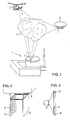
- FIG. 1 shows an aerosol cloud emerging from a damaged nuclear power plant and schematically the application of the method according to the invention to this cloud.
- Fig. 2 shows schematically an apparatus for performing this method for attachment to an airship.
- Fig. 3 shows a sound source with a particle collection device schematically in section.
- An aerosol cloud as can occur in a nuclear facility in a large-scale facility, has the following properties, for example: Cloud diameter: 100 meters Cloud volume: 5x10⁵m3 Particle concentration: 1012m ⁇ 3 Distance between the particles: 100 ⁇ m average particle diameter: 1 ⁇ m Number of particles: 5x10¹⁷ Density of a particle: 1g cm ⁇ 3 Bulk load: 1g m3
- the particle diameters vary widely. If the particle diameter is less than 0.1 ⁇ m, the Braun motion quickly causes a collision of particles with one another and their coagulation. If, on the other hand, the particle diameter is very large, for example larger than 15 ⁇ m, then gravity leads to a rapid sedimentation of these particles and their settling on the ground in the immediate vicinity of the damaged facility. It follows from this that the particularly dangerous particles, which are largely carried away by the atmospheric currents, have diameters between 0.1 and 15 ⁇ m and must be detected by the method according to the invention.
- the invention goes one step further by largely preventing the aerosols from raining onto the ground by generating a drift movement of the particles towards the sound source and collecting the particles in a collecting device on the aircraft.
- the forces responsible for the entire coagulation and drifting process are the mean Stokes force and the mean oseen force.
- the Stokes force is based on the temperature dependence of the Viscosity in a fluid.
- the temperature of the fluid In the case of adiabatic compression of the fluid, caused by a sound wave, the temperature of the fluid first rises and then drops again in the second sound half-wave.
- the product of the fluid velocity and the viscosity gives an average value over a cycle, which leads to a drift of the particle towards the sound source. It can be shown that in air at 20 ° C and at atmospheric pressure a sound wave with a sound pressure level of 151 dB produces a drift at a speed of 0.66 cm / s.
- the so-called oseen force is also effective.
- This force is, for example, in the journal Journ. Acoustic Soc. of America Vol. 22, 1950, pages 319 ff and Vol. 23, 1951, pages 312-315. It is based on the distortion of the waveform at higher amplitudes and is independent of the temperature variation in the sound wave. In contrast, the magnitude and the direction of this force strongly depend on the degree of distortion, in particular on the phase shift between the fundamental frequency and twice the fundamental frequency, provided that the sound wave contains these components in particular. This force is greatest towards the source for a phase difference of + 90 ° between these components.
- Fig. 1 shows a nuclear plant 1 with a reactor vessel 2, which has got a crack 3 in the roof due to an accident. Radioactive substances escape through this crack and form an aerosol cloud 4 in the ambient air with the characteristic values specified further above.
- the invention is intended to spread the radioactive aerosol particles the atmospheric air movements are prevented.
- a sound transmitter e.g. a siren 7 or 9 equipped for emitting the sound signal according to the invention, the sonicated area being indicated by the dashed lines.
- a matrix arrangement 11 of transducer-controlled loudspeakers 12 can also be provided, as is shown schematically in FIG. 2.
- a remote-controlled aircraft can also be steered directly into the cloud, so that the coagulation and drift effect of the sound system becomes even more intense than when sounding from the periphery of the cloud.
- the sound effect is particularly intense when the particles in the aerosol cloud are exposed to a field of standing sound waves.
- This can be achieved, as shown in FIG. 2 in the case of a sound reinforcement device with loudspeakers 12 in a matrix frame 11, by attaching a reflector wall 13 to the frame while leaving an intermediate distance, which of course, like the frame 11, is attached to the airship 8 .
- the scaffold 11 can be equipped with fewer sirens when used on an aircraft than when used at ground stations.
- the distance between the reflector wall 13 and the frame 11 is, for example, 10 m.
- an airship also has the advantage without further control measures to drift with the wind in the cloud.
- a single, simultaneously acting as a loudspeaker and collecting device is shown schematically in section, in which the sound energy is generated directly by means of electrical energy.
- a collecting wall 14 which is permeable to sound waves, on which the drifting particles hit and which, together with a vertically adjustable scraper 15, forms a collector device for the incoming particles.
- the scraper is periodically guided over the surface and conveys the particles into a collecting trough 16, from where they are removed or suctioned off by means not shown.
- the mean osseous force leads to particularly high drift speeds if, according to the invention, the sound waves contain a fundamental frequency (e.g. 20 kHz) and the first harmonic (40 kHz), which is phase-shifted by 90 °, as the main components of the emission spectrum.
- a spectrum can e.g. generated with corresponding electrically controlled piezoelectric or magnetostrictive transducers.
- Acoustic transducers have also been developed that convert up to 80% of the electrical power fed into sound power.
- the method according to the invention can also be operated with correspondingly tuned pipes or sirens or sound generators acting as internal combustion engines if only the sound level is sufficiently high.
- the invention is not limited to the treatment of radioactive aerosol clouds, but can be used wherever undesired aerosol clouds are to be removed from the air. This applies, for example, to chemical accidents, traffic accidents with tank trucks or when fighting high fog banks in the area of airports.
- a gas cloud is specifically to be combated and broken down, it can be pretreated by spraying seed particles such as activated carbon or zeolite into the gas cloud.
- seed particles such as activated carbon or zeolite into the gas cloud.
- the adsorption of the gas on the carbon or zeolite particles is increased at high sound field intensity by the destruction of the viscous boundary layer around the particle. Then the seed particles are sucked off together with the adsorbed gas molecules from the sound source in the manner explained above.
- Smoke from burning car tires is suitable as a particularly easy to produce aerosol.
- Burning tire rubber forms a dense black smoke, which not only significantly increases the total mass charge of the cloud, but also enables an optical observation of the movement of the cloud being controlled and the effectiveness of the sound system.
- some rubber types burn a lot of water vapor, which further increases the efficiency of the acoustic coagulation process. If, for example, one could convert 5% of a rubber mass optimized according to density and diameter of the smoke particles into aerosol particles, a mass load of 1 gm ⁇ 3 could be achieved with a quantity of 104 kg rubber stored at the site of the endangered nuclear power or chemical plant over a volume of 5x10⁵m3.
- seed aerosols are very fine water mist or water vapor.
- the spraying agents are not shown in the drawing, since these are classic components.
- frequencies between 100 Hz and 50 kHz can be considered for the method according to the invention.
- the close combat of aerosol clouds by aircraft makes it easier to go to frequencies above 20 kHz.
Landscapes
- Chemical & Material Sciences (AREA)
- Chemical Kinetics & Catalysis (AREA)
- Life Sciences & Earth Sciences (AREA)
- Atmospheric Sciences (AREA)
- Engineering & Computer Science (AREA)
- Architecture (AREA)
- Civil Engineering (AREA)
- Structural Engineering (AREA)
- Physical Or Chemical Processes And Apparatus (AREA)
- Medicines Containing Antibodies Or Antigens For Use As Internal Diagnostic Agents (AREA)
Description
- Die Erfindung bezieht sich auf ein Verfahren und eine Vorrichtung zum kontrollierten Abbau einer Aerosolwolke mit Hilfe gerichteter Schallwellen grosser Intensität im hörbaren oder Ultraschall-Frequenzbereich.
- Es sind bereits Verfahren bekannt, mit denen störende Partikel in der Luft durch physikalische und/oder chemische Mittel und Maßnahmen beseitigt oder aus dem Sichtfeld entfernt werden können, vgl. Patentdokument US-A-3.606.153. Zu diesen Verfahren gehört auch die Bestrahlung der Partikel mit Schall- und Ultraschallwellen, die vom Boden oder Schiff aus durch entsprechende Schallsender gezielt auf die Partikelwolken, zumeist Nebel, gerichtet werden. Die Beschallung hat den Zweck, die Partikel zu verdichten und zu koagulieren, so daß sie durch ihr Gewicht zu Boden sinken.
- Im Patentdokument GB-A-1154.020 ist eine Ultraschallsirene zur Verwendung auf Schiffen beschrieben, die zwei Schallwellen gleicher Frequenz im Bereich von 16 bis 22 kHz aussendet, welche in der Phase um 180° gegeneinander verschoben sind. Die Intensität der Beschallung ist veränderlich einstellbar.
- Bei Beschallung von Nebel mit Frequenzen im hörbaren Bereich werden sehr hohe Schallfeldintensitäten von mindestens 150 dB benötigt, um zu einer befriedigenden Partikelkoagulation zu kommen.
- Aufgabe der vorliegenden Erfindung ist es, ein Beschallungsverfahren anzugeben, das besonders für den Abbau von Aerosolwolken aus der Luft bei Großunfällen in kerntechnischen und chemischen Anlagen geeignet ist, bei denen radioaktive und/oder giftige Partikelwolken in die Luft gelangen. Die daraus für die Menschen und die Umwelt resultierenden Gefahren wegen der atmosphärischen Ausbreitung der gefährlichen Substanzen über möglicherweise mehrere hundert Kilometer können so beträchtlich verringert werden. Das Verfahren zielt insbesondere darauf ab, die Partikel so zu beeinflussen, daß sie eingesammelt werden können. Dies ist mit den erwähnten bekannten Methoden nicht möglich.
- Gegenstand der Erfindung ist demgemäß ein Verfahren zum kontrollierten Abbau einer Aerosolwolke mit Hilfe gerichteter Schallwellen großer Intensität im hörbaren oder Ultraschall-Frequenzbereich, dadurch gekennzeichnet, daß die Schallwellen von einem dicht an der Wolke operierenden Fluggerät abgestrahlt werden, wobei das Frequenzspektrum der Welle aus einer Grundfrequenz und einer Überlagerungsfrequenz des doppelten Frequenzwerts besteht, die in der Phase um 90° gegen die Grundfrequenz verschoben ist, so daß die Wolkenpartikel koagulieren und sich in Richtung zur Schallquelle bewegen, und daß die Partikel dann am Fluggerät eingesammelt werden.
- Bezüglich von bevorzugten Ausführungsformen des erfindungsgemäßen Verfahrens und der Vorrichtung zur Durchführung dieses Verfahrens wird auf die Ansprüche 2-7 verwiesen.
- Laborversuche mit Rauch haben gezeigt, daß bei dieser Beschallungsweise in Verbindung mit genügend hohem Schalldruck eine intensive Koagulation der Partikel, verbunden mit einer raschen auf den Schallsender gerichteten Bewegung der vergrößerten Partikel, ausgelöst wird. Zusätzlich löst das Frequenzspektrum starke Kräfte auf die vergrößerten Partikel in Richtung auf den Schallsender aus. Zum Beispiel ergab sich bei Beschallung einer bis zu 1 m entfernten Rauchwolke und einem Schalldruck von 160 dB binnen 5 Sekunden eine Zusammenballung der Partikel auf Teilchen mit dem 60-fachen Volumen. Es können aufgrund von Messungen der Driftkräfte an Partikeln von 100 µm Durchmesser, welche im Schallfeld schweben, Driftgeschwindigkeiten bis zu 1 ms⁻¹ bei vergrößerten Teilchen erwartet werden.
- Diese gerichtete rasche Wanderbewegung der koagulierten Teilchen läßt sich besonders vorteilhaft zur Bekämpfung gefährlicher Aerosolwolken und zu deren kontrolliertem Abbau nutzen, wenn der Schallsender und die Mittel zum Einsammeln der Partikel von einem Fluggerät an die Wolke herangesteuert werden. Denn auf diese Weise werden die Nachteile der bekannten, von der Erd- oder Wasseroberfläche aus operierenden Beschallungstechniken vermieden. Diese Nachteile bestehen hauptsächlich darin, daß die bekämpften Aerosole immer nur aus der gleichen Richtung, nämlich von der Erdoberfläche her, beschallt werden können, daß dabei im Prinzip immer große Distanzen zwischen Schallsender und Wolke überbrückt werden müssen, was hohe Energieverluste in der Luft, insbesondere wegen akustischer Sättigung, verursacht, und daß im besten Fall nur ein unkontrolliertes Abregnen der Aerosole erreicht werden kann, was bei radioaktiven und giftigen Aerosolen wieder Probleme aufwirft.
- Wenn die Dichte der Partikel in der Wolke gering ist, kann es vorteilhaft sein, ergänzend zur Beschallung Saataerosole in die zu bekämpfende Wolke einzubringen, wozu sich wiederum ein Fluggerät besonders gut eignet.
- Natürlich kann die Aerosolwolke auch von mehreren, nötigenfalls unterschiedlichen Fluggeräten aus bekämpft werden, und zusätzlich von einer ortsfesten oder beweglichen Sendestation am Boden.
- Nachfolgend wird die Erfindung anhand dreier Figuren näher erläutert.
- Fig. 1 zeigt eine aus einer havarierten Kernkraftanlage austretende Aerosolwolke und schematisch die Anwendung des erfindungsgemäßen Verfahrens an dieser Wolke.
- Fig. 2 zeigt schematisch eine Vorrichtung zur Durchführung dieses Verfahrens für den Anbau an ein Luftschiff.
- Fig. 3 zeigt eine Schallquelle mit Partikelsammelvorrichtung schematisch im Schnitt.
- Eine Aerosolwolke, wie sie bei einem nuklearen Unfall in einer Großanlage auftreten kann, hat beispielsweise folgende Eigenschaften:
Wolkendurchmesser: 100 Meter
Wolkenvolumen: 5x10⁵m³
Partikelkonzentration: 10¹²m⁻³
Abstand zwischen den Partikeln: 100 µm
mittlerer Partikeldurchmesser: 1µm
Anzahl der Partikel: 5x10¹⁷
Dichte eines Partikels: 1g cm⁻³
Massenladung: 1g m⁻³ - Es ist davon auszugehen, daß die Partikeldurchmesser stark variieren. Wenn der Partikeldurchmesser kleiner als 0,1 µm ist, dann bewirkt bereits die Braun'sche Bewegung rasch eine Kollision von Partikeln untereinander und deren Koagulation. Wenn der Partikeldurchmesser dagegen sehr groß ist, z.B. größer als 15 µm, dann führt die Schwerkraft zu einer raschen Sedimentierung dieser Partikel und zu deren Absetzen am Boden in unmittelbarer Nähe der havarierten Anlage. Daraus ergibt sich, daß die besonders gefährlichen, da von den atmosphärischen Strömungen weit fortgetragenen Partikel Durchmesser zwischen 0,1 und 15 µm haben und durch das erfindungsgemäße Verfahren erfaßt werden müssen.
- Um die Wechselwirkung zwischen einer Schallwelle und solchen Partikeln zu verstehen, muß man die Masse der Partikel berücksichtigen: Kleine Partikel verhalten sich wie Gaspartikel in einer Schallwelle und werden von dieser mitgerissen. Bei größeren Partikeln dämpfen Trägheitseffekte die Bewegung der Partikels. Die Bewegung solcher Partikel nimmt also mit zunehmender Masse oder steigender Frequenz der Schallwelle ab. Bei einer gegebenen Schallfrequenz bewegen sich also Partikel mit unterschiedlichen Massen sehr unterschiedlich schnell, so daß die Partikel miteinander kollidieren und koagulieren. Durch Einwirkung von Schallwellen ausreichender Intensität und geeigneter Frequenz ist es also bekanntlich möglich, die Partikelgröße in einem Aerosol zu vergrößern, so daß die Partikel durch die Schwerkraft aus der Wolke abregnen und sich nicht mehr weiter mit den atmosphärischen Strömungen verbreiten können.
- Die Erfindung geht aber einen Schritt weiter, indem sie das Abregnen der Aerosole auf den Boden durch die Erzeugung einer zur Schallquelle hin gerichteten Driftbewegung der Partikel weitgehend unterbindet und die Partikel in einer Sammelvorrichtung am Fluggerät auffängt. Die für den gesamten Vorgang der Koagulation und des Driftens verantwortlichen Kräfte sind die mittlere Stokes-Kraft und die mittlere Oseen-Kraft.
- Die Stokes-Kraft beruht auf der Temperaturabhängigkeit der Viskosität in einem Fluid. Bei einer adiabatischen Kompression des Fluids, verursacht durch eine Schallwelle, steigt die Temperatur des Fluids erst an und sinkt dann in der zweiten Schallhalbwelle wieder ab. Das Produkt aus der Fluidgeschwindigkeit und der Viskosität ergibt über einen Zyklus einen mittleren Wert, der zu einer Drift des Partikels in Richtung auf die Schallquelle führt. Es läßt sich zeigen, daß in Luft bei 20°C und bei Atmosphärendruck eine Schallwelle mit einem Schalldruckpegel von 151 dB eine Drift mit einer Geschwindigkeit von 0,66 cm/s erzeugt.
- Außerdem wird die sogenannte Oseen-Kraft zusätzlich wirksam. Diese Kraft ist beispielsweise in der Zeitschrift Journ. Acoustic Soc. of America Vol. 22, 1950, Seite 319 ff und Vol. 23, 1951, Seiten 312-315 definiert. Sie beruht auf der Verzerrung der Wellenform bei höheren Amplituden und ist von der Temperaturvariation in der Schallwelle unabhängig. Dagegen hängen die Größe und die Richtung dieser Kraft stark vom Verzerrungsgrad, insbesondere von der Phasenverschiebung zwischen der Grundfrequenz und dem Doppelten der Grundfrequenz ab, sofern die Schallwelle insbesondere diese Komponenten enthält. Am größten ist diese Kraft in Richtung auf die Quelle hin für eine Phasendifferenz von +90° zwischen diesen Komponenten.
- Anhand der Zeichnungen sei nun die praktische Ausgestaltung des erfindungsgemäßen Verfahrens und der hierfür notwendigen Vorrichtungen erläutert.
- Fig. 1 zeigt eine kerntechnische Anlage 1 mit einem Reaktorbehälter 2, der aufgrund eines Unfalls einen Riß 3 im Dach bekommen hat. Durch diesen Riß treten radioaktive Stoffe aus und bilden in der Umgebungsluft eine Aerosolwolke 4 mit den weiter oben angegebenen Kennwerten. Durch die Erfindung soll die Weiterverbreitung der radioaktiven Aerosolpartikel durch die atmosphärischen Luftbewegungen verhindert werden.
- Die Bekämpfung bzw. der Abbau der Wolke ist im vorliegenden Fall für zwei Fluggeräte gezeigt; nämlich ein Luftschiff 8 und ein Hubschrauber 10. Beide sind mit einem Schallsender, z.B. einer Sirene 7 bzw. 9 zur Aussendung des erfindungsgemäßen Schallsignals ausgestattet, wobei der beschallte Bereich durch die gestrichelten Linien angedeutet ist. Statt einer einzelnen Sirene kann auch eine Matrixanordnung 11 transduktorgesteuerter Lautsprecher 12 vorgesehen werden, wie sie in Fig. 2 schematisch dargestellt ist.
- Ein ferngesteuertes Fluggerät kann auch unmittelbar in die Wolke hineingesteuert werden, so daß die Koagulations- und Driftwirkung der Beschallung noch intensiver wird, als bei Beschallung von der Peripherie der Wolke aus.
- Besonders intensiv ist die Schallwirkung, wenn die Partikel in der Aerosolwolke einem Feld stehender Schallwellen ausgesetzt sind. Dies kann erreicht werden, indem, wie Fig. 2 für den Fall einer Beschallungsvorrichtung mit Lautsprechern 12 in einem Matrixgerüst 11 zeigt, gegenüber dem Gerüst unter Belassung eines Zwischenabstandes eine Reflektorwand 13 angebracht wird, die natürlich ebenso wie das Gerüst 11 am Luftschiff 8 befestigt wird. Das Gerüst 11 kann in bei Verwendung an einem Fluggerät mit weniger Sirenen bestückt sein als bei Verwendung an Bodenstationen. Der Abstand zwischen der Reflektorwand 13 und dem Gerüst 11 beträgt z.B. 10 m. Bei einer Driftgeschwindigkeit von 20 cm pro Sekunde würde der Zwischenraum zwischen dem Gerüst 11 und der Reflektorwand 13 innerhalb weniger Sekunde gereinigt, so daß das Luftschiff langsam in der Wolke hin- und herbewegt werden kann, um die verschiedenen Wolkenbereiche zu bearbeiten. Im übrigen ist zu bemerken, daß ein Luftschiff auch den Vorteil hat, ohne weitere Steuerungsmaßnahmen mit dem Wind in der Wolke mitzudriften.
- In Fig. 3 ist eine einzelne, zugleich als Lautsprecher und Sammelvorrichtung wirkende Vorrichtung schematisch im Schnitt dargestellt, bei der die Schallenergie unmittelbar mittels elektrischer Energie erzeugt wird. Vor der schallerzeugenden Membran des Lautsprechers 12 ist eine für Schallwellen durchlässige Auffangwand 14 angebracht, auf die die herandriftenden Partikel auftreffen und die zusammen mit einem senkrecht verstellbaren Abstreifer 15 eine Kollektorvorrichtung für die ankommenden Partikel bildet. Der Abstreifer wird periodisch über die Fläche geführt und befördert die Partikel in eine Sammelrinne 16, von wo sie durch nicht gezeigte Mittel abgeführt oder abgesaugt werden.
- Es wurde bereits erwähnt, daß die mittlere Oseen-Kraft zu besonders hohen Driftgeschwindigkeiten führt, wenn erfindungsgemäß die Schallwellen eine Grundfrequenz (z.B. 20 kHz) und die dazu um 90° phasenverschobene erste Oberwelle (40 kHz) als Hauptkomponenten des Emissionsspektrums enthalten. Ein solches Spektrum kann z.B. mit entsprechend elektrisch angesteuerten piezoelektrischen oder magnetostriktiven Wandlern erzeugt werden. Auch sind inzwischen akustische Transduktoren entwickelt worden, die bis zu 80% der eingespeisten elektrischen Leistung in Schallleistung umsetzen. Aber auch mit entsprechend abgestimmten Pfeifen oder Sirenen oder als Verbrennungsmotoren wirkenden Schallerzeugern kann das erfindungsgemäße Verfahren betrieben werden, wenn nur der Schallpegel ausreichend hoch ist.
- Die Erfindung ist nicht auf die Behandlung von radioaktiven Aerosol-Wolken begrenzt, sondern kann überall eingesetzt werden, wo unerwünschte Aerosolwolken aus der Luft entfernt werden sollen. Dies gilt beispielsweise bei Chemieunfällen, Verkehrsunfällen mit Tanklastwagen oder bei der Bekämpfung von hochliegenden Nebelbänken im Bereich von Flughäfen.
- Wenn speziell eine Gaswolke bekämpft und abgebaut werden soll, kann sie durch Einsprühen von Saatpartikeln wie aktiviertem Kohlenstoff oder Zeolith in die Gaswolke vorbehandelt werden. Die Adsorption des Gases an die Kohlenstoff- oder Zeolithpartikel wird bei hoher Schallfeldintensität durch die Zerstörung der viskosen Grenzschicht um das Partikel verstärkt. Danach werden die Saatpartikel zusammen mit den adsorbierten Gasmolekülen von der Schallquelle in der oben erläuteren Art und Weise abgesaugt.
- Auch wenn die Massenladung einer zu bekämpfenden Partikelwolke unter 1 g/m³ fällt oder liegt, empfiehlt es sich, ein Saataerosol in die Wolke einzusprühen, damit der Koagulationseffekt wieder in Gang kommt oder überhaupt eintritt. Zweckmäßig sollten daher die Fluggeräte Saataerosol mit sich führen und Sprühapparate zur Impfung der Wolke, sowie ggfs. Sonden zur Feststellung der Teilchendichte.
- Als besonders einfach herzustellendes Saataerosol eignet sich Rauch aus verbrennenden Autoreifen. Verbrennendes Reifengummi bildet einen dichten schwarzen Rauch, der nicht nur die Massengesamtladung der Wolke bedeutend steigert, sondern daneben auch eine optische Beobachtung der Bewegung der bekämpften Wolke und der Wirksamkeit der Beschallung ermöglicht. Gleichzeitig entsteht bei der Verbrennung von manchen Gummiarten viel Wasserdampf, wodurch die Effizienz des akustischen Koagulationsprozesses weiter erhöht wird. Könnte man z.B. 5% einer nach Dichte und Durchmesser der Rauchteilchen optimierten Gummimasse in Aerosolteilchen umsetzen, so könnte mit einer am Ort der gefährdeten Kernkraft- oder Chemieanlage gelagerten Menge von 10⁴ kg Gummi eine Massenladung 1 gm⁻³ über ein Volumen von 5x10⁵m³, erzeugt werden.
- Andere geeignete Saataerosole sind sehr feine Wassernebel oder Wasserdampf. Die Sprühmittel sind in der Zeichnung nicht dargestellt, da es sich hier um klassische Bauteile handelt.
- Für das erfindungsgemäße Verfahren kommen grundsätzlich Frequenzen zwischen 100 Hz und 50 kHz in Betracht. Je niedriger die Frequenzen liegen, desto geringer ist die Dämpfung der Schallenergie durch die Luftmasse. Gerade die Nahbekämpfung von Aerosolwolken durch Fluggeräte macht es leichter, auf Frequenzen über 20 kHz zu gehen.
Claims (7)
- Verfahren zum kontrollierten Abbau einer Aerosolwolke mit Hilfe gerichteter Schallwellen großer Intensität im hörbaren oder Ultraschall-Frequenzbereich, dadurch gekennzeichnet, daß die Schallwellen von einem dicht an der Wolke (4) operierenden Fluggerät (8, 10) abgestrahlt werden, wobei das Frequenzspektrum der Welle aus einer Grundfrequenz und einer Überlagerungsfrequenz des doppelten Frequenzwerts besteht, die in der Phase um 90° gegen die Grundfrequenz verschoben ist, so daß die Wolkenpartikel koagulieren und sich in Richtung zur Schallquelle bewegen, und daß die Partikel dann am Fluggerät eingesammelt werden.
- Verfahren nach Anspruch 1, dadurch gekennzeichnet, daß zusätzlich Saatpartikel in die Aerosolwolke eingebracht werden, derart, daß die Koagulation erleichtert wird.
- Verfahren nach Anspruch 2, dadurch gekennzeichnet, daß zum Abbau einer Gaswolke gleichzeitig Saatpartikel in die Gaswolke eingebracht werden und die Schallwellen auf die Wolke einwirken, wodurch die Adsorption der Gasmoleküle an diesen Partikeln verstärkt wird.
- Vorrichtung zur Durchführung des Verfahrens nach Anspruch 1, dadurch gekennzeichnet, daß das an oder in der Wolke operierende Fluggerät mit mindestens einem Schallsender (7, 9, 12) und mit Mitteln (14 bis 16) zum Aufsammeln der koagulierten Partikel ausgestattet ist.
- Vorrichtung nach Anspruch 4, dadurch gekennzeichnet, daß das an oder in der Wolke operierende Fluggerät mit Mitteln zur Einbringung von Saatpartikeln, z.B. einer Sprühvorrichtung, in die Wolke ausgestattet ist.
- Vorrichtung nach Anspruch 4 oder 5, dadurch gekennzeichnet, daß auf einem Matrixgerüst (11), das am Fluggerät (8, 10) befestigt ist, eine Vielzahl von Schallsendern (12) nebeneinander aufgebaut sind, die synchron angesteuert werden.
- Vorrichtung nach einem der Ansprüche 4 bis 6, dadurch gekennzeichnet, daß jeder Schallsender (12) zur Erzeugung einer stehenden Schallwelle mit einem Reflektor (13) zusammenwirkt, der einstellbar gegenüber dem Sender angeordnet ist.
Applications Claiming Priority (2)
| Application Number | Priority Date | Filing Date | Title |
|---|---|---|---|
| LU86900A LU86900A1 (de) | 1987-05-26 | 1987-05-26 | Verfahren und vorrichtung zum entfernen einer aerosolwolke aus der luft |
| LU86900 | 1987-05-26 |
Publications (2)
| Publication Number | Publication Date |
|---|---|
| EP0292932A1 EP0292932A1 (de) | 1988-11-30 |
| EP0292932B1 true EP0292932B1 (de) | 1991-12-11 |
Family
ID=19730930
Family Applications (1)
| Application Number | Title | Priority Date | Filing Date |
|---|---|---|---|
| EP88108317A Expired - Lifetime EP0292932B1 (de) | 1987-05-26 | 1988-05-25 | Verfahren und Vorrichtung zum kontrollierten Abbau einer Aerosolwolke |
Country Status (8)
| Country | Link |
|---|---|
| US (1) | US4848656A (de) |
| EP (1) | EP0292932B1 (de) |
| DE (1) | DE3866777D1 (de) |
| DK (1) | DK166484B1 (de) |
| ES (1) | ES2028176T3 (de) |
| IE (1) | IE60858B1 (de) |
| LU (1) | LU86900A1 (de) |
| PT (1) | PT87576B (de) |
Families Citing this family (19)
| Publication number | Priority date | Publication date | Assignee | Title |
|---|---|---|---|---|
| US5322219A (en) * | 1991-06-12 | 1994-06-21 | Genesis Engineering Inc. | Balloon forest fertilization |
| US5350454A (en) * | 1993-02-26 | 1994-09-27 | General Atomics | Plasma processing apparatus for controlling plasma constituents using neutral and plasma sound waves |
| US5419877A (en) * | 1993-09-17 | 1995-05-30 | General Atomics | Acoustic barrier separator |
| LU88411A1 (de) * | 1993-09-30 | 1995-04-05 | Euratom | Verfahren zur Entfernung von fein verteilten Stoffen aus einem Gasstrom |
| WO1995028714A1 (fr) * | 1994-04-19 | 1995-10-26 | Joint Stock Company 'kkip' | Procede et agents d'elimination de l'iode dans l'atmosphere |
| JP2000504622A (ja) * | 1996-02-13 | 2000-04-18 | ドイチェ フォルシュンクザンシュタルト フィーア ルーフトウント ラウムファールト エー.ファウ | 空間、特に低圧の空間において静止粒子雲を発生する装置 |
| PT1638388E (pt) * | 2003-02-27 | 2008-04-28 | Imai Takeshi | Processo e equipamento para desencadear a precipitação de chuvas a partir de nuvens convectivas do tipo cumulus, através da pulverização de gotas de água coletoras de tamanho controlado |
| JP2007518900A (ja) * | 2003-11-28 | 2007-07-12 | イーズィー・インターナショナル・エス.アール.エル | 霧と靄(もや)の消散方法と装置 |
| RU2252529C1 (ru) * | 2003-12-30 | 2005-05-27 | Федеральное государственное унитарное предприятие Московское Орденов Октябрьской революции и Трудового Красного знамени Конструкторское бюро "Электрон" | Способ воздействия на атмосферные процессы, определяющие погоду |
| US20060288866A1 (en) * | 2005-06-07 | 2006-12-28 | Cleckler Jay B | Application of sonic particle scavenging process to threat aerosols |
| FR2999329A1 (fr) * | 2012-12-06 | 2014-06-13 | Belarmino Iglesias | Dispositif de lutte contre les nuages radioactifs par aspiration |
| CN103882824A (zh) * | 2014-03-12 | 2014-06-25 | 沈阳理工大学 | 一种利用声波消除雾的方法 |
| CN103882826A (zh) * | 2014-03-12 | 2014-06-25 | 沈阳理工大学 | 一种利用声波消除机场雾霾的方法 |
| CN103882825A (zh) * | 2014-03-12 | 2014-06-25 | 沈阳理工大学 | 一种利用声波消除机场雾霾的装置 |
| CN104264621B (zh) * | 2014-09-20 | 2015-12-02 | 南通宏大机电制造有限公司 | 无人机雾霾检测消除系统 |
| CN110382081B (zh) * | 2017-04-25 | 2021-09-10 | 深圳市元征科技股份有限公司 | 自动驾驶除霾方法,除霾装置及计算机可读存储介质 |
| CN111151088B (zh) * | 2020-01-17 | 2022-02-18 | 中国人民解放军国防科技大学 | 一种基于机场雾气高效消除系统进行的消雾方法 |
| CN112588067B (zh) * | 2020-10-30 | 2025-08-12 | 南京常荣声学股份有限公司 | 一种机场驱雾装置及方法 |
| CN112793782B (zh) * | 2021-01-14 | 2023-08-04 | 青海大学 | 一种基于无人机的增雨雪方法及系统 |
Family Cites Families (11)
| Publication number | Priority date | Publication date | Assignee | Title |
|---|---|---|---|---|
| DE463995C (de) * | 1928-08-06 | Richard J Kern | Lautuebertragungseinrichtung auf Luftfahrzeugen | |
| US1284042A (en) * | 1916-12-23 | 1918-11-05 | John Graeme Balsillie | Means and apparatus for depositing and collecting aqueous particles from the atmosphere and collecting rain and dew. |
| US1781266A (en) * | 1928-08-27 | 1930-11-11 | Bruni Amedeo | Sound amplifier for airplanes |
| US1980171A (en) * | 1932-01-27 | 1934-11-13 | Amy Aceves & King Inc | Dispersing particles suspended in air |
| GB445775A (en) * | 1934-10-15 | 1936-04-15 | Amy Aceves & King Inc | Improvements in or relating to the dispersion of fog or other particles suspended in air, with or without other gases mixed therewith |
| GB1154020A (en) * | 1965-09-08 | 1969-06-04 | Michalis Vios | The Ultrasonic Siren Applied on Seagoing Ships for Defogging the Ranges of Vision |
| US3429507A (en) * | 1966-07-25 | 1969-02-25 | Robert K Jones | Rainmaker |
| US3606153A (en) * | 1969-07-28 | 1971-09-20 | Wave Energy Systems | Method for increasing visibility through fogs |
| US3748867A (en) * | 1971-11-10 | 1973-07-31 | B Hamri | Apparatus to obtain fresh water from moisture containing air |
| US4475921A (en) * | 1982-03-24 | 1984-10-09 | The United States Of America As Represented By The Administrator Of The National Aeronautics And Space Administration | Acoustic agglomeration methods and apparatus |
| US4462483A (en) * | 1983-07-05 | 1984-07-31 | The United States Of America As Represented By The Secretary Of The Army | Solid propellant sound generator for coagulation of aerosols |
-
1987
- 1987-05-26 LU LU86900A patent/LU86900A1/de unknown
-
1988
- 1988-05-25 ES ES198888108317T patent/ES2028176T3/es not_active Expired - Lifetime
- 1988-05-25 DK DK284288A patent/DK166484B1/da active
- 1988-05-25 US US07/198,352 patent/US4848656A/en not_active Expired - Fee Related
- 1988-05-25 IE IE157788A patent/IE60858B1/en not_active IP Right Cessation
- 1988-05-25 PT PT87576A patent/PT87576B/pt not_active IP Right Cessation
- 1988-05-25 EP EP88108317A patent/EP0292932B1/de not_active Expired - Lifetime
- 1988-05-25 DE DE8888108317T patent/DE3866777D1/de not_active Expired - Lifetime
Also Published As
| Publication number | Publication date |
|---|---|
| IE60858B1 (en) | 1994-08-24 |
| DE3866777D1 (de) | 1992-01-23 |
| IE881577L (en) | 1988-11-26 |
| LU86900A1 (de) | 1988-06-13 |
| DK284288D0 (da) | 1988-05-25 |
| PT87576A (pt) | 1989-05-31 |
| ES2028176T3 (es) | 1992-07-01 |
| US4848656A (en) | 1989-07-18 |
| EP0292932A1 (de) | 1988-11-30 |
| DK166484B1 (da) | 1993-06-01 |
| DK284288A (da) | 1988-11-27 |
| PT87576B (pt) | 1993-09-30 |
Similar Documents
| Publication | Publication Date | Title |
|---|---|---|
| EP0292932A1 (de) | Verfahren und Vorrichtung zum kontrollierten Abbau einer Aerosolwolke | |
| DE2041612C3 (de) | Einrichtung zur Erzeugung von Transversalwellen | |
| EP0442454B1 (de) | Verfahren und Vorrichtung zur Entfernung von Schadstoffen aus Untergrund-Formationen im Erdboden | |
| DE2241946C3 (de) | Verfahren und Vorrichtung zum Abtragen einer Festkörperoberfläche mit einer Druckflüssigkeit | |
| DE69507169T2 (de) | Vernichtung von Verunreinigungen mittels eines niederenergetischen Elektronenstrahls | |
| WO1990002517A1 (de) | Ultraschallverfahren und schaltungen zu deren durchführung | |
| DE2152005A1 (de) | Hydraulische Kammer mit Austrittsduese | |
| EP2546829B1 (de) | Vorrichtung zur Senkung des Schallpegels von Unterwasserschallquellen | |
| DE202015104984U1 (de) | Vorrichtung zum Entfernen von Schwebstaub, insbesondere Feinstaub, aus der Umgebungsluft einer Verkehrsinfrastruktur | |
| DE3008589A1 (de) | Mechanischer schaumzerstoerer und verfahren zur mechanischen schaumzerstoerung | |
| DE69624129T2 (de) | Niederfrequente Unterwasserschallquelle | |
| EP2878948A1 (de) | Verfahren zur Wasserqualitätsüberwachung | |
| DE4413894C2 (de) | Biegewandler in Topfform | |
| WO2007143985A1 (de) | Verfahren zur agglomeration und/oder koagulation von aerosolen | |
| DE3908578A1 (de) | Verfahren zum beeinflussen einer schallquelle, insbesondere eines getauchten unterseebootes und unterseeboot | |
| DE69006736T2 (de) | Verfahren und vorrichtung zum schützen eines schiffskörpers oder unterwasserbauwerks gegen biologische verschmutzung. | |
| EP0418401B1 (de) | Verfahren zum beschleunigen von flüssigen und aufschuttbaren gütern und einrichtung zu seiner durchführung | |
| US2895679A (en) | Methods of dispersing fogs | |
| DE102016123455A1 (de) | Vorrichtung zum Analysieren des Feinstaubpartikelgehalts eines Aerosols | |
| DE102011106741A1 (de) | Verfahren zur Gründung mariner Bauwerke | |
| DE2802012A1 (de) | Verfahren und vorrichtung zum bekaempfen von verunreinigungen aus mineraloel und mineraloelprodukten | |
| DE2506612C2 (de) | Verfahren und Vorrichtung zum Bekämpfen von durch Mineralölbestandteilen oder -produkten hervorgerufenen filmförmigen Verunreinigungen an der Erdoberfläche, insbesondere an Oberflächengewässern | |
| US20060288866A1 (en) | Application of sonic particle scavenging process to threat aerosols | |
| RU2042957C1 (ru) | Способ обнаружения малозаметных летательных аппаратов | |
| DE3218487C2 (de) |
Legal Events
| Date | Code | Title | Description |
|---|---|---|---|
| PUAI | Public reference made under article 153(3) epc to a published international application that has entered the european phase |
Free format text: ORIGINAL CODE: 0009012 |
|
| AK | Designated contracting states |
Kind code of ref document: A1 Designated state(s): BE DE ES FR GB GR IT LU NL |
|
| 17P | Request for examination filed |
Effective date: 19890530 |
|
| 17Q | First examination report despatched |
Effective date: 19910115 |
|
| GRAA | (expected) grant |
Free format text: ORIGINAL CODE: 0009210 |
|
| AK | Designated contracting states |
Kind code of ref document: B1 Designated state(s): BE DE ES FR GB GR IT LU NL |
|
| PG25 | Lapsed in a contracting state [announced via postgrant information from national office to epo] |
Ref country code: GR Free format text: LAPSE BECAUSE OF FAILURE TO SUBMIT A TRANSLATION OF THE DESCRIPTION OR TO PAY THE FEE WITHIN THE PRESCRIBED TIME-LIMIT Effective date: 19911211 |
|
| REF | Corresponds to: |
Ref document number: 3866777 Country of ref document: DE Date of ref document: 19920123 |
|
| ITF | It: translation for a ep patent filed | ||
| GBT | Gb: translation of ep patent filed (gb section 77(6)(a)/1977) | ||
| ET | Fr: translation filed | ||
| REG | Reference to a national code |
Ref country code: ES Ref legal event code: FG2A Ref document number: 2028176 Country of ref document: ES Kind code of ref document: T3 |
|
| PLBE | No opposition filed within time limit |
Free format text: ORIGINAL CODE: 0009261 |
|
| STAA | Information on the status of an ep patent application or granted ep patent |
Free format text: STATUS: NO OPPOSITION FILED WITHIN TIME LIMIT |
|
| 26N | No opposition filed | ||
| EPTA | Lu: last paid annual fee | ||
| PGFP | Annual fee paid to national office [announced via postgrant information from national office to epo] |
Ref country code: GB Payment date: 19970312 Year of fee payment: 10 |
|
| PGFP | Annual fee paid to national office [announced via postgrant information from national office to epo] |
Ref country code: ES Payment date: 19970512 Year of fee payment: 10 Ref country code: BE Payment date: 19970512 Year of fee payment: 10 |
|
| PGFP | Annual fee paid to national office [announced via postgrant information from national office to epo] |
Ref country code: FR Payment date: 19970515 Year of fee payment: 10 |
|
| PGFP | Annual fee paid to national office [announced via postgrant information from national office to epo] |
Ref country code: NL Payment date: 19970531 Year of fee payment: 10 |
|
| PGFP | Annual fee paid to national office [announced via postgrant information from national office to epo] |
Ref country code: DE Payment date: 19970617 Year of fee payment: 10 |
|
| PGFP | Annual fee paid to national office [announced via postgrant information from national office to epo] |
Ref country code: LU Payment date: 19970916 Year of fee payment: 10 |
|
| PG25 | Lapsed in a contracting state [announced via postgrant information from national office to epo] |
Ref country code: LU Free format text: LAPSE BECAUSE OF NON-PAYMENT OF DUE FEES Effective date: 19980525 Ref country code: GB Free format text: LAPSE BECAUSE OF NON-PAYMENT OF DUE FEES Effective date: 19980525 |
|
| PG25 | Lapsed in a contracting state [announced via postgrant information from national office to epo] |
Ref country code: ES Free format text: LAPSE BECAUSE OF EXPIRATION OF PROTECTION Effective date: 19980526 |
|
| PG25 | Lapsed in a contracting state [announced via postgrant information from national office to epo] |
Ref country code: FR Free format text: LAPSE BECAUSE OF NON-PAYMENT OF DUE FEES Effective date: 19980531 Ref country code: BE Free format text: LAPSE BECAUSE OF NON-PAYMENT OF DUE FEES Effective date: 19980531 |
|
| BERE | Be: lapsed |
Owner name: EUROPAISCHE ATOMGEMEINSCHAFT EURATOM Effective date: 19980531 |
|
| PG25 | Lapsed in a contracting state [announced via postgrant information from national office to epo] |
Ref country code: NL Free format text: LAPSE BECAUSE OF NON-PAYMENT OF DUE FEES Effective date: 19981201 |
|
| GBPC | Gb: european patent ceased through non-payment of renewal fee |
Effective date: 19980525 |
|
| NLV4 | Nl: lapsed or anulled due to non-payment of the annual fee |
Effective date: 19981201 |
|
| PG25 | Lapsed in a contracting state [announced via postgrant information from national office to epo] |
Ref country code: DE Free format text: LAPSE BECAUSE OF NON-PAYMENT OF DUE FEES Effective date: 19990302 |
|
| REG | Reference to a national code |
Ref country code: FR Ref legal event code: ST |
|
| REG | Reference to a national code |
Ref country code: ES Ref legal event code: FD2A Effective date: 20000301 |
|
| PG25 | Lapsed in a contracting state [announced via postgrant information from national office to epo] |
Ref country code: IT Free format text: LAPSE BECAUSE OF NON-PAYMENT OF DUE FEES Effective date: 20050525 |