EP0292571A1 - Apparatus for measuring physical quantities and a method therefor - Google Patents
Apparatus for measuring physical quantities and a method therefor Download PDFInfo
- Publication number
- EP0292571A1 EP0292571A1 EP87907989A EP87907989A EP0292571A1 EP 0292571 A1 EP0292571 A1 EP 0292571A1 EP 87907989 A EP87907989 A EP 87907989A EP 87907989 A EP87907989 A EP 87907989A EP 0292571 A1 EP0292571 A1 EP 0292571A1
- Authority
- EP
- European Patent Office
- Prior art keywords
- physical quantities
- measuring physical
- measured
- protrusion
- measuring
- Prior art date
- Legal status (The legal status is an assumption and is not a legal conclusion. Google has not performed a legal analysis and makes no representation as to the accuracy of the status listed.)
- Withdrawn
Links
Images


Classifications
-
- H—ELECTRICITY
- H05—ELECTRIC TECHNIQUES NOT OTHERWISE PROVIDED FOR
- H05B—ELECTRIC HEATING; ELECTRIC LIGHT SOURCES NOT OTHERWISE PROVIDED FOR; CIRCUIT ARRANGEMENTS FOR ELECTRIC LIGHT SOURCES, IN GENERAL
- H05B6/00—Heating by electric, magnetic or electromagnetic fields
- H05B6/64—Heating using microwaves
- H05B6/78—Arrangements for continuous movement of material
- H05B6/788—Arrangements for continuous movement of material wherein an elongated material is moved by applying a mechanical tension to it
-
- G—PHYSICS
- G01—MEASURING; TESTING
- G01G—WEIGHING
- G01G17/00—Apparatus for or methods of weighing material of special form or property
- G01G17/02—Apparatus for or methods of weighing material of special form or property for weighing material of filamentary or sheet form
-
- G—PHYSICS
- G01—MEASURING; TESTING
- G01G—WEIGHING
- G01G9/00—Methods of, or apparatus for, the determination of weight, not provided for in groups G01G1/00 - G01G7/00
-
- G—PHYSICS
- G01—MEASURING; TESTING
- G01N—INVESTIGATING OR ANALYSING MATERIALS BY DETERMINING THEIR CHEMICAL OR PHYSICAL PROPERTIES
- G01N22/00—Investigating or analysing materials by the use of microwaves or radio waves, i.e. electromagnetic waves with a wavelength of one millimetre or more
-
- G—PHYSICS
- G01—MEASURING; TESTING
- G01N—INVESTIGATING OR ANALYSING MATERIALS BY DETERMINING THEIR CHEMICAL OR PHYSICAL PROPERTIES
- G01N22/00—Investigating or analysing materials by the use of microwaves or radio waves, i.e. electromagnetic waves with a wavelength of one millimetre or more
- G01N22/04—Investigating moisture content
-
- H—ELECTRICITY
- H01—ELECTRIC ELEMENTS
- H01P—WAVEGUIDES; RESONATORS, LINES, OR OTHER DEVICES OF THE WAVEGUIDE TYPE
- H01P7/00—Resonators of the waveguide type
- H01P7/04—Coaxial resonators
Definitions
- the present invention relates to an apparatus and a method for measuring physical or chemical properties of materials by absorption quantities of microwave energy or a shift in resonant frequency of a cavity.
- the prior method of measuring moisture content of the object is to measure a difference in microwave energy and a shift in a resonant frequency between cases when a sheet object is inserted, and when not inserted, in a gap formed between an upper rectangular prism provided with means for emitting microwave and a lower one provided with means for emmitting it.
- Each of upper and lower typical rectangular prisms of cavity resonators in the prior method has an opening cross-section of about 30cm x 60cm, a depth of about 70cm.
- An intermediate gap formed between an upper one and a lower one is about lcm. Since 3GHz is primarily used for microwave oscillators including circuits which are commercially available, these dimensions of the cavity and this gap width have been adopted in order to be fitted to the frequency.
- the first problem is that the opening of the resonator can not be smaller than 30cm x 60cm. It is necessary to measure moisture content in the area as small as possible in practice. In the production of paper, especially, it is the most important to adjust the moisture content contained in the width of about 10cm from edge of the paper to an adequate value. However it has been very difficult to make such measurement by using the conventional technique.
- the second problem is that because the conventional cavity shaped like a rectangular prism has low Q-value, Q-value and resonant frequency of microwave do not vary sensitively when the object is inserted or even when its moisture content varies. Therefore the accuracy of measurement has been extremely poor.
- the third problem is that if the upper and lower cavity resonators with same dimension are displaced each other along the plane of a sheet object in the case of on-line measurement, the required measurement, then, can not be conducted. Because, in that case, the cavity resonator does not function properly even if the dislocation is small. Therefore it extremely harms the stability of on-line measurement in the production of the objects such as paper.
- the fourth problem is the difficulty of realizing an accurate rectangular prism shape in practice because the demand of accuracy for dimensions of the cavity resonator is very severe.
- it is difficult to keep the parrallelism at the position where the members are placed together.
- preventing the energy loss of microwave induced by the pseudomorphic cavity becomes hard. In other words, it is difficult to make the cavity of a precise configuration having Q-value similar to a theoretical value.
- Typical prior method for the measurement of moisture content is based upon empirical determination of proportional constants on the assumption that the maximum resonant voltage V of microwave is proportional only to moisture content in the paper inserted in the gap formed between two cavities. Even slight changes in measurement environment, such as temperature or moisture, extremely affect the measuring results of moisture content. Thus this kind of conventional method needs calibration curves for each apparatus which are difficult to handle, very complicated, and dependent on skill and experience. As a result, the measurement accuracy varies from several % to over 5% in the effective measurement range of 3-13 % when measuring moisture content, so that one will find little reliability, reproductivity and stability in measurement.
- the object of the present invention is to provide a microwave re-entrant cavity resonator which enables the accurate measurement of physical quantities in minute portion of sheet materials.
- Another object of the present invention is to provide a microwave re-entrant cavity resonator which enables the precise measurement of physical quantities of stringy materials.
- Still another object of the present invention is to provide the method for the precise measurement of moisture content and the weight of object by means of a microwave cavity resonator.
- a microwave cavity resonator having a pair of electrodes whose upper one is provided with means for emitting microwave signals and whose lower one is provided with means for receiving them, characterized in that a protruding portion is provided on the part corresponding to at least one of the electrodes.
- another apparatus for measuring physical quantities comprising a cylindrical microwave cavity resonator equipped with emitting means and receiving means of microwave on the side, characterized in that a penerated hole is provided in the center of said protruding portion for holding the object.
- the invention provides a method of measuring moisture content x and weight y of the sheet material by using a microwave cavity resonator, characterized that after every proportional constant in the following characteristic equation having at least product term xy is determined by measuring frequency f and voltage v on the maximum resonant point of microwave on the sample of which moisture content x and weight y are previously known, moisture content x and weight y of the material to be measured are calculated from the characteristic equation using measured frequency f and voltage v of the material.
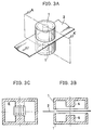
- Fig.lA shows a typical apparatus of the present invention for measuring physical quantities of sheet material.
- a cylindrical re-entrant cavity resonator 1 which is axially symmetrical, is provided with emitting means and receiving means of microwave not shown in the figure. This shows that moisture content of paper in the paper process production is being measured in on-line manner.
- Object 2 to be measured can be any kinds of sheet materials such as grains, various materials of fluid particulate e.g. for forming ceramic, stringy materials, corrugated fiberboard material, various laminate coated like a film base, etc. Even if the object is particulate or fluid, it can be measured as long as it can be converted into a sheet-like shape. Since the object 2 to be measured is inserted into the gap between lower portion of resonator 3 and cavity resonator 1 without contact, measurement can be conducted in non-contact and on-line manner.
- Fig.lB shows a longitudinal section view taken on line A-A' of Fig.lA for explaining the structure of the apparatus in Fig.lA.
- Fig.lB shows that protrusion 4 faces the paper 2 which is the object.
- strong electric fields emitting from the vicinity of the top portion in protrusion 4 distribute vertically against the object.
- the portion to be measured is confined to the area which is almost the same as one of the top portion of the protrusion, so that the moisture content of the minute area of the object can be measured.
- the cavity resonator of an embodiment made of aluminum, whose outer and inner radii are 2.54 cm and 0.9 cm respectively, has a cavity length of 2.99 cm.
- the resonance frequency of 2.9 GH and the Q-value of 7097 are obtained experimentally. It is found that those values are in good agreement with the calculated ones. And it should be noted that the full width at half maximum is only 380 kHz at the resonant freaquency of 2.9 G H , which is extremely narrow. This means that a high Q-value can be obtained by the apparatus of the present invention.
- the Q-value is about 5500 and the half band width is as broad as 700 kHz. It can be said that the resonator of the present invention has a greater sensitivity than the conventional one.
- Another advantage of the apparatus of the invention is that the configuration formed by two electrodes of the cavity resonator does not change even if the concave cylindrical cavity resonator 1 moves horizontally at the time of measuring, because the lower part 3 of the resonator is flat. Therefore stable measurement can be attained.
- the apparatus is easy to manufacture because it is axial symmetry and cylindrical.
- Fig.2A is a modified example of the apparatus shown in Fig.1 for measuring physical quantities.
- Fig.2B is a cross section taken on line A-A' of Fig.2B and Fig.2C shows the measurement principle of the apparatus.
- upper cylindrical cavity resonator 5 and lower cylindrical cavity resonator 6 are faced, and the object 2 to be measured, such as paper, is inserted between them.
- Upper and lower cylinders have respectively a protrusion 4 provided with a penetrating hole, as shown in a cross section of Fig.2B, whose holes in the protrusions are precisely lined up between both resonators.
- Fig.2C shows that the distribution of electric field is dense at the vicinity of the top portion of said protrusion and is vertical against the object.
- Upper and lower cylindrical cavity resonators do not necessarily have the same shape. It is only necessary that its shape gives rise to the electric field distribution at the vicinity of the top portion in the protrusion as shown in Fig.2C.
- Fig.3A is another modified example of the apparatus of Fig.1 for measuring physical quantities.
- Fig.3B is a cross section taken on line A-A' of Fig.3A
- Fig.3C is a drawing to show the principle thereof.
- the apparatus corresponds to the one in which the hole in the apparatus of Fig.2A is filled up. It can be said that the system comprises two same re-entrant cavities shown in Fig.1C.
- Fig.3C shows that electric field in the cavity resonator is extremely strong at the vicinity of the protrusion and is vertical against the object.
- Upper and lower re-entrant resonators do not necessarily have the same shape as in the cases mentioned above.
- any kind of cavity resonator where a protrusion is provided on the area corresponding to the part to be measured, so that electric field distribution becomes dense for the object, can be accepted as the apparatus of the present invention for measuring physical quantities of sheet-like material.
- the cavity resonator of the present invention is not limited to the one made of metal, such as aluminum. It can be the cavity resonator whose body is made of plastics, and whose inside surface is coated with conductive material ,such as Al or Ag, so as to decrease the weight of the resonator.
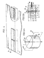
- each cavity block of about 1m in length, has six re-entrant type cavity resonators.
- Each cavity resonator in the cavity block made of Al, has a cylindrical protrusions.
- Upper plate 8 faced to cavity part 7 is a plate of 1m which is common to six microwave cavity resonators.
- each block of 1m in length is provided with a microwave transmitter can be accepted.
- This system enables to apply commonly microwave to each cavity resonator in a block for microwave measurement so that only one microwave transmitter is enough for one block, which results in reduced costs of the measuring system.
- Fig.5A is a perspective view of cylindrical cavity resonator 1 of the present invention that is suitable for measuring of quantities of stringy materials.
- the cylindrical cavity resonator 1 is made of Al, and provided with an emitting and receiving means 16 of microwave. Reflected microwave is received by the emitting and receiving means of microwave 16.
- the object 2 to be measured is a shape like pipe, rod and fiber. In the embodiment shown in Fig.5, the object 2 to be measured is 0.2mm diameter glass fiber containing minute metal pieces. The physical quantities of the object 2 is obtained from the comparison between the resonance characteristics of the glass fiber with metal pieces and the one of glass fiber without metal pieces.
- protrusion 4 is provided on the center of cylindrical cavity resonator 1, and space 17 is provided on the center of the protrusion 4 for placing the object, which enables measurement in non-contact and on-line manner.
- outside diameter b of the cavity is 60 mm; inside diameter c is 42 mm; the height e of the cavity is 38 mm; inside height d is 25 mm; the diameter g of the protrusion is 42 mm; the distance a between the upper edge of the cavity and the top of the protrusion is 16.1 mm; the inside diameter of space 17 is 3.2 mm.
- D/A converter 19 converts directing signal from CPU 18 into analog signals which are put into VCO 20 and x axis of x-y recorder 15. Microwave generated at VCO 20 is applied to y axis of x-y recorder 15 through detector 13 and amplifier 14 for recording the resonance characteristic of each object 2 to be measured.
- cylindrical cavity resonator 1 of the present invention for stringy materials is not restricted to the one shown in Fig.5B. Available are the one that a hole is not provided on the bottom plate as shown in Fig.10, or the one that protrusions are provided on both ends as shown in Fig.ll.
- the cavity resonator 1 of the present invention is not necessarily made of metal, such as Aluminum. It can be one wholly made of plastics the inside surface of which is coated with conductive material, such as Al and Ag, in order to decrease its weight.
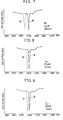
- Fig.9 shows the result of the measured resonance frequency when grass fibers of 0.2mm ⁇ , containing Ni pieces of 4mmo in diameter and 20mm in length, are inserted into the space 17 of circular cavity resonator 1 as shown in Fig.5.
- Curve a shows the reflection characteristics of glass fiber of 0.2mmo without Ni pieces, and curve b does that containing Ni pieces.
- Fig.7 it can be found that the resonation frequency of curb b is displaced by 25MH z with reference to curb a, because of the existence of minute Ni pieces. This concludes that the measurement apparatus for physical quantities of this invention can detect minute Ni pieces with extremely great sensitivity.
- Fig.8 shows the result of measured resonance frequency of glass fiber of 0.2mm ⁇ , containing Au pieces of 25mmo in diameter and 5mm in length, and one of the same glass fiber without Au pieces. This example also shows that the measuring apparatus of the invention can definitely detect the existence of Au pieces.
- Fig.9 shows the result of measured resonance frequency of glass fiber of 0.2mm ⁇ , containing Cu pieces of 10mm ⁇ in diameter and 5mm in length, and one of the same glass fiber without Cu pieces.
- the object was paper.
- the moisture content and basis weight were mersured by a conventional method for 1500 samples which had been kept in a thermostatic chamber. They were obtained from 30 pieces of paper whose moisture content was in the range of 3%-13% and 50 pieces of paper whose basis weight was in the range of 10g/m 2 -800g/m 2 .
- the frequency f and voltage v of maximum resonance of microwave were measured on said 1,500 samples and 3,000 measured data were obtained.
Landscapes
- Physics & Mathematics (AREA)
- General Physics & Mathematics (AREA)
- Electromagnetism (AREA)
- Analytical Chemistry (AREA)
- Life Sciences & Earth Sciences (AREA)
- Chemical & Material Sciences (AREA)
- Health & Medical Sciences (AREA)
- Biochemistry (AREA)
- General Health & Medical Sciences (AREA)
- Immunology (AREA)
- Pathology (AREA)
- Investigating Or Analyzing Materials By The Use Of Electric Means (AREA)
- Measurement Of Resistance Or Impedance (AREA)
- Control Of Motors That Do Not Use Commutators (AREA)
- Details Of Audible-Bandwidth Transducers (AREA)
Abstract
An apparatus for measuring physical quantities consists of a microwave cavity resonator (1) of the structure provided with a protrusion (4) on the central axis thereof. A material (2) to be measured is placed on a central portion (17) of the protrusion (4) in parallel therewith or is placed perpendicularly to the protrusion (4), so that the electric field is concentrated in the area where measurement is to be taken. This makes it possible to correctly measure the physical quantities for a tiny portion in the area where measurement is to be taken. According to a method of measuring physical quantities, the frequency and voltage are measured at a maximum resonance point of microwaves of the material that is to be measured, and a moisture content x and a basis weight y are calculated from a characteristic equation that includes at least the term of product of the moisture content x and basis weight y. This makes it possible to easily and correctly calculate the moisture content and basis weight.
Description
- The present invention relates to an apparatus and a method for measuring physical or chemical properties of materials by absorption quantities of microwave energy or a shift in resonant frequency of a cavity.
- The technology of measuring moisture content of paper and others, by means of microwave in on-line manner in the paper-production process, has been noticed recently. It is desirable that these contents can be always measured and feedbacked, in on-line manner, to the process of adjusting or drying raw material of pulp in order to maintain the good quality of finished paper. In addition, a paper price is determined by a paper weight per unit area on taking delivery from a factory. Then it is tried to make the paper contain the moisture content as much as possible without detoriorating its quality. Therefore measuring the moisture content accurately on-line is one of very important subjects in not only paper-production processes but also many other technical fields. As shown in Japanese Patent Publication No.58-30354, the prior method of measuring moisture content of the object is to measure a difference in microwave energy and a shift in a resonant frequency between cases when a sheet object is inserted, and when not inserted, in a gap formed between an upper rectangular prism provided with means for emitting microwave and a lower one provided with means for emmitting it.
- Each of upper and lower typical rectangular prisms of cavity resonators in the prior method has an opening cross-section of about 30cm x 60cm, a depth of about 70cm. An intermediate gap formed between an upper one and a lower one is about lcm. Since 3GHz is primarily used for microwave oscillators including circuits which are commercially available, these dimensions of the cavity and this gap width have been adopted in order to be fitted to the frequency.
- There are four problems in measuring moisture content by means of the conventional rectangular prism cavity resonator when manufacturing paper.
- The first problem is that the opening of the resonator can not be smaller than 30cm x 60cm. It is necessary to measure moisture content in the area as small as possible in practice. In the production of paper, especially, it is the most important to adjust the moisture content contained in the width of about 10cm from edge of the paper to an adequate value. However it has been very difficult to make such measurement by using the conventional technique.
- The second problem is that because the conventional cavity shaped like a rectangular prism has low Q-value, Q-value and resonant frequency of microwave do not vary sensitively when the object is inserted or even when its moisture content varies. Therefore the accuracy of measurement has been extremely poor.
- The third problem is that if the upper and lower cavity resonators with same dimension are displaced each other along the plane of a sheet object in the case of on-line measurement, the required measurement, then, can not be conducted. Because, in that case, the cavity resonator does not function properly even if the dislocation is small. Therefore it extremely harms the stability of on-line measurement in the production of the objects such as paper.
- The fourth problem is the difficulty of realizing an accurate rectangular prism shape in practice because the demand of accuracy for dimensions of the cavity resonator is very severe. In case of constructing an accurate rectangular prism cavity by pasting plate members together, it is difficult to keep the parrallelism at the position where the members are placed together. As a result, in practice, preventing the energy loss of microwave induced by the pseudomorphic cavity becomes hard. In other words, it is difficult to make the cavity of a precise configuration having Q-value similar to a theoretical value.
- Typical prior method for the measurement of moisture content is based upon empirical determination of proportional constants on the assumption that the maximum resonant voltage V of microwave is proportional only to moisture content in the paper inserted in the gap formed between two cavities. Even slight changes in measurement environment, such as temperature or moisture, extremely affect the measuring results of moisture content. Thus this kind of conventional method needs calibration curves for each apparatus which are difficult to handle, very complicated, and dependent on skill and experience. As a result, the measurement accuracy varies from several % to over 5% in the effective measurement range of 3-13 % when measuring moisture content, so that one will find little reliability, reproductivity and stability in measurement.
- On the other hand, a microwave cavity resonator has never been used for the measuring of paper weight (mass per unit area). β rays, being dangerous to use, have been adopted to measure it in the paper-production processes. The accuracy of the paper weight using 0 radiation varies by 3g/m2 in an effective measurement range of 10g/m2-800g/m2, which leads to unsatisfied accuracy.
- The object of the present invention is to provide a microwave re-entrant cavity resonator which enables the accurate measurement of physical quantities in minute portion of sheet materials.
- Another object of the present invention is to provide a microwave re-entrant cavity resonator which enables the precise measurement of physical quantities of stringy materials.
- Still another object of the present invention is to provide the method for the precise measurement of moisture content and the weight of object by means of a microwave cavity resonator.
- According to the invention, there is provided a microwave cavity resonator having a pair of electrodes whose upper one is provided with means for emitting microwave signals and whose lower one is provided with means for receiving them, characterized in that a protruding portion is provided on the part corresponding to at least one of the electrodes. According to this configuration, the distribution of electric field density of microwave which is irradiated to the object, can be greatly increased at the vicinity of the protruding portion. As a result, the area to be measured can be confined to the same area as the protruding portion, and at the same time, changes in Q-value and resonant frequency obtained from a cavity resonator can be made sensitive.
- According to the invention, there is provided another apparatus for measuring physical quantities comprising a cylindrical microwave cavity resonator equipped with emitting means and receiving means of microwave on the side, characterized in that a penerated hole is provided in the center of said protruding portion for holding the object. By this configuration, stringy materials can be placed on the region where the electric field is the largest, so that the physical quantities can be measured precisely.
- The invention provides a method of measuring moisture content x and weight y of the sheet material by using a microwave cavity resonator, characterized that after every proportional constant in the following characteristic equation having at least product term xy


- This measuring method acheives a great improvement in measurement accuracy of moisture content and weight.
-
- Fig.lA is an apparatus of measuring physical quantities of the invention; Fig.lB is a section view taken on line A-A' of Fig.lA and Fig.1C is a drawing to show the principle of the apparatus of the invention.
- Fig.2A is a perspective view of a modified example of the apparatus of Fig.1; Fig.2B is a section view taken on line A-A' of Fig.2B and Fig.2C is a drawing to show the principle thereof.
- Fig.3A is a perspective view of another example of the apparatus of Fig.1; Fig.3B is a section view taken on line A-A' of Fig.3A and Fig.3C is a drawing to show the principle thereof.
- Fig.4 shows the second embodyment of the present invention.
- Fig.5A is a perspective view of the apparatus of the second present invention, and Fig.5B is a section view taken on line B-B' of Fig.5A.
- Fig.6 shows a circuit diagram used for the apparatus of the invention.
- Figs.7-9 show measurement results obtained by the apparatus of Figs.5A and B.
- Figs.10 and 11 show modified example of the apparatus of the present second invention.
- Fig.lA shows a typical apparatus of the present invention for measuring physical quantities of sheet material. A cylindrical
re-entrant cavity resonator 1 which is axially symmetrical, is provided with emitting means and receiving means of microwave not shown in the figure. This shows that moisture content of paper in the paper process production is being measured in on-line manner.Object 2 to be measured can be any kinds of sheet materials such as grains, various materials of fluid particulate e.g. for forming ceramic, stringy materials, corrugated fiberboard material, various laminate coated like a film base, etc. Even if the object is particulate or fluid, it can be measured as long as it can be converted into a sheet-like shape. Since theobject 2 to be measured is inserted into the gap between lower portion ofresonator 3 andcavity resonator 1 without contact, measurement can be conducted in non-contact and on-line manner. - Fig.lB shows a longitudinal section view taken on line A-A' of Fig.lA for explaining the structure of the apparatus in Fig.lA. Fig.lB shows that
protrusion 4 faces thepaper 2 which is the object. As shown in Fig.1C, strong electric fields emitting from the vicinity of the top portion inprotrusion 4 distribute vertically against the object. Thus, the portion to be measured is confined to the area which is almost the same as one of the top portion of the protrusion, so that the moisture content of the minute area of the object can be measured. The cavity resonator of an embodiment made of aluminum, whose outer and inner radii are 2.54 cm and 0.9 cm respectively, has a cavity length of 2.99 cm. When the separation between the top of theprotrusion 4 andlower part 3 of the cavity is 1.35 cm, the resonance frequency of 2.9 GH and the Q-value of 7097 are obtained experimentally. It is found that those values are in good agreement with the calculated ones. And it should be noted that the full width at half maximum is only 380 kHz at the resonant freaquency of 2.9GH , which is extremely narrow. This means that a high Q-value can be obtained by the apparatus of the present invention. In the conventional rectangular prism cavity resonator having a resonant frequency of 2.9 GH , the Q-value is about 5500 and the half band width is as broad as 700 kHz. It can be said that the resonator of the present invention has a greater sensitivity than the conventional one. - Another advantage of the apparatus of the invention is that the configuration formed by two electrodes of the cavity resonator does not change even if the concave
cylindrical cavity resonator 1 moves horizontally at the time of measuring, because thelower part 3 of the resonator is flat. Therefore stable measurement can be attained. In addition, the apparatus is easy to manufacture because it is axial symmetry and cylindrical. - Fig.2A is a modified example of the apparatus shown in Fig.1 for measuring physical quantities. Fig.2B is a cross section taken on line A-A' of Fig.2B and Fig.2C shows the measurement principle of the apparatus. In Figs.2A and 2B, upper
cylindrical cavity resonator 5 and lowercylindrical cavity resonator 6 are faced, and theobject 2 to be measured, such as paper, is inserted between them. Upper and lower cylinders have respectively aprotrusion 4 provided with a penetrating hole, as shown in a cross section of Fig.2B, whose holes in the protrusions are precisely lined up between both resonators. Fig.2C shows that the distribution of electric field is dense at the vicinity of the top portion of said protrusion and is vertical against the object. Upper and lower cylindrical cavity resonators do not necessarily have the same shape. It is only necessary that its shape gives rise to the electric field distribution at the vicinity of the top portion in the protrusion as shown in Fig.2C. - Fig.3A is another modified example of the apparatus of Fig.1 for measuring physical quantities. Fig.3B is a cross section taken on line A-A' of Fig.3A, and Fig.3C is a drawing to show the principle thereof. The apparatus corresponds to the one in which the hole in the apparatus of Fig.2A is filled up. It can be said that the system comprises two same re-entrant cavities shown in Fig.1C. Fig.3C shows that electric field in the cavity resonator is extremely strong at the vicinity of the protrusion and is vertical against the object. Upper and lower re-entrant resonators do not necessarily have the same shape as in the cases mentioned above.
- As described above, any kind of cavity resonator where a protrusion is provided on the area corresponding to the part to be measured, so that electric field distribution becomes dense for the object, can be accepted as the apparatus of the present invention for measuring physical quantities of sheet-like material.
- The cavity resonator of the present invention is not limited to the one made of metal, such as aluminum. It can be the cavity resonator whose body is made of plastics, and whose inside surface is coated with conductive material ,such as Al or Ag, so as to decrease the weight of the resonator.
- In the system of the present invention for measuring physical quantities shown in Fig.4, many cavity blocks are placed in line in the whole region of the object, wherein each cavity block, of about 1m in length, has six re-entrant type cavity resonators. Each cavity resonator in the cavity block, made of Al, has a cylindrical protrusions.
Upper plate 8 faced to cavity part 7 is a plate of 1m which is common to six microwave cavity resonators. By the reason of this configuration where many cavity blocks are placed, one can measure the physical quantities of the whole object without the necessity of moving a cavity resonator in the whole region of the object in case in which only one cavity resonator is provided for the whole region. - In the system for measuring physical quantities shown in Fig.4, emitting part of microwave is not shown, but as one of examples, the system such that each block of 1m in length is provided with a microwave transmitter can be accepted. This system enables to apply commonly microwave to each cavity resonator in a block for microwave measurement so that only one microwave transmitter is enough for one block, which results in reduced costs of the measuring system.
- Fig.5A is a perspective view of
cylindrical cavity resonator 1 of the present invention that is suitable for measuring of quantities of stringy materials. Thecylindrical cavity resonator 1 is made of Al, and provided with an emitting and receiving means 16 of microwave. Reflected microwave is received by the emitting and receiving means ofmicrowave 16. Theobject 2 to be measured is a shape like pipe, rod and fiber. In the embodiment shown in Fig.5, theobject 2 to be measured is 0.2mm diameter glass fiber containing minute metal pieces. The physical quantities of theobject 2 is obtained from the comparison between the resonance characteristics of the glass fiber with metal pieces and the one of glass fiber without metal pieces. As shown in a cross section view of Fig.5B taken on line B-B' of Fig.5B,protrusion 4 is provided on the center ofcylindrical cavity resonator 1, andspace 17 is provided on the center of theprotrusion 4 for placing the object, which enables measurement in non-contact and on-line manner. - Concerning dimensions of every portion of
cylindrical cavity resonator 1 shown in Fig.5, outside diameter b of the cavity is 60 mm; inside diameter c is 42 mm; the height e of the cavity is 38 mm; inside height d is 25 mm; the diameter g of the protrusion is 42 mm; the distance a between the upper edge of the cavity and the top of the protrusion is 16.1 mm; the inside diameter ofspace 17 is 3.2 mm. - Circuit configuration used for an apparatus of the present invention for measuring quantities will be explained based on Fig.6. D/
A converter 19 converts directing signal fromCPU 18 into analog signals which are put intoVCO 20 and x axis ofx-y recorder 15. Microwave generated atVCO 20 is applied to y axis ofx-y recorder 15 through detector 13 and amplifier 14 for recording the resonance characteristic of eachobject 2 to be measured. - The configuration of
cylindrical cavity resonator 1 of the present invention for stringy materials is not restricted to the one shown in Fig.5B. Available are the one that a hole is not provided on the bottom plate as shown in Fig.10, or the one that protrusions are provided on both ends as shown in Fig.ll. - The
cavity resonator 1 of the present invention is not necessarily made of metal, such as Aluminum. It can be one wholly made of plastics the inside surface of which is coated with conductive material, such as Al and Ag, in order to decrease its weight. - Due to the confinement effect of electricity to the space of the protrusion electrode inside the cavity, as the above-mentioned localization effect, Q value and resonating frequency of the cavity change with great responsiveness depending on a slight change in physical quantities of objects to be measured. Thus not only pipe-shape, rod-shape or stringy materials themselves but also minute metal pieces contained in them can be measured precisely.
- Fig.9 shows the result of the measured resonance frequency when grass fibers of 0.2mmØ, containing Ni pieces of 4mmo in diameter and 20mm in length, are inserted into the
space 17 ofcircular cavity resonator 1 as shown in Fig.5. Curve a shows the reflection characteristics of glass fiber of 0.2mmo without Ni pieces, and curve b does that containing Ni pieces. According to Fig.7, it can be found that the resonation frequency of curb b is displaced by 25MHz with reference to curb a, because of the existence of minute Ni pieces. This concludes that the measurement apparatus for physical quantities of this invention can detect minute Ni pieces with extremely great sensitivity. - Fig.8 shows the result of measured resonance frequency of glass fiber of 0.2mmØ, containing Au pieces of 25mmo in diameter and 5mm in length, and one of the same glass fiber without Au pieces. This example also shows that the measuring apparatus of the invention can definitely detect the existence of Au pieces.
- Fig.9 shows the result of measured resonance frequency of glass fiber of 0.2mmØ, containing Cu pieces of 10mm∅ in diameter and 5mm in length, and one of the same glass fiber without Cu pieces.
- Finally, the method of measuring of this invention using a microwave cavity resonator, which makes it easy to measure the physical quantities of the objects to be measured, will be explained.
- A pair of rectangular prism cavity resonators in which two cavities with an opening of 34 x 76mm and a depth of 10mm were placed to form a gap of 10mm, were employed for measurement using 3GH . The object was paper. At first,the moisture content and basis weight were mersured by a conventional method for 1500 samples which had been kept in a thermostatic chamber. They were obtained from 30 pieces of paper whose moisture content was in the range of 3%-13% and 50 pieces of paper whose basis weight was in the range of 10g/m2-800g/m2. Secondly, the frequency f and voltage v of maximum resonance of microwave were measured on said 1,500 samples and 3,000 measured data were obtained. Considering the dependency of moisture content x and basis weight y on f and v depending on those data, concluded that the moisture content x and basis weight y determined from the following equations do not differ from the true values, as long as lst order terms and cross terms are taken into account.


- In case of paper measurement, it is not necessary to consider the terms of higher than second order. By using said 3,000 data, proportional constants were decided as follows:


- It was already mentioned that the resonance voltage v is eminently affected by the phenomena that water absorbs microwave, but the above equations reflect this phenomena. In addition, they apparently represent other factors which could not be predicted quantitatively beforehand.
- It is assured to measure moisture content with accuracy 0.3g/m2 in the effective measuring range 3%-13%. Concerning basis weight, the accuracy of 0.3g/m2 was obtained in the range of 10g/m2. In both cases, measurement was scarecely affected by mesurement environment.
- Although this embodiment was explained with rectangular prism cavity resonators used in the prior art, it is nothing to say that the measuring method of the present invention is not confined to the method using it. The measuring apparatus of the present invention shown in Figures 1,2,3,4,5,6,10 and 11 can be also applied to the measuring method of the present invention.
Claims (11)
1. An apparatus for measuring physical quantities of sheet object having a pair of electrodes with a microwave emitting and receiving means which are placed on both sides of the sheet object to be measured, characterized in that a protrusion is provided on the area to be measured corresponding to at least one of the electrodes.
2. The apparatus for measuring physical quantities as set forth in claim 1, characterized in that the electrode provided with the protrusion is cylindrical.
3. The apparatus for measuring physical quantities as set forth in claim 1 or 2, characterized in that the electrode faced to the electrode provided with the protrusion is a plate.
4. The apparatus for measuring physical quantities as set forth in claim 1, 2 or 3, characterized in that the electrode is made of plastics coated with metal.
5. A system for measuring physical quantities comprising a plurality of fixed apparatus for measuring physical quantities as set forth in any one of claims 1-4, wherein simultaneous measurement on a plurality of portions to be measured can be conducted.
6. An apparatus for measuring physical quantities comprising a cylindrical microwave cavity resonator which has a microwave emitting and receiving means on its side wall and has a protrusion on its axis, characterized in that a penetrating space for placing the object to be measured is provided on the central portion of the protrusion.
7. The apparatus for measuring physical quantities as set forth in claim 6, characterized in that a hole is provided on a wall faced to the penetrating space of the protrusion.
8. The apparatus for measuring physical quantities as set forth in claim 6, characterized in that a hole is not provided on a wall faced to the penetrating space of the protrusion.
9. The apparatus for measuring physical quantities as set forth in claim 6, characterized in that two protrusions are faced on its common axis.
10. The apparatus for measuring physical quantities as set forth in any one of claims 6-9, characterized in that the cavity resonator is made of plastics whose inside surface is coated with metal.
11. A method of measuring moisture content x and basis weight y of sheet object to be measured using a microwave cavity resonator characterized by measuring frequency f and voltage v at the maximum resonance point of microwave on samples whose moisture content x and basis weight y are previously obtained, determining every proportional constants of the following equations including at least product terms of x and y 

then, calculating moisture content x and basis weight y by the equations using measured values of frequency f and voltage v of the object to be measured.
Applications Claiming Priority (2)
| Application Number | Priority Date | Filing Date | Title |
|---|---|---|---|
| JP293026/86 | 1986-12-09 | ||
| JP61293026A JPS63145951A (en) | 1986-12-09 | 1986-12-09 | Physical quantity measuring apparatus |
Publications (2)
| Publication Number | Publication Date |
|---|---|
| EP0292571A1 true EP0292571A1 (en) | 1988-11-30 |
| EP0292571A4 EP0292571A4 (en) | 1989-10-04 |
Family
ID=17789524
Family Applications (1)
| Application Number | Title | Priority Date | Filing Date |
|---|---|---|---|
| EP19870907989 Withdrawn EP0292571A4 (en) | 1986-12-09 | 1987-12-08 | Apparatus for measuring physical quantities and a method therefor. |
Country Status (4)
| Country | Link |
|---|---|
| US (1) | US4890054A (en) |
| EP (1) | EP0292571A4 (en) |
| JP (1) | JPS63145951A (en) |
| WO (1) | WO1988004423A1 (en) |
Cited By (16)
| Publication number | Priority date | Publication date | Assignee | Title |
|---|---|---|---|---|
| EP0509187A1 (en) * | 1991-04-18 | 1992-10-21 | Barco Automation, Naamloze Vennootschap | Method for determining the mass of a soft product moving in a measuring device |
| EP0468057A4 (en) * | 1990-02-05 | 1992-11-19 | Dipole Electronics Co. Ltd. | Detector for conductive substance mixed in string-like material |
| ES2047438A2 (en) * | 1992-03-04 | 1994-02-16 | Univ Zaragoza | Device for automatic control of selection and changing of scales of a stationary wave meter |
| GB2277803A (en) * | 1993-05-05 | 1994-11-09 | Jerry Geoffrey Assenheim | Microwave moisture determination |
| EP0889321A1 (en) * | 1997-07-02 | 1999-01-07 | TEWS ELEKTRONIK Dipl.-Ing. Manfred Tews | Moisture and density sensor |
| EP0758085A3 (en) * | 1995-08-08 | 1999-09-01 | Appleton Mills | Moisture detection apparatus and methods |
| EP1004874A1 (en) * | 1998-11-26 | 2000-05-31 | Hauni Maschinenbau AG | Resonator housing for micro waves |
| EP0753755A3 (en) * | 1995-07-14 | 2000-07-12 | Hauni Maschinenbau Aktiengesellschaft | Device for the measurement of the complex dielectric constant of tobacco |
| EP0967479A3 (en) * | 1998-06-25 | 2002-11-27 | Allen-Bradley Company, LLC | Method and apparatus for measuring the density of a substance having free water compensation |
| WO2008015553A3 (en) * | 2006-08-03 | 2008-07-10 | Gd Spa | A re-entrant microwave resonator for detecting a characteristic like humidity, density or presence of foreign substances in a fibrous material like |
| DE202006020481U1 (en) | 2006-05-09 | 2008-08-21 | Ams Advanced Microwave Systems Gmbh | Microwave measuring device for determining at least one measured variable on a product |
| US7759947B2 (en) | 2006-12-15 | 2010-07-20 | Voith Patent Gmbh | Method and apparatus for determining the moisture of a running material web |
| DE102011083051A1 (en) * | 2011-09-20 | 2013-03-21 | Hauni Maschinenbau Ag | Mikrowellenresonatorgehäuse |
| CN107655902A (en) * | 2017-08-25 | 2018-02-02 | 天津大学 | A kind of circular microwave resonant cavity sensor solution concentration measuring method |
| EP2848133B1 (en) | 2013-07-16 | 2018-05-30 | Hauni Maschinenbau GmbH | Assembly and method for checking rod-shaped articles from the tobacco processing industry |
| EP3158325B1 (en) | 2014-06-17 | 2020-04-01 | Hauni Maschinenbau GmbH | Microwave measuring device, arrangement and method for the verification of rod-shaped articles or of a rod of material of the tobacco processing industry and machine of the tobacco processing industry |
Families Citing this family (34)
| Publication number | Priority date | Publication date | Assignee | Title |
|---|---|---|---|---|
| JPS63210757A (en) * | 1987-02-27 | 1988-09-01 | Nippon Glass Fiber Co Ltd | Device and method for detecting conductive material in nonconductive fiber |
| JPH01172738A (en) * | 1987-12-28 | 1989-07-07 | Asahi Fiber Glass Co Ltd | Detecting method for dielectric |
| AU614904B2 (en) * | 1989-07-31 | 1991-09-12 | American Telephone And Telegraph Company | Measuring and controlling the thickness of a coating on a elongated article |
| FR2661500B1 (en) * | 1990-04-25 | 1994-01-07 | Aerospatiale Ste Nationale Indle | MICROWAVE CAVITY SUITABLE FOR MEASURING THE ELECTROMAGNETIC CHARACTERISTICS OF A FILIFORMED MATERIAL IN PROGRESS. |
| GB9121678D0 (en) * | 1991-10-12 | 1991-11-27 | Unaform Ltd | Microwave drainage meter |
| DE4211362C2 (en) * | 1992-04-04 | 1995-04-20 | Berthold Lab Prof Dr | Device for determining material parameters by microwave measurements |
| GB2294326A (en) * | 1994-10-06 | 1996-04-24 | Scapa Group Plc | Moisture detection meter |
| US5666061A (en) * | 1994-11-09 | 1997-09-09 | James Instruments Inc. | Apparatus and method for measurement of moisture concentration in granular materials |
| US5594351A (en) * | 1995-05-23 | 1997-01-14 | The United States Of America As Represented By The Administrator Of The National Aeronautics And Space Administration | Apparatus for use in determining surface conductivity at microwave frequencies |
| US5838158A (en) * | 1995-08-08 | 1998-11-17 | Appleton Mills | Measuring system for measuring the amount of dielectric in a web |
| EP0853707A1 (en) * | 1995-10-05 | 1998-07-22 | Minnesota Mining And Manufacturing Company | Flexible raised pavement marker, mounting device and method |
| US5714697A (en) * | 1996-06-19 | 1998-02-03 | Xerox Corporation | Sheet materials mass measuring system |
| US6445191B1 (en) | 1997-07-31 | 2002-09-03 | Mikrowellen-Technologie Und Sensoren Gmbh | Distance measuring device and method for determining a distance |
| DE19734713A1 (en) | 1997-08-11 | 1999-02-18 | Mikrowellen Technologie Und Se | Radar range finder |
| DE29716639U1 (en) * | 1997-09-16 | 1999-01-21 | Tews Elektronik, 22459 Hamburg | Microwave stray field sensor for moisture and / or density measurement |
| ATE288581T1 (en) | 1998-08-31 | 2005-02-15 | Malcam Ltd | MICROWAVE RESONATOR FOR CONTINUOUS EVALUATION OF FIBER MATERIALS |
| ATE326684T1 (en) * | 2000-06-27 | 2006-06-15 | Univ Catholique Louvain | MEASURING CYLINDRICAL OBJECTS USING LASER TELEMETRY |
| US6467977B2 (en) * | 2000-12-19 | 2002-10-22 | Hewlett-Packard Company | Media weight sensor using a resonant piezoelectric element |
| US6485205B2 (en) * | 2000-12-19 | 2002-11-26 | Hewlett-Packard Company | Media weight sensor using an acoustic resonator |
| DE10112499B4 (en) | 2001-03-15 | 2010-08-19 | Hauni Maschinenbau Ag | Resonator device, in particular Mikrowellenresonatoreinrichtung |
| EP1655601A4 (en) * | 2003-07-31 | 2008-01-23 | Oji Paper Co | METHOD AND DEVICE FOR MEASURING A MOISTURE CONTENT |
| DE202005001756U1 (en) * | 2004-02-12 | 2005-05-04 | Trützschler GmbH & Co KG | Microwave sensor for measuring a dielectric property of a product |
| US20060208194A1 (en) * | 2005-03-18 | 2006-09-21 | Voith Paper Patent Gmbh | Microwave mass measuring device and process |
| WO2007130896A2 (en) * | 2006-05-01 | 2007-11-15 | Massachusetts Institute Of Technology | Microwave sensing for determination of loading of filters |
| FI121195B (en) * | 2006-06-22 | 2010-08-13 | Senfit Oy | Method and instrument for radio wave measurement |
| US7570136B2 (en) * | 2006-09-20 | 2009-08-04 | Alcatel-Lucent Usa Inc. | Re-entrant resonant cavities, filters including such cavities and method of manufacture |
| US8324989B2 (en) * | 2006-09-20 | 2012-12-04 | Alcatel Lucent | Re-entrant resonant cavities and method of manufacturing such cavities |
| DE102006051577B4 (en) * | 2006-11-03 | 2011-07-21 | Deutsche Solar AG, 09599 | Apparatus and method for detecting electrical properties of a sample of a stimulable material |
| DE102007025815A1 (en) * | 2007-06-02 | 2008-12-04 | Voith Patent Gmbh | Method and device for measuring at least one quality size of a fibrous web |
| DE102010063232A1 (en) * | 2010-12-16 | 2012-06-21 | Voith Patent Gmbh | Apparatus and method for basis weight determination |
| JP6017126B2 (en) * | 2011-09-27 | 2016-10-26 | 旭化成エンジニアリング株式会社 | Foreign matter detection method and foreign matter detection device |
| WO2015199077A1 (en) * | 2014-06-25 | 2015-12-30 | 宇部興産株式会社 | Dielectric contactless transmission device and contactless transmission method |
| RU2579359C1 (en) * | 2015-02-05 | 2016-04-10 | Федеральное государственное бюджетное учреждение науки Институт проблем управления им. В.А. Трапезникова РАН | Method of measuring physical quantity |
| DE102015206650A1 (en) * | 2015-04-14 | 2016-10-20 | Bhs Corrugated Maschinen- Und Anlagenbau Gmbh | Plant for producing a corrugated web |
Family Cites Families (14)
| Publication number | Priority date | Publication date | Assignee | Title |
|---|---|---|---|---|
| US3079551A (en) * | 1958-01-23 | 1963-02-26 | Beloit Iron Works | Apparatus and method for measurement of moisture content |
| SU398896A1 (en) * | 1972-04-18 | 1973-09-27 | Н. И. Матушкин , Д. П. Буртовой Харьковский институт радиоэлектроники | DEVICE FOR MEASUREMENT OF ELECTRIC |
| US4095475A (en) * | 1976-04-22 | 1978-06-20 | Massachusetts Institute Of Technology | Apparatus and method whereby wave energy is correlated with geometry of a manufactured part or the like or to positional relationships in a system |
| DE2907964C2 (en) * | 1979-03-01 | 1981-02-26 | Hermann Berstorff Maschinenbau Gmbh, 3000 Hannover | Method for testing the dielectric heatability and device for carrying out the method |
| JPS5830534A (en) * | 1981-08-18 | 1983-02-23 | Mitsubishi Electric Corp | Magnetic particle type electromagnetic coupling device |
| JPS59197843A (en) * | 1983-04-26 | 1984-11-09 | Yokogawa Hokushin Electric Corp | Microwave moisture meter |
| JPS59224547A (en) * | 1983-06-03 | 1984-12-17 | Kanzaki Paper Mfg Co Ltd | Measuring method of fiber orientation of fiber sheet |
| JPS6020138A (en) * | 1983-07-14 | 1985-02-01 | Nippon Electric Glass Co Ltd | Method for detecting defect of glass fiber |
| US4600879A (en) * | 1984-06-15 | 1986-07-15 | Scully John P | Water moisture measuring instrument and method |
| JPS6183946A (en) * | 1984-10-01 | 1986-04-28 | Kanzaki Paper Mfg Co Ltd | Orientation measurement method for sheet material |
| JPH0540568Y2 (en) * | 1985-08-26 | 1993-10-14 | ||
| JPH0658331B2 (en) * | 1985-11-26 | 1994-08-03 | 株式会社ダイポ−ル | Equipment for measuring physical properties of flat materials |
| JPH0663986B2 (en) * | 1986-01-21 | 1994-08-22 | 株式会社ダイポール | Equipment for measuring physical properties of flat materials |
| JPH06162845A (en) * | 1992-11-19 | 1994-06-10 | Furukawa Electric Co Ltd:The | Insulator with built-in optical fiber |
-
1986
- 1986-12-09 JP JP61293026A patent/JPS63145951A/en active Granted
-
1987
- 1987-12-08 WO PCT/JP1987/000950 patent/WO1988004423A1/en not_active Ceased
- 1987-12-08 EP EP19870907989 patent/EP0292571A4/en not_active Withdrawn
- 1987-12-08 US US07/243,336 patent/US4890054A/en not_active Expired - Fee Related
Cited By (18)
| Publication number | Priority date | Publication date | Assignee | Title |
|---|---|---|---|---|
| EP0468057A4 (en) * | 1990-02-05 | 1992-11-19 | Dipole Electronics Co. Ltd. | Detector for conductive substance mixed in string-like material |
| EP0509187A1 (en) * | 1991-04-18 | 1992-10-21 | Barco Automation, Naamloze Vennootschap | Method for determining the mass of a soft product moving in a measuring device |
| ES2047438A2 (en) * | 1992-03-04 | 1994-02-16 | Univ Zaragoza | Device for automatic control of selection and changing of scales of a stationary wave meter |
| GB2277803A (en) * | 1993-05-05 | 1994-11-09 | Jerry Geoffrey Assenheim | Microwave moisture determination |
| EP0753755A3 (en) * | 1995-07-14 | 2000-07-12 | Hauni Maschinenbau Aktiengesellschaft | Device for the measurement of the complex dielectric constant of tobacco |
| EP0758085A3 (en) * | 1995-08-08 | 1999-09-01 | Appleton Mills | Moisture detection apparatus and methods |
| EP0889321A1 (en) * | 1997-07-02 | 1999-01-07 | TEWS ELEKTRONIK Dipl.-Ing. Manfred Tews | Moisture and density sensor |
| EP0967479A3 (en) * | 1998-06-25 | 2002-11-27 | Allen-Bradley Company, LLC | Method and apparatus for measuring the density of a substance having free water compensation |
| US6417676B1 (en) | 1998-11-26 | 2002-07-09 | Hauni Maschinenbau Ag | Method and apparatus for applying microwaves to measure the moisture content of material |
| EP1004874A1 (en) * | 1998-11-26 | 2000-05-31 | Hauni Maschinenbau AG | Resonator housing for micro waves |
| US7199592B2 (en) | 1998-11-26 | 2007-04-03 | Hauni Maschinenbau Ag | Method and apparatus for applying microwaves to measure the moisture content of material |
| DE202006020481U1 (en) | 2006-05-09 | 2008-08-21 | Ams Advanced Microwave Systems Gmbh | Microwave measuring device for determining at least one measured variable on a product |
| WO2008015553A3 (en) * | 2006-08-03 | 2008-07-10 | Gd Spa | A re-entrant microwave resonator for detecting a characteristic like humidity, density or presence of foreign substances in a fibrous material like |
| US7759947B2 (en) | 2006-12-15 | 2010-07-20 | Voith Patent Gmbh | Method and apparatus for determining the moisture of a running material web |
| DE102011083051A1 (en) * | 2011-09-20 | 2013-03-21 | Hauni Maschinenbau Ag | Mikrowellenresonatorgehäuse |
| EP2848133B1 (en) | 2013-07-16 | 2018-05-30 | Hauni Maschinenbau GmbH | Assembly and method for checking rod-shaped articles from the tobacco processing industry |
| EP3158325B1 (en) | 2014-06-17 | 2020-04-01 | Hauni Maschinenbau GmbH | Microwave measuring device, arrangement and method for the verification of rod-shaped articles or of a rod of material of the tobacco processing industry and machine of the tobacco processing industry |
| CN107655902A (en) * | 2017-08-25 | 2018-02-02 | 天津大学 | A kind of circular microwave resonant cavity sensor solution concentration measuring method |
Also Published As
| Publication number | Publication date |
|---|---|
| EP0292571A4 (en) | 1989-10-04 |
| JPH0575264B2 (en) | 1993-10-20 |
| WO1988004423A1 (en) | 1988-06-16 |
| US4890054A (en) | 1989-12-26 |
| JPS63145951A (en) | 1988-06-18 |
Similar Documents
| Publication | Publication Date | Title |
|---|---|---|
| EP0292571A1 (en) | Apparatus for measuring physical quantities and a method therefor | |
| US6496018B1 (en) | Method and device for measuring dielectric constant | |
| US4800350A (en) | Dielectric waveguide using powdered material | |
| US5397993A (en) | Method for measuring the material moisture content of a material under test using microwaves | |
| JP3515375B2 (en) | Microwave resonator for humidity and density sensors | |
| US4623835A (en) | Web thickness sensor using loop-gap resonator | |
| EP0378304A3 (en) | Capacitive liquid sensor | |
| EP0372992A3 (en) | Measurement apparatus and method utilizing microwave energy | |
| US3829764A (en) | Method and apparatus for measuring physical and/or chemical properties of materials | |
| US5023560A (en) | Device for moisture measurement of particulate material | |
| US4739249A (en) | Method and apparatus for the measurement of the properties of sheet- or foil-like materials of low electrical conductivity | |
| JP2000162158A (en) | Dielectric constant measuring method and apparatus | |
| US4924173A (en) | Shielded capacitance standard | |
| WO2000028615A1 (en) | Dielectric waveguide microwave sensor | |
| GB2038483A (en) | Measuring thickness capacitively | |
| EP0287725B1 (en) | Method for measuring properties of sheet- or foil-like materials of low electrical conductivity | |
| RU94003307A (en) | METHOD AND DEVICE FOR MEASUREMENT OF PROPERTIES OF ANISOTROPIC DIELECTRIC MATERIAL | |
| JPS5639447A (en) | Device for measuring water content in sheet material | |
| RU2060490C1 (en) | Device for measuring humidity on insulating materials | |
| FI69372C (en) | MEASUREMENT METHOD FOR APPARATUS FOR MAINTENANCE WITH FASTA CORNECT AEMNENS MASSFLOEDE OCH FUKTIGHET ELLER NAOGON ANNAN EGENSKAP | |
| JPS62124449A (en) | Physical property measuring instrument for plane material | |
| RU2221228C2 (en) | Pressure transducer | |
| EP0171133A2 (en) | Electric moisture meter | |
| JPS5830534B2 (en) | Moisture content and basis weight measuring device for sheet-like objects | |
| RU93049273A (en) | DEVICE FOR MEASURING THE HUMIDITY OF DIELECTRIC MATERIALS |
Legal Events
| Date | Code | Title | Description |
|---|---|---|---|
| PUAI | Public reference made under article 153(3) epc to a published international application that has entered the european phase |
Free format text: ORIGINAL CODE: 0009012 |
|
| 17P | Request for examination filed |
Effective date: 19880819 |
|
| AK | Designated contracting states |
Kind code of ref document: A1 Designated state(s): AT BE CH DE FR GB IT LI LU NL SE |
|
| RBV | Designated contracting states (corrected) |
Designated state(s): DE FR GB SE |
|
| A4 | Supplementary search report drawn up and despatched |
Effective date: 19891004 |
|
| 17Q | First examination report despatched |
Effective date: 19910429 |
|
| STAA | Information on the status of an ep patent application or granted ep patent |
Free format text: STATUS: THE APPLICATION IS DEEMED TO BE WITHDRAWN |
|
| 18D | Application deemed to be withdrawn |
Effective date: 19921006 |