EP0289228B1 - A method of making a razor - Google Patents
A method of making a razor Download PDFInfo
- Publication number
- EP0289228B1 EP0289228B1 EP88303648A EP88303648A EP0289228B1 EP 0289228 B1 EP0289228 B1 EP 0289228B1 EP 88303648 A EP88303648 A EP 88303648A EP 88303648 A EP88303648 A EP 88303648A EP 0289228 B1 EP0289228 B1 EP 0289228B1
- Authority
- EP
- European Patent Office
- Prior art keywords
- blade
- razor
- support
- mould
- handle
- Prior art date
- Legal status (The legal status is an assumption and is not a legal conclusion. Google has not performed a legal analysis and makes no representation as to the accuracy of the status listed.)
- Expired - Lifetime
Links
Images


Classifications
-
- B—PERFORMING OPERATIONS; TRANSPORTING
- B26—HAND CUTTING TOOLS; CUTTING; SEVERING
- B26B—HAND-HELD CUTTING TOOLS NOT OTHERWISE PROVIDED FOR
- B26B21/00—Razors of the open or knife type; Safety razors or other shaving implements of the planing type; Hair-trimming devices involving a razor-blade; Equipment therefor
- B26B21/02—Razors of the open or knife type; Safety razors or other shaving implements of the planing type; Hair-trimming devices involving a razor-blade; Equipment therefor involving unchangeable blades
- B26B21/06—Safety razors with fixed blade, e.g. with moulded-in blade
-
- B—PERFORMING OPERATIONS; TRANSPORTING
- B29—WORKING OF PLASTICS; WORKING OF SUBSTANCES IN A PLASTIC STATE IN GENERAL
- B29C—SHAPING OR JOINING OF PLASTICS; SHAPING OF MATERIAL IN A PLASTIC STATE, NOT OTHERWISE PROVIDED FOR; AFTER-TREATMENT OF THE SHAPED PRODUCTS, e.g. REPAIRING
- B29C45/00—Injection moulding, i.e. forcing the required volume of moulding material through a nozzle into a closed mould; Apparatus therefor
- B29C45/16—Making multilayered or multicoloured articles
- B29C45/1671—Making multilayered or multicoloured articles with an insert
-
- B—PERFORMING OPERATIONS; TRANSPORTING
- B29—WORKING OF PLASTICS; WORKING OF SUBSTANCES IN A PLASTIC STATE IN GENERAL
- B29C—SHAPING OR JOINING OF PLASTICS; SHAPING OF MATERIAL IN A PLASTIC STATE, NOT OTHERWISE PROVIDED FOR; AFTER-TREATMENT OF THE SHAPED PRODUCTS, e.g. REPAIRING
- B29C45/00—Injection moulding, i.e. forcing the required volume of moulding material through a nozzle into a closed mould; Apparatus therefor
- B29C45/14—Injection moulding, i.e. forcing the required volume of moulding material through a nozzle into a closed mould; Apparatus therefor incorporating preformed parts or layers, e.g. injection moulding around inserts or for coating articles
-
- B—PERFORMING OPERATIONS; TRANSPORTING
- B29—WORKING OF PLASTICS; WORKING OF SUBSTANCES IN A PLASTIC STATE IN GENERAL
- B29C—SHAPING OR JOINING OF PLASTICS; SHAPING OF MATERIAL IN A PLASTIC STATE, NOT OTHERWISE PROVIDED FOR; AFTER-TREATMENT OF THE SHAPED PRODUCTS, e.g. REPAIRING
- B29C45/00—Injection moulding, i.e. forcing the required volume of moulding material through a nozzle into a closed mould; Apparatus therefor
- B29C45/14—Injection moulding, i.e. forcing the required volume of moulding material through a nozzle into a closed mould; Apparatus therefor incorporating preformed parts or layers, e.g. injection moulding around inserts or for coating articles
- B29C45/14065—Positioning or centering articles in the mould
-
- B—PERFORMING OPERATIONS; TRANSPORTING
- B29—WORKING OF PLASTICS; WORKING OF SUBSTANCES IN A PLASTIC STATE IN GENERAL
- B29L—INDEXING SCHEME ASSOCIATED WITH SUBCLASS B29C, RELATING TO PARTICULAR ARTICLES
- B29L2031/00—Other particular articles
- B29L2031/718—Cosmetic equipment, e.g. hair dressing, shaving equipment
- B29L2031/7186—Shaving equipment
Definitions
- This invention relates to a method for making a razor, more particularly a disposable razor.
- the expression disposable razor refers equally to a razor having a razor head with an integral handle, and to a razor having a disposable razor head (i.e. a cartridge) which can be removed from the handle.
- the razor head comprises a blade cover, a blade seat, one or more blades and a spacer between adjacent blades.
- disposable razors are made out of thermoplastics material.
- the cap and blade seat components are moulded separately and then assembled.
- the "MicroTrac" disposable razor manufactured by Gillette moulds a single unit blade seat, back and cap, with the cap including outwardly extending fingers.
- the blade subassembly consisting of two blades and a spacer is inserted between the moulded cap and seat with the finger-like projections extending from the top of the cap serving as leaf springs to retain the blade subassembly.
- This combination is then mated to a handle by press fitting into a tab-finger combination (GB-A-2087287). It is apparent that this process involves not only separate steps, but separate work stations requiring individual subassembly and ultimately assembly.
- a disposable razor which could be assembled with a single work station having all the plastic parts produced in a single cavity would be desirable because the steps of subassembly, final assembly and the conveying of the various components from location to location around the manufacturing area could be eliminated.
- Prior art patents have disclosed various attempts to accomplish this.
- GB-A-1,565,296 discloses making a unitary handle guard member and blade support and then attaching a Z-shaped blade by upset rivets or the like to the support.
- US-A-4,489,627 describes a razor manufacturing process in which a double edged strip of blade metal is parted along a centre line and cropped to form two strips, each containing a series of spaced apart blades connected by webs to an elongate backing strip.
- Each strip which now consists of a plurality of blades and a backing strip, is fed into a moulding machine in which either the shaving unit, or blade-containing-component of a razor, is moulded directly around each individual blade.
- the web is then parted to release the moulded razor, etc. from the back strip. It is not clear in this patent how the remaining razor components are manufactured. It is apparent, however, that the moulding machine completely surrounds the blade segment during moulding.
- US-A-3,070,883 describes a method of moulding two razors around a double edged razor blade in a single moulding operation.
- the razor blade is held in position in the body of the mould by a plurality of spacing pins positioned above and below the blade.
- the pins are out of alignment in order to bend the blade whilst holding it in a proper position during moulding.
- the positioning of the spacing pins results in spaced oppositely placed holes in the top and underside portion of the body member.
- a method of making a razor comprising a blade having a shaving edge, unitary blade covering means and blade support means, the side of said support means opposite said blade cutting edge having at least one opening positioned on either side of a downwardly extending sleeve, the method comprising:
- the method further includes the step:
- the supporting is desirably carried out by a trident shaped support means.
- the covering means is preferably moulded in the form of a fingered cap.
- the handle may be used as part of the male mould member.
- the blade cover, blade support and handle are typically a thermoplastics material.
- the preferred support configuration and resulting configuration of the blade support for the razor resulted from realization that the blade would have to be supported along its entire length during the formation of a unitary cover and support for the razor.
- a razor blade B having locating means in the form of notches 13 and 13′, blade shaving edge 11 and slots 14 and 14′ is used in the disposable razor of this invention.
- the blade B is positioned within the mould (not shown) such that mould inserts engage notches 13 and 13′. This aligns the blade B in a proper orientation for the subsequent moulding process to follow.
- the blade B is supported by support member T which is preferably trident-shaped (see Figure 5) having upward support surfaces 21 a , 21 b and 21 c .
- the support surfaces 21 a , 21 b and 21 c engage the blade B generally in the areas shown by the phantom lines at the rear portion of the blade B opposite the cutting edge 11.
- the combination of the blade B and trident support member T form a male member around which a unitary blade support means and blade covering means is formed.
- the blade support means is in the form of a seat 15, whilst the blade covering means is in the form of a cap 22.
- the seat has a support surface for supporting the blade B.
- the generally rectangular seat 15 includes a back, longitudinally-extending support bar 17, an essentially centrally positioned support bar 18 and a downwardly projecting sleeve 20, which forms the rearward portion of the blade seat 15; the blade seat 15 also includes sides 12 and 12′.
- the sleeve is positioned substantially centrally longitudinally of the blade B.
- the openings formed by the inner surfaces of sides 12 and 12′, longitudinal support bar 17 and support bar 18 correspond generally to the trident top surfaces 21 a and 21 c while trident surface 21 b corresponds to the opening in the sleeve 20 adjacent the blade B, in the preferred configuration.
- sleeve 20 When the trident support configuration is used, sleeve 20 is open at the end, while if only a 2-pronged forked support is used to support the blade B, the sleeve 20 is closed with plastic at the support surface end abutting the blade b.
- a guard bar 16 is formed along the leading portion of the blade seat 15 and extends essentially parallel to the rear support bar 17 and central support bar 18. Ribs 19, 19′ and 19 ⁇ extend from the support bar 18 to the guard bar 16. As can be seen more readily from Figure 2, the blade B only extends a short distance over the centre support bar 18 with the guard bar ribs 19, 19′ and 19 ⁇ forming more of an extension than an actual support for the blade B itself.
- the cap 22 is moulded as a single unitary piece attached to the blade seat 15 by plastic which extends around the rear portion of the blade B and outward to form the cap 22 and also through blade slots 14 and 14′ to form upward extending thermoplastics tabs 24 and 24′ respectively, which join the cap 22 to the blade seat 15.
- the tabs 24 and 24′ are slightly larger than holes 14 and 14′ and thereby provide an anchoring site for the cap 22 to the blade B as well as to the centre rib 18.
- the sleeve 20 as can best be seen by reference to Figure 1, provides a site for a handle attachment designated 23.
- the handle shown in Figures 6 and 7, and designated H is preinserted into the mould prior to the formation of the blade and seat combination and, as part of the male portion of the mould, the seat 15 and cap 22 are formed around it eliminating a subsequent moulding step.
- the preinserted handle H according to this invention can be made of plastic or other materials and if made of plastic can be inserted in the mould cavity used for the razor head or formed in the same mould used for the head.
- the handle H includes gripping area 25, having a flange 26 extending upwardly axially from a shoulder 29.
- the flange 26, which is thinner than the gripping area 25, includes a projection 28 extending upward at an obtuse angle from its top portion.
- a tongue 27 extends axially outward from the projection 28 depending from a shoulder 30; the shoulder 30 is provided on top of the projection 28.
- the tongue 27 contains an opening 31 which forms an anchor site for the sleeve 20 of blade seat 15.
- fingered cap 12 shown in Figure 1 is preferable, any particular configuration for a blade cover may be used.
- the present invention provides maximum support with minimum use of thermoplastics material and ease of mould removal from the male member form by the combination of the blade and mould blade support.
Landscapes
- Engineering & Computer Science (AREA)
- Mechanical Engineering (AREA)
- Life Sciences & Earth Sciences (AREA)
- Forests & Forestry (AREA)
- Manufacturing & Machinery (AREA)
- Dry Shavers And Clippers (AREA)
- Moulds For Moulding Plastics Or The Like (AREA)
- Injection Moulding Of Plastics Or The Like (AREA)
- Packages (AREA)
Description
- This invention relates to a method for making a razor, more particularly a disposable razor.
- Currently, disposable razors provide a substantial portion of the market for wet shaving.
- As used herein the expression disposable razor refers equally to a razor having a razor head with an integral handle, and to a razor having a disposable razor head (i.e. a cartridge) which can be removed from the handle. In general, the razor head comprises a blade cover, a blade seat, one or more blades and a spacer between adjacent blades.
- With the exception of the blade or blades (and possibly the spacer), disposable razors are made out of thermoplastics material. The cap and blade seat components, depending upon the ultimate design, are moulded separately and then assembled. For example the "MicroTrac" disposable razor manufactured by Gillette moulds a single unit blade seat, back and cap, with the cap including outwardly extending fingers. The blade subassembly consisting of two blades and a spacer is inserted between the moulded cap and seat with the finger-like projections extending from the top of the cap serving as leaf springs to retain the blade subassembly. This combination is then mated to a handle by press fitting into a tab-finger combination (GB-A-2087287). It is apparent that this process involves not only separate steps, but separate work stations requiring individual subassembly and ultimately assembly.
- Other assembly processes for disposable razors utilize staking from projections depending either from the cap or the seat, which mate with reciprocal openings in the other part and position the blades and/or spacer. The handle is usually made separately from the seat. Again, separate assembly steps at separate locations are required to produce the disposable razor.
- Ultimately, a disposable razor which could be assembled with a single work station having all the plastic parts produced in a single cavity would be desirable because the steps of subassembly, final assembly and the conveying of the various components from location to location around the manufacturing area could be eliminated. Prior art patents have disclosed various attempts to accomplish this.
- GB-A-1,565,296 discloses making a unitary handle guard member and blade support and then attaching a Z-shaped blade by upset rivets or the like to the support.
- US-A-4,489,627 describes a razor manufacturing process in which a double edged strip of blade metal is parted along a centre line and cropped to form two strips, each containing a series of spaced apart blades connected by webs to an elongate backing strip. Each strip, which now consists of a plurality of blades and a backing strip, is fed into a moulding machine in which either the shaving unit, or blade-containing-component of a razor, is moulded directly around each individual blade. The web is then parted to release the moulded razor, etc. from the back strip. It is not clear in this patent how the remaining razor components are manufactured. It is apparent, however, that the moulding machine completely surrounds the blade segment during moulding. This therefore requires the handling of an elongated metal strip, its control and insertion in either a multi-cavity mould or a very large single cavity mould and either a series of razors or heads joined together in a single unit which must be subsequently disassembled. Conveying of a metal web of the type described is extremely difficult when it is necessary to protect a delicate cutting edge and even more so when two cutting edges must be protected.
- Other patents disclosing moulding a plastic razor head around a blade are US-A-3,070,883; US-A-2,789,346; and US-A-3,703,765.
- US-A-3,070,883 describes a method of moulding two razors around a double edged razor blade in a single moulding operation. The razor blade is held in position in the body of the mould by a plurality of spacing pins positioned above and below the blade. The pins are out of alignment in order to bend the blade whilst holding it in a proper position during moulding. The positioning of the spacing pins results in spaced oppositely placed holes in the top and underside portion of the body member. When moulding is complete, the two razors are separated by breaking the razor blade in half.
- According to the present invention there is provided a method of making a razor comprising a blade having a shaving edge, unitary blade covering means and blade support means, the side of said support means opposite said blade cutting edge having at least one opening positioned on either side of a downwardly extending sleeve, the method comprising:
- (a)
- supporting said blade within a mould by butting said blade by a forked member having a plurality of coplanar upper support surfaces, the blade is positioned within the mould by indentations formed at either end of said blade;
- (b)
- forming said unitary blade support means and covering means by introducing material into said mould, thereby substantially encasing all edges of the blade except the shaving edge, the support surfaces corresponding to the positioning of openings formed in the rearward portion of the blade support means.
- Preferably the method further includes the step:
- (c)
- mating said unitary means with a handle.
- The supporting is desirably carried out by a trident shaped support means.
- The covering means is preferably moulded in the form of a fingered cap.
- The handle may be used as part of the male mould member.
- The blade cover, blade support and handle are typically a thermoplastics material.
- It has been found that in order to successfully mould a unitary cap and cover utilizing the blade as a portion of a mandrel, that it is highly desirable to support the blade not only in the centre, but also at either side to prevent blade distortion resulting from the forces generated by inflowing thermoplastics material during the moulding process. Our co-pending European Patent Application EP-A-0288301, of even filing date, entitled "Method of making a razor", describes the concept of forming a centre mandrel of thermoplastics material and utilizing the combination of the blade and the centre mandrel as a template-male mould member for subsequent moulding of a compatible cap and blade support. Attempts to eliminate what is in essence a two step moulding process had been unsuccessful, because it was found that positioning of the blade at either end allowed the blade to bow in the centre. In the present invention, the preferred support configuration and resulting configuration of the blade support for the razor resulted from realization that the blade would have to be supported along its entire length during the formation of a unitary cover and support for the razor.
- Reference is now made to the accompanying drawings, in which:
- Figure 1 is a top plan view of a razor made using the method according to the invention;
- Figure 2 is a bottom plan view of the razor shown in Figure 1;
- Figure 3 is a bottom plan view of a blade seat of the razor without the blade;
- Figure 4 is a bottom plan view of a blade for use with the method according to the invention;
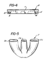
- Figure 5 is a perspective view of a trident for use with the method according to the invention;
- Figure 6 is a front elevational view of a handle for use with the razor made according to the invention; and
- Figure 7 is a side elevational view of the handle shown in Figure 6.
- Referring to Figure 4 a razor blade B having locating means in the form of
notches slots notches support surfaces 21a, 21b and 21c. - As can be seen by reference to Figure 4, the
support surfaces 21a, 21b and 21c engage the blade B generally in the areas shown by the phantom lines at the rear portion of the blade B opposite the cutting edge 11. Thus supported, the combination of the blade B and trident support member T form a male member around which a unitary blade support means and blade covering means is formed. The blade support means is in the form of aseat 15, whilst the blade covering means is in the form of acap 22. The seat has a support surface for supporting the blade B. - The actual plastic moulded shape can best be understood by reference to Figures 1, 2 and 3. As can be seen from Figures 3 and 5 the various
trident arm surfaces 21a, 21b and 21c correspond to the positioning of openings formed in the rearward portion of theblade seat 15. - The generally
rectangular seat 15 includes a back, longitudinally-extendingsupport bar 17, an essentially centrally positionedsupport bar 18 and a downwardly projectingsleeve 20, which forms the rearward portion of theblade seat 15; theblade seat 15 also includessides sides longitudinal support bar 17 andsupport bar 18 correspond generally to the trident top surfaces 21a and 21c while trident surface 21b corresponds to the opening in thesleeve 20 adjacent the blade B, in the preferred configuration. - When the trident support configuration is used,
sleeve 20 is open at the end, while if only a 2-pronged forked support is used to support the blade B, thesleeve 20 is closed with plastic at the support surface end abutting the blade b. - A
guard bar 16 is formed along the leading portion of theblade seat 15 and extends essentially parallel to therear support bar 17 andcentral support bar 18.Ribs support bar 18 to theguard bar 16. As can be seen more readily from Figure 2, the blade B only extends a short distance over thecentre support bar 18 with theguard bar ribs - The
cap 22 is moulded as a single unitary piece attached to theblade seat 15 by plastic which extends around the rear portion of the blade B and outward to form thecap 22 and also throughblade slots thermoplastics tabs cap 22 to theblade seat 15. Thetabs holes cap 22 to the blade B as well as to thecentre rib 18. Thesleeve 20 as can best be seen by reference to Figure 1, provides a site for a handle attachment designated 23. - In a preferred variation of this invention, the handle shown in Figures 6 and 7, and designated H, is preinserted into the mould prior to the formation of the blade and seat combination and, as part of the male portion of the mould, the
seat 15 andcap 22 are formed around it eliminating a subsequent moulding step. The preinserted handle H according to this invention can be made of plastic or other materials and if made of plastic can be inserted in the mould cavity used for the razor head or formed in the same mould used for the head. - The handle H includes gripping
area 25, having aflange 26 extending upwardly axially from ashoulder 29. Theflange 26, which is thinner than the grippingarea 25, includes aprojection 28 extending upward at an obtuse angle from its top portion. Atongue 27 extends axially outward from theprojection 28 depending from ashoulder 30; theshoulder 30 is provided on top of theprojection 28. Thetongue 27 contains anopening 31 which forms an anchor site for thesleeve 20 ofblade seat 15. Thus, when moulding is completed fluid thermoplastic forming theblade seat 15 has flowed through and around opening 31 andtongue 27 and set to provide a completed disposable razor. When this method is used, the trident centre of the support member T is modified to accept the handle. - While the fingered
cap 12 shown in Figure 1 is preferable, any particular configuration for a blade cover may be used. The present invention provides maximum support with minimum use of thermoplastics material and ease of mould removal from the male member form by the combination of the blade and mould blade support.
Claims (5)
Priority Applications (1)
| Application Number | Priority Date | Filing Date | Title |
|---|---|---|---|
| AT88303648T ATE68393T1 (en) | 1987-04-24 | 1988-04-22 | PROCESS FOR MAKING A RAZOR. |
Applications Claiming Priority (4)
| Application Number | Priority Date | Filing Date | Title |
|---|---|---|---|
| US42493 | 1987-04-24 | ||
| US07/042,493 US5053178A (en) | 1987-04-24 | 1987-04-24 | Process for insert molding disposable razor |
| US8836887A | 1987-08-21 | 1987-08-21 | |
| US88368 | 1987-08-21 |
Publications (2)
| Publication Number | Publication Date |
|---|---|
| EP0289228A1 EP0289228A1 (en) | 1988-11-02 |
| EP0289228B1 true EP0289228B1 (en) | 1991-10-16 |
Family
ID=26719305
Family Applications (1)
| Application Number | Title | Priority Date | Filing Date |
|---|---|---|---|
| EP88303648A Expired - Lifetime EP0289228B1 (en) | 1987-04-24 | 1988-04-22 | A method of making a razor |
Country Status (15)
| Country | Link |
|---|---|
| EP (1) | EP0289228B1 (en) |
| JP (1) | JP2817915B2 (en) |
| KR (1) | KR880012324A (en) |
| AR (1) | AR240148A1 (en) |
| AU (1) | AU604867B2 (en) |
| BR (1) | BR8801929A (en) |
| CA (1) | CA1298048C (en) |
| DE (1) | DE3865507D1 (en) |
| DK (1) | DK221088A (en) |
| ES (1) | ES2026651T3 (en) |
| GR (1) | GR3002921T3 (en) |
| HK (1) | HK112194A (en) |
| IL (1) | IL85420A (en) |
| MX (1) | MX167535B (en) |
| PT (1) | PT87289B (en) |
Cited By (4)
| Publication number | Priority date | Publication date | Assignee | Title |
|---|---|---|---|---|
| USD325653S (en) | 1990-02-05 | 1992-04-21 | American Safety Razor Company | Razor handle |
| USD415315S (en) | 1998-04-24 | 1999-10-12 | The Gillette Company | Razor cartridge |
| USD416108S (en) | 1998-04-24 | 1999-11-02 | The Gillette Company | Razor |
| USD524986S1 (en) | 2003-12-22 | 2006-07-11 | The Gillette Company | Razor cartridge |
Families Citing this family (3)
| Publication number | Priority date | Publication date | Assignee | Title |
|---|---|---|---|---|
| US5053178A (en) * | 1987-04-24 | 1991-10-01 | Warner-Lambert Company | Process for insert molding disposable razor |
| US5141694A (en) * | 1987-04-24 | 1992-08-25 | Warner-Lambert Company | Process for insert molding wet-shaving razor unit |
| US8611580B2 (en) | 2005-03-09 | 2013-12-17 | Plantronics, Inc. | Cheek stabilizer for audio headset |
Citations (3)
| Publication number | Priority date | Publication date | Assignee | Title |
|---|---|---|---|---|
| US2789346A (en) * | 1953-10-14 | 1957-04-23 | Algier Allen Phillip | Disposable safety razor |
| US3703765A (en) * | 1971-08-04 | 1972-11-28 | Gregorio A Perez | Disposable razor |
| GB1565296A (en) * | 1978-03-01 | 1980-04-16 | Gillette Co | Razor blades |
Family Cites Families (6)
| Publication number | Priority date | Publication date | Assignee | Title |
|---|---|---|---|---|
| US3070883A (en) * | 1959-06-09 | 1963-01-01 | Grathwohl Kenneth Tuthill | Disposable razor |
| GB1444545A (en) * | 1972-10-27 | 1976-08-04 | Wilkinson Sword Ltd | Shaving apparatus |
| CA1188086A (en) * | 1980-10-06 | 1985-06-04 | Robert A. Trotta | Shaving implement |
| KR830007239A (en) * | 1981-01-21 | 1983-10-19 | 윌킨슨 스워드 리밋티드 | How to make razor blades and razors |
| GB2155383A (en) * | 1984-02-18 | 1985-09-25 | Cyril Herbert Moss | Razors |
| GB2164597B (en) * | 1984-09-20 | 1988-02-10 | Wilkinson Sword Ltd | An improved razor blade assembly and its method of manufacture |
-
1988
- 1988-02-15 IL IL85420A patent/IL85420A/en unknown
- 1988-02-22 AR AR310128A patent/AR240148A1/en active
- 1988-03-01 CA CA000560217A patent/CA1298048C/en not_active Expired - Fee Related
- 1988-03-08 KR KR1019880002389A patent/KR880012324A/en not_active Abandoned
- 1988-03-24 JP JP63070819A patent/JP2817915B2/en not_active Expired - Fee Related
- 1988-03-31 AU AU14088/88A patent/AU604867B2/en not_active Ceased
- 1988-04-15 MX MX011140A patent/MX167535B/en unknown
- 1988-04-21 PT PT87289A patent/PT87289B/en not_active IP Right Cessation
- 1988-04-22 BR BR8801929A patent/BR8801929A/en unknown
- 1988-04-22 EP EP88303648A patent/EP0289228B1/en not_active Expired - Lifetime
- 1988-04-22 DK DK221088A patent/DK221088A/en not_active Application Discontinuation
- 1988-04-22 ES ES198888303648T patent/ES2026651T3/en not_active Expired - Lifetime
- 1988-04-22 DE DE8888303648T patent/DE3865507D1/en not_active Expired - Fee Related
-
1991
- 1991-10-17 GR GR91401478T patent/GR3002921T3/en unknown
-
1994
- 1994-10-12 HK HK112194A patent/HK112194A/en not_active IP Right Cessation
Patent Citations (3)
| Publication number | Priority date | Publication date | Assignee | Title |
|---|---|---|---|---|
| US2789346A (en) * | 1953-10-14 | 1957-04-23 | Algier Allen Phillip | Disposable safety razor |
| US3703765A (en) * | 1971-08-04 | 1972-11-28 | Gregorio A Perez | Disposable razor |
| GB1565296A (en) * | 1978-03-01 | 1980-04-16 | Gillette Co | Razor blades |
Cited By (4)
| Publication number | Priority date | Publication date | Assignee | Title |
|---|---|---|---|---|
| USD325653S (en) | 1990-02-05 | 1992-04-21 | American Safety Razor Company | Razor handle |
| USD415315S (en) | 1998-04-24 | 1999-10-12 | The Gillette Company | Razor cartridge |
| USD416108S (en) | 1998-04-24 | 1999-11-02 | The Gillette Company | Razor |
| USD524986S1 (en) | 2003-12-22 | 2006-07-11 | The Gillette Company | Razor cartridge |
Also Published As
| Publication number | Publication date |
|---|---|
| JPS6464682A (en) | 1989-03-10 |
| CA1298048C (en) | 1992-03-31 |
| DE3865507D1 (en) | 1991-11-21 |
| MX167535B (en) | 1993-03-29 |
| EP0289228A1 (en) | 1988-11-02 |
| KR880012324A (en) | 1988-11-26 |
| AU604867B2 (en) | 1991-01-03 |
| JP2817915B2 (en) | 1998-10-30 |
| AR240148A1 (en) | 1990-02-28 |
| ES2026651T3 (en) | 1992-05-01 |
| GR3002921T3 (en) | 1993-01-25 |
| HK112194A (en) | 1994-10-21 |
| DK221088D0 (en) | 1988-04-22 |
| PT87289B (en) | 1993-09-30 |
| AU1408888A (en) | 1988-10-27 |
| DK221088A (en) | 1988-10-25 |
| IL85420A0 (en) | 1988-07-31 |
| BR8801929A (en) | 1988-11-22 |
| IL85420A (en) | 1991-11-21 |
| PT87289A (en) | 1989-05-12 |
Similar Documents
| Publication | Publication Date | Title |
|---|---|---|
| EP0462807B1 (en) | Process for insert molding wet-shaving razor unit and unit made therefrom | |
| EP0288301B1 (en) | A method for making a razor | |
| EP0198854B1 (en) | A razor blade assembly | |
| US4901437A (en) | Razor head and method of manufacture | |
| EP1537964B1 (en) | Razor heads with intermediate guard elements | |
| EP1097788B1 (en) | Razor assembly | |
| EP0166617B1 (en) | One-piece disposable razor with blade protector | |
| US5318429A (en) | Process for insert molding wet-shaving razor unit and unit made therefrom | |
| EP0232135A2 (en) | Method of securing a shaving aid to a razor cartridge | |
| US4852254A (en) | Razor blade assembly and its method of manufacture | |
| HK112194A (en) | A method of making a razor | |
| US5104605A (en) | Process for insert molding disposable razor | |
| EP0470720B1 (en) | One-piece flexible razor head | |
| US4690018A (en) | Razor blade assembly and its method of manufacture | |
| CA2447154C (en) | Razor assembly | |
| JPH033514B2 (en) | ||
| HK1024884B (en) | Razor assembly |
Legal Events
| Date | Code | Title | Description |
|---|---|---|---|
| PUAI | Public reference made under article 153(3) epc to a published international application that has entered the european phase |
Free format text: ORIGINAL CODE: 0009012 |
|
| AK | Designated contracting states |
Kind code of ref document: A1 Designated state(s): AT BE CH DE ES FR GB GR IT LI LU NL SE |
|
| 17P | Request for examination filed |
Effective date: 19890428 |
|
| 17Q | First examination report despatched |
Effective date: 19891121 |
|
| ITF | It: translation for a ep patent filed | ||
| GRAA | (expected) grant |
Free format text: ORIGINAL CODE: 0009210 |
|
| AK | Designated contracting states |
Kind code of ref document: B1 Designated state(s): AT BE CH DE ES FR GB GR IT LI LU NL SE |
|
| REF | Corresponds to: |
Ref document number: 68393 Country of ref document: AT Date of ref document: 19911115 Kind code of ref document: T |
|
| ET | Fr: translation filed | ||
| REF | Corresponds to: |
Ref document number: 3865507 Country of ref document: DE Date of ref document: 19911121 |
|
| REG | Reference to a national code |
Ref country code: ES Ref legal event code: FG2A Ref document number: 2026651 Country of ref document: ES Kind code of ref document: T3 |
|
| PLBE | No opposition filed within time limit |
Free format text: ORIGINAL CODE: 0009261 |
|
| STAA | Information on the status of an ep patent application or granted ep patent |
Free format text: STATUS: NO OPPOSITION FILED WITHIN TIME LIMIT |
|
| REG | Reference to a national code |
Ref country code: GR Ref legal event code: FG4A Free format text: 3002921 |
|
| 26N | No opposition filed | ||
| PGFP | Annual fee paid to national office [announced via postgrant information from national office to epo] |
Ref country code: SE Payment date: 19940317 Year of fee payment: 7 |
|
| PGFP | Annual fee paid to national office [announced via postgrant information from national office to epo] |
Ref country code: AT Payment date: 19940318 Year of fee payment: 7 |
|
| PGFP | Annual fee paid to national office [announced via postgrant information from national office to epo] |
Ref country code: BE Payment date: 19940420 Year of fee payment: 7 |
|
| PGFP | Annual fee paid to national office [announced via postgrant information from national office to epo] |
Ref country code: NL Payment date: 19940430 Year of fee payment: 7 Ref country code: LU Payment date: 19940430 Year of fee payment: 7 |
|
| EPTA | Lu: last paid annual fee | ||
| PGFP | Annual fee paid to national office [announced via postgrant information from national office to epo] |
Ref country code: CH Payment date: 19940718 Year of fee payment: 7 |
|
| EAL | Se: european patent in force in sweden |
Ref document number: 88303648.5 |
|
| PG25 | Lapsed in a contracting state [announced via postgrant information from national office to epo] |
Ref country code: LU Free format text: LAPSE BECAUSE OF NON-PAYMENT OF DUE FEES Effective date: 19950422 Ref country code: AT Effective date: 19950422 |
|
| PG25 | Lapsed in a contracting state [announced via postgrant information from national office to epo] |
Ref country code: SE Effective date: 19950423 |
|
| PG25 | Lapsed in a contracting state [announced via postgrant information from national office to epo] |
Ref country code: LI Effective date: 19950430 Ref country code: CH Effective date: 19950430 Ref country code: BE Effective date: 19950430 |
|
| BERE | Be: lapsed |
Owner name: WARNER-LAMBERT CY Effective date: 19950430 |
|
| PG25 | Lapsed in a contracting state [announced via postgrant information from national office to epo] |
Ref country code: NL Effective date: 19951101 |
|
| REG | Reference to a national code |
Ref country code: CH Ref legal event code: PL |
|
| NLV4 | Nl: lapsed or anulled due to non-payment of the annual fee |
Effective date: 19951101 |
|
| EUG | Se: european patent has lapsed |
Ref document number: 88303648.5 |
|
| PGFP | Annual fee paid to national office [announced via postgrant information from national office to epo] |
Ref country code: ES Payment date: 19960412 Year of fee payment: 9 |
|
| PGFP | Annual fee paid to national office [announced via postgrant information from national office to epo] |
Ref country code: GR Payment date: 19960429 Year of fee payment: 9 |
|
| PG25 | Lapsed in a contracting state [announced via postgrant information from national office to epo] |
Ref country code: ES Free format text: LAPSE BECAUSE OF NON-PAYMENT OF DUE FEES Effective date: 19970423 |
|
| PG25 | Lapsed in a contracting state [announced via postgrant information from national office to epo] |
Ref country code: GR Free format text: THE PATENT HAS BEEN ANNULLED BY A DECISION OF A NATIONAL AUTHORITY Effective date: 19971031 |
|
| REG | Reference to a national code |
Ref country code: GR Ref legal event code: MM2A Free format text: 3002921 |
|
| REG | Reference to a national code |
Ref country code: ES Ref legal event code: FD2A Effective date: 19990405 |
|
| REG | Reference to a national code |
Ref country code: GB Ref legal event code: IF02 |
|
| PGFP | Annual fee paid to national office [announced via postgrant information from national office to epo] |
Ref country code: GB Payment date: 20030313 Year of fee payment: 16 |
|
| PGFP | Annual fee paid to national office [announced via postgrant information from national office to epo] |
Ref country code: FR Payment date: 20030403 Year of fee payment: 16 |
|
| PGFP | Annual fee paid to national office [announced via postgrant information from national office to epo] |
Ref country code: DE Payment date: 20030430 Year of fee payment: 16 |
|
| PG25 | Lapsed in a contracting state [announced via postgrant information from national office to epo] |
Ref country code: GB Free format text: LAPSE BECAUSE OF NON-PAYMENT OF DUE FEES Effective date: 20040422 |
|
| PG25 | Lapsed in a contracting state [announced via postgrant information from national office to epo] |
Ref country code: DE Free format text: LAPSE BECAUSE OF NON-PAYMENT OF DUE FEES Effective date: 20041103 |
|
| GBPC | Gb: european patent ceased through non-payment of renewal fee |
Effective date: 20040422 |
|
| PG25 | Lapsed in a contracting state [announced via postgrant information from national office to epo] |
Ref country code: FR Free format text: LAPSE BECAUSE OF NON-PAYMENT OF DUE FEES Effective date: 20041231 |
|
| REG | Reference to a national code |
Ref country code: FR Ref legal event code: ST |
|
| PG25 | Lapsed in a contracting state [announced via postgrant information from national office to epo] |
Ref country code: IT Free format text: LAPSE BECAUSE OF NON-PAYMENT OF DUE FEES;WARNING: LAPSES OF ITALIAN PATENTS WITH EFFECTIVE DATE BEFORE 2007 MAY HAVE OCCURRED AT ANY TIME BEFORE 2007. THE CORRECT EFFECTIVE DATE MAY BE DIFFERENT FROM THE ONE RECORDED. Effective date: 20050422 |