EP0289153B1 - System for posting articles into a containment - Google Patents
System for posting articles into a containment Download PDFInfo
- Publication number
- EP0289153B1 EP0289153B1 EP88303128A EP88303128A EP0289153B1 EP 0289153 B1 EP0289153 B1 EP 0289153B1 EP 88303128 A EP88303128 A EP 88303128A EP 88303128 A EP88303128 A EP 88303128A EP 0289153 B1 EP0289153 B1 EP 0289153B1
- Authority
- EP
- European Patent Office
- Prior art keywords
- containment
- drum
- port
- posting
- hoist
- Prior art date
- Legal status (The legal status is an assumption and is not a legal conclusion. Google has not performed a legal analysis and makes no representation as to the accuracy of the status listed.)
- Expired - Lifetime
Links
- 210000005070 sphincter Anatomy 0.000 claims description 17
- 239000012858 resilient material Substances 0.000 claims description 5
- 238000009792 diffusion process Methods 0.000 claims description 4
- 239000004677 Nylon Substances 0.000 description 2
- 238000010276 construction Methods 0.000 description 2
- 229920001778 nylon Polymers 0.000 description 2
- 239000002901 radioactive waste Substances 0.000 description 2
- 238000011109 contamination Methods 0.000 description 1
- 238000001514 detection method Methods 0.000 description 1
- 229920001971 elastomer Polymers 0.000 description 1
- 239000000463 material Substances 0.000 description 1
- 229920003052 natural elastomer Polymers 0.000 description 1
- 229920001194 natural rubber Polymers 0.000 description 1
- 239000005060 rubber Substances 0.000 description 1
- 229920003051 synthetic elastomer Polymers 0.000 description 1
- 239000005061 synthetic rubber Substances 0.000 description 1
- 238000009423 ventilation Methods 0.000 description 1
- 239000002699 waste material Substances 0.000 description 1
Images




Classifications
-
- G—PHYSICS
- G21—NUCLEAR PHYSICS; NUCLEAR ENGINEERING
- G21F—PROTECTION AGAINST X-RADIATION, GAMMA RADIATION, CORPUSCULAR RADIATION OR PARTICLE BOMBARDMENT; TREATING RADIOACTIVELY CONTAMINATED MATERIAL; DECONTAMINATION ARRANGEMENTS THEREFOR
- G21F7/00—Shielded cells or rooms
- G21F7/005—Shielded passages through walls; Locks; Transferring devices between rooms
Definitions
- the present invention concerns a port for posting articles into a containment which is maintained at sub-atmospheric pressure.
- the invention concerns a posting port having a sphincter seal for minimising back diffusion through the port during a posting operation.
- FR-A-2,049,259 discloses a means of providing a leaktight connection between the rear of a goods vehicle and an access opening in a building.
- the access opening is fitted with a removable door and had three flaps of an elastically resilient material which engage the top and sides of the goods vehicle as it passes through the opening, thereby forming a leaktight connection between the vehicle and the interior of the building.
- the prior art construction is not suitable for use with radioactive wastes. It is an object of the present invention to provide a construction that is so suitable.
- the present invention accordingly provides a system for posting articles into a containment maintained at sub-atmospheric pressure, comprising a posting port in a wall of the containment having a sphincter seal and a removable lid, the sphincter seal being such as to engage articles posted through the port and to permit an inward air flow into the containment to oppose back-diffusion from the containment, characterised in that the sphincter seal comprises an annular assembly of inner and outer brush seals between which are sandwiched rings of resilient material having a continuous elastic garter secured to the underside thereof.
- each ring of resilient material is divided into sectors which extend radially inwardly beyond the inner radius of the brush seals.
- the upper annular brushes of the assembly serve to protect the resilient member during the posting operation.
- the lower annular brushes serve to support the resilient member and help prevent permanent deformation. Both upper and lower brushes restrict the opening in the containment during posting operations.
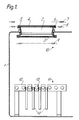
- a containment 1 is provided with a posting port 2 through which drums of radioactive waste materials can enter into the containment.
- the port 2 comprises an annular sphincter seal 3 and a removable lid or cover 4.
- the lid or cover 4 sealingly engages an inflatable seal 5 mounted in a lip 6 at the outer end of the port 2.
- Various detectors for controlling the sequence of operation are denoted by the reference numerals 7 to 11 respectively and the function of which will be described in the following description.
- a platform comprising a roller conveyor assembly 12 is located within the containment 1 below the port 2.
- a hoist 14 in the form of a fork cooperates with the conveyor assembly 12 such that the fork can pass between rollers 13 of the conveyor assembly. In Figure 1 the hoist is shown in a retracted position.
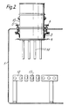
- the hoist 14 is raised to its highest position, which will be indicated by position switch 10, the lid or cover 4 is removed to expose the port 2, and a drum 15 supported by a crane or hoist (not shown) is lowered through the port on to the raised hoist 14.
- position switch 10 the lid or cover 4 is removed to expose the port 2
- a drum 15 supported by a crane or hoist (not shown) is lowered through the port on to the raised hoist 14.
- This position is depicted in Figure 2.
- the sphincter seal 3 engages the lower end of the drum 15.
- the detectors 7,8 and 9 can be infra-red switch devices and in Figure 2 the drum interrupts signals from transmitters to receivers at the detection positions.
- the hoist With the drum 15 on the hoist 14, the hoist is then lowered to lower the drum 15 into the containment until the drum lid 16 is level with or just below the lip 6 as shown in Figure 3. This is indicated by the detector 8 which initiates a signal to interrupt the hoist drive mechanism.
- the sphincter seal 3 remains at all times in engagement with the drum 15. During normal operation, a drum is always present in the port. This condition is only changed either at commencement of operation or if it becomes necessary to change and renew the sphincter seal.
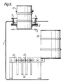
- a second drum 17, Figure 4 is then lowered by the external crane or hoist to above the drum 15.
- the drum 17 on breaking the signal at the detector 7 initiates a signal to recommence the hoist drive mechanism.
- the hoist 14 retracts to lower the drum 15 on to the roller conveyor assembly 12 and the fully withdrawn position of the hoist is indicated by a signal from detector 11 which stops the hoist drive mechanism.
- the drum 17, still supported by the external crane or hoist is at the same time lowered into the containment 1 and stops when the top of the drum 15 clears the detector 9. This position is shown in Figure 5.
- the sphincter seal 3 is now in engagement with the surface of the drum 17.
- the drum 17 is supported in the port by the external crane or hoist and the first drum 15 is moved off the roller conveyor assembly 12 and through an airlock door (not shown) into a work area within the containment. Thereafter, the airlock door is closed and the hoist 14 is raised again to its highest position as indicated by the detector 10. The drum 17 is lowered on to the hoist 14 and released from the external crane or hoist. This position is shown in Figure 7. The drum 17 is then lowered on the hoist until the detector 8 is again actuated. The lid 4 can then be closed to form a secondary seal arrangement (Figure 8). The drum 17 remains in this position, with the lid closed, until a further drum is ready for transfer through the port into the containment. The lid 4 is then reopened to allow the posting operation to take place.
- the sequence of operation is then repeated with the drums 17 and the further drum to be entered into the containment.
- the sphincter seal serves to reduce the opening between the interior of the containment and the atmosphere during posting operations such that the containment ventilation system can maintain an inward linear air flow, typically 1m/sec, thus preventing back diffusion of airborne contamination from the containment.
- the form of sphincter seal is shown in Figures 9 and 10.
- the seal 3 is an annular assembly comprising upper and lower brush seals 20 and 21, conveniently nylon brushes, between which are sandwiched rings of natural or synthetic rubber 22, each ring being divided into sectors.
- the rubber rings extend radially inwardly beyond the inner radius of the nylon brushes.
- a continuous elastic garter 23 is secured to the underside of the lowermost ring 22 projecting inwardly beyond the lower brush.
- the seal can accommodate changes in diameter of individual drums and also different sizes of drums.
- the garter 23 serves to resist deformation of the seal during use and ensures that the seal returns to its natural state after passage of a drum through the port.
Landscapes
- Physics & Mathematics (AREA)
- Engineering & Computer Science (AREA)
- General Engineering & Computer Science (AREA)
- High Energy & Nuclear Physics (AREA)
- Specific Sealing Or Ventilating Devices For Doors And Windows (AREA)
- Auxiliary Methods And Devices For Loading And Unloading (AREA)
- Sealing Devices (AREA)
- Filling Or Emptying Of Bunkers, Hoppers, And Tanks (AREA)
- Vacuum Packaging (AREA)
Description
- The present invention concerns a port for posting articles into a containment which is maintained at sub-atmospheric pressure. In particular the invention concerns a posting port having a sphincter seal for minimising back diffusion through the port during a posting operation.
- Systems for posting articles into a containment by means of a posting port having a sphincter seal are known. One such system is described in FR-A-2,049,259 which discloses a means of providing a leaktight connection between the rear of a goods vehicle and an access opening in a building. The access opening is fitted with a removable door and had three flaps of an elastically resilient material which engage the top and sides of the goods vehicle as it passes through the opening, thereby forming a leaktight connection between the vehicle and the interior of the building.
- The prior art construction is not suitable for use with radioactive wastes. It is an object of the present invention to provide a construction that is so suitable.
- The present invention accordingly provides a system for posting articles into a containment maintained at sub-atmospheric pressure, comprising a posting port in a wall of the containment having a sphincter seal and a removable lid, the sphincter seal being such as to engage articles posted through the port and to permit an inward air flow into the containment to oppose back-diffusion from the containment, characterised in that the sphincter seal comprises an annular assembly of inner and outer brush seals between which are sandwiched rings of resilient material having a continuous elastic garter secured to the underside thereof.
- Preferably, each ring of resilient material is divided into sectors which extend radially inwardly beyond the inner radius of the brush seals. The upper annular brushes of the assembly serve to protect the resilient member during the posting operation. The lower annular brushes serve to support the resilient member and help prevent permanent deformation. Both upper and lower brushes restrict the opening in the containment during posting operations.
- The invention will now be described further, by way of example, with reference to the accompanying drawings, in which:
- Figures 1 to 8 depict diagrammatically successive steps in the posting of waste drums into a containment; and
- Figs 9 and 10 are respectively a plan and section of a sphincter seal used at a posting port into the containment.
- In Figures 1 to 8, a
containment 1 is provided with aposting port 2 through which drums of radioactive waste materials can enter into the containment. Theport 2 comprises anannular sphincter seal 3 and a removable lid or cover 4. The lid or cover 4 sealingly engages aninflatable seal 5 mounted in alip 6 at the outer end of theport 2. Various detectors for controlling the sequence of operation are denoted by thereference numerals 7 to 11 respectively and the function of which will be described in the following description. A platform comprising aroller conveyor assembly 12 is located within thecontainment 1 below theport 2. Ahoist 14 in the form of a fork cooperates with theconveyor assembly 12 such that the fork can pass betweenrollers 13 of the conveyor assembly. In Figure 1 the hoist is shown in a retracted position. - To enter a first drum into the containment, the
hoist 14 is raised to its highest position, which will be indicated by position switch 10, the lid or cover 4 is removed to expose theport 2, and adrum 15 supported by a crane or hoist (not shown) is lowered through the port on to the raisedhoist 14. This position is depicted in Figure 2. Thesphincter seal 3 engages the lower end of thedrum 15. Thedetectors - With the
drum 15 on thehoist 14, the hoist is then lowered to lower thedrum 15 into the containment until the drum lid 16 is level with or just below thelip 6 as shown in Figure 3. This is indicated by thedetector 8 which initiates a signal to interrupt the hoist drive mechanism. Thesphincter seal 3 remains at all times in engagement with thedrum 15. During normal operation, a drum is always present in the port. This condition is only changed either at commencement of operation or if it becomes necessary to change and renew the sphincter seal. - During normal operation a
second drum 17, Figure 4, is then lowered by the external crane or hoist to above thedrum 15. Thedrum 17 on breaking the signal at thedetector 7 initiates a signal to recommence the hoist drive mechanism. Thehoist 14 retracts to lower thedrum 15 on to theroller conveyor assembly 12 and the fully withdrawn position of the hoist is indicated by a signal fromdetector 11 which stops the hoist drive mechanism. Thedrum 17, still supported by the external crane or hoist is at the same time lowered into thecontainment 1 and stops when the top of thedrum 15 clears thedetector 9. This position is shown in Figure 5. Thesphincter seal 3 is now in engagement with the surface of thedrum 17. - In Figure 6, the
drum 17 is supported in the port by the external crane or hoist and thefirst drum 15 is moved off theroller conveyor assembly 12 and through an airlock door (not shown) into a work area within the containment. Thereafter, the airlock door is closed and thehoist 14 is raised again to its highest position as indicated by the detector 10. Thedrum 17 is lowered on to thehoist 14 and released from the external crane or hoist. This position is shown in Figure 7. Thedrum 17 is then lowered on the hoist until thedetector 8 is again actuated. The lid 4 can then be closed to form a secondary seal arrangement (Figure 8). Thedrum 17 remains in this position, with the lid closed, until a further drum is ready for transfer through the port into the containment. The lid 4 is then reopened to allow the posting operation to take place. - The sequence of operation is then repeated with the
drums 17 and the further drum to be entered into the containment. - The sphincter seal serves to reduce the opening between the interior of the containment and the atmosphere during posting operations such that the containment ventilation system can maintain an inward linear air flow, typically 1m/sec, thus preventing back diffusion of airborne contamination from the containment.
- The form of sphincter seal is shown in Figures 9 and 10. The
seal 3 is an annular assembly comprising upper andlower brush seals synthetic rubber 22, each ring being divided into sectors. The rubber rings extend radially inwardly beyond the inner radius of the nylon brushes. A continuouselastic garter 23 is secured to the underside of thelowermost ring 22 projecting inwardly beyond the lower brush. As a drum is passed through the port the sphincter seal is deformed as indicated in Figures 1 to 8 but at all times maintains a positive contact with the drum over the periphery of the drum. The seal can accommodate changes in diameter of individual drums and also different sizes of drums. Thegarter 23 serves to resist deformation of the seal during use and ensures that the seal returns to its natural state after passage of a drum through the port.
Claims (2)
- A system for posting articles into a containment maintained at sub-atmospheric pressure, comprising a posting port (2) in a wall of the containment (1) having a sphincter seal (3) and a removable lid (4), the sphincter seal (3) being such as to engage articles posted through the port (2) and to permit an inward air flow into the containment (1) to oppose back-diffusion from the containment (1), characterised in that the sphincter seal (3) comprises an annular assembly of inner (21) and outer (20) brush seals between which are sandwiched rings of resilient material (22) having a continuous elastic garter (23) secured to the underside thereof.
- A system as claimed in Claim 1, wherein each ring of resilient material (22) is divided into sectors which extend radially inwardly beyond the inner radius of the brush seals (20,21).
Applications Claiming Priority (2)
| Application Number | Priority Date | Filing Date | Title |
|---|---|---|---|
| GB878710388A GB8710388D0 (en) | 1987-05-01 | 1987-05-01 | Posting ports |
| GB8710388 | 1987-05-01 |
Publications (3)
| Publication Number | Publication Date |
|---|---|
| EP0289153A2 EP0289153A2 (en) | 1988-11-02 |
| EP0289153A3 EP0289153A3 (en) | 1989-12-06 |
| EP0289153B1 true EP0289153B1 (en) | 1993-10-20 |
Family
ID=10616707
Family Applications (1)
| Application Number | Title | Priority Date | Filing Date |
|---|---|---|---|
| EP88303128A Expired - Lifetime EP0289153B1 (en) | 1987-05-01 | 1988-04-07 | System for posting articles into a containment |
Country Status (5)
| Country | Link |
|---|---|
| US (1) | US4984510A (en) |
| EP (1) | EP0289153B1 (en) |
| JP (1) | JP2656539B2 (en) |
| DE (1) | DE3884991T2 (en) |
| GB (1) | GB8710388D0 (en) |
Family Cites Families (5)
| Publication number | Priority date | Publication date | Assignee | Title |
|---|---|---|---|---|
| FR2049259A5 (en) * | 1969-06-05 | 1971-03-26 | Secmi | |
| FR2123059A1 (en) * | 1970-10-19 | 1972-09-08 | Commissariat Energie Atomique | Sample trolley - to transfer substances by remote control in a shielded chamber |
| GB1455876A (en) * | 1973-10-24 | 1976-11-17 | British Nuclear Fuels Ltd | Systems for transferring materials |
| US4582638A (en) * | 1981-03-27 | 1986-04-15 | General Signal Corporation | Method and means for disposal of radioactive waste |
| GB2116900B (en) * | 1982-02-18 | 1985-06-05 | Nat Nuclear Corp Ltd | Dry storage of irradiated nuclear fuel |
-
1987
- 1987-05-01 GB GB878710388A patent/GB8710388D0/en active Pending
-
1988
- 1988-04-07 EP EP88303128A patent/EP0289153B1/en not_active Expired - Lifetime
- 1988-04-07 DE DE88303128T patent/DE3884991T2/en not_active Expired - Fee Related
- 1988-04-11 US US07/180,081 patent/US4984510A/en not_active Expired - Lifetime
- 1988-04-28 JP JP63107481A patent/JP2656539B2/en not_active Expired - Lifetime
Also Published As
| Publication number | Publication date |
|---|---|
| US4984510A (en) | 1991-01-15 |
| EP0289153A2 (en) | 1988-11-02 |
| JP2656539B2 (en) | 1997-09-24 |
| DE3884991D1 (en) | 1993-11-25 |
| DE3884991T2 (en) | 1994-05-05 |
| GB8710388D0 (en) | 1987-06-03 |
| JPS63285498A (en) | 1988-11-22 |
| EP0289153A3 (en) | 1989-12-06 |
Similar Documents
| Publication | Publication Date | Title |
|---|---|---|
| ATE139505T1 (en) | CHILD-RESISTANT CLOSURE WITH INDICATOR | |
| AU691625B2 (en) | Container | |
| JP3732256B2 (en) | Sealing system and transfer system | |
| GB1594845A (en) | Vapour-sealing safety cap and container | |
| ATE139506T1 (en) | CHILD-RESISTANT CLOSURE WITH INDICATOR | |
| US5052451A (en) | Dust control apparatus | |
| US5036894A (en) | Material handling system | |
| US4016096A (en) | Method and device for closing a receptacle for radioactive wastes | |
| AU750037C (en) | Apparatus and system for handling material | |
| US4580694A (en) | Sealing mechanism for a double-lid seal structure | |
| ATE68431T1 (en) | CHILD RESISTANT DRIPPER/CAP SYSTEM. | |
| US5111854A (en) | Particle movement system with control of dust | |
| EP0293861A3 (en) | Electrode seal assembly | |
| ES2148203T3 (en) | PLASTIC CONTAINER CONTAINER PROVIDED WITH A WATERTIGHT CLOSING CLOSURE SYSTEM. | |
| US4984510A (en) | System for posting articles into a containment | |
| US7690406B2 (en) | Hazardous waste transfer port system and storage container | |
| US6199606B1 (en) | Material handling apparatus | |
| US4972652A (en) | Closures for containers | |
| DE59305527D1 (en) | Tamper-evident closure | |
| US4760268A (en) | Container for low or medium activity radioactive waste | |
| ATE103653T1 (en) | SHAFT CONSTRUCTION FOR CONTROL OR DRAINAGE SHAFT. | |
| GB2216049A (en) | Charging material into a container and closing the container | |
| EP0303864A3 (en) | Silo for powdery and fine grained bulk goods | |
| JP2001088897A (en) | Granular material transport container, granular material supply device, and granular material discharging method | |
| GB1502978A (en) | Closure of vessels having circular openings |
Legal Events
| Date | Code | Title | Description |
|---|---|---|---|
| PUAI | Public reference made under article 153(3) epc to a published international application that has entered the european phase |
Free format text: ORIGINAL CODE: 0009012 |
|
| AK | Designated contracting states |
Kind code of ref document: A2 Designated state(s): DE FR GB IT |
|
| PUAL | Search report despatched |
Free format text: ORIGINAL CODE: 0009013 |
|
| AK | Designated contracting states |
Kind code of ref document: A3 Designated state(s): DE FR GB IT |
|
| 17P | Request for examination filed |
Effective date: 19900525 |
|
| 17Q | First examination report despatched |
Effective date: 19920814 |
|
| GRAA | (expected) grant |
Free format text: ORIGINAL CODE: 0009210 |
|
| AK | Designated contracting states |
Kind code of ref document: B1 Designated state(s): DE FR GB IT |
|
| ET | Fr: translation filed | ||
| ITF | It: translation for a ep patent filed | ||
| REF | Corresponds to: |
Ref document number: 3884991 Country of ref document: DE Date of ref document: 19931125 |
|
| PLBE | No opposition filed within time limit |
Free format text: ORIGINAL CODE: 0009261 |
|
| STAA | Information on the status of an ep patent application or granted ep patent |
Free format text: STATUS: NO OPPOSITION FILED WITHIN TIME LIMIT |
|
| 26N | No opposition filed | ||
| PGFP | Annual fee paid to national office [announced via postgrant information from national office to epo] |
Ref country code: FR Payment date: 19980312 Year of fee payment: 11 |
|
| PGFP | Annual fee paid to national office [announced via postgrant information from national office to epo] |
Ref country code: GB Payment date: 19980320 Year of fee payment: 11 |
|
| PGFP | Annual fee paid to national office [announced via postgrant information from national office to epo] |
Ref country code: DE Payment date: 19980325 Year of fee payment: 11 |
|
| PG25 | Lapsed in a contracting state [announced via postgrant information from national office to epo] |
Ref country code: GB Free format text: LAPSE BECAUSE OF NON-PAYMENT OF DUE FEES Effective date: 19990407 |
|
| GBPC | Gb: european patent ceased through non-payment of renewal fee |
Effective date: 19990407 |
|
| PG25 | Lapsed in a contracting state [announced via postgrant information from national office to epo] |
Ref country code: FR Free format text: LAPSE BECAUSE OF NON-PAYMENT OF DUE FEES Effective date: 19991231 |
|
| REG | Reference to a national code |
Ref country code: FR Ref legal event code: ST |
|
| PG25 | Lapsed in a contracting state [announced via postgrant information from national office to epo] |
Ref country code: DE Free format text: LAPSE BECAUSE OF NON-PAYMENT OF DUE FEES Effective date: 20000201 |
|
| PG25 | Lapsed in a contracting state [announced via postgrant information from national office to epo] |
Ref country code: IT Free format text: LAPSE BECAUSE OF NON-PAYMENT OF DUE FEES;WARNING: LAPSES OF ITALIAN PATENTS WITH EFFECTIVE DATE BEFORE 2007 MAY HAVE OCCURRED AT ANY TIME BEFORE 2007. THE CORRECT EFFECTIVE DATE MAY BE DIFFERENT FROM THE ONE RECORDED. Effective date: 20050407 |