EP0289147A2 - Piling - Google Patents
Piling Download PDFInfo
- Publication number
- EP0289147A2 EP0289147A2 EP88302971A EP88302971A EP0289147A2 EP 0289147 A2 EP0289147 A2 EP 0289147A2 EP 88302971 A EP88302971 A EP 88302971A EP 88302971 A EP88302971 A EP 88302971A EP 0289147 A2 EP0289147 A2 EP 0289147A2
- Authority
- EP
- European Patent Office
- Prior art keywords
- auger
- stem
- extraction
- duct
- pile
- Prior art date
- Legal status (The legal status is an assumption and is not a legal conclusion. Google has not performed a legal analysis and makes no representation as to the accuracy of the status listed.)
- Withdrawn
Links
Images
Classifications
-
- E—FIXED CONSTRUCTIONS
- E02—HYDRAULIC ENGINEERING; FOUNDATIONS; SOIL SHIFTING
- E02D—FOUNDATIONS; EXCAVATIONS; EMBANKMENTS; UNDERGROUND OR UNDERWATER STRUCTURES
- E02D15/00—Handling building or like materials for hydraulic engineering or foundations
- E02D15/02—Handling of bulk concrete specially for foundation or hydraulic engineering purposes
- E02D15/04—Placing concrete in mould-pipes, pile tubes, bore-holes or narrow shafts
Definitions
- the present invention relates generally to a method of piling comprising inserting or screwing an auger into the ground until the required depth is reached, to form a bore and extracting the auger and passing a settable pile-forming material into the ground as the auger is extracted using a duct associated with the auger and which is extracted as the auger is extracted, in order to form a pile.
- the auger As the auger is extracted, it lifts spoil out of the bore.
- the settable material will be concrete or grout and normally the duct will be a hollow stem of the auger itself. Normally the auger will have a substantially continuous flight.
- the present invention provides methods as set forth in Claims 1, 2 or 3 and an auger as set forth in Claim 8.
- the remaining Claims set forth preferred features of the invention.
- simple conductivity sensing provides an arrangement which can resist the very aggressive environment in which the auger will be working - the ground can contain bricks or gravel or pieces of rock, etc., and the inside of the stem is subject to abrasion from the pumped settable material.
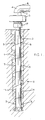
- the auger has a hollow stem 1, a continous flight 2, a rotary drive head 3, and a steel swivel assembly 4 for connection to a concrete pump (not shown).
- the auger has a number of conductivity monitors or sensors 5. There are typically two diametrically-opposed monitors 5 adjacent the bottom of the auger, i.e. adjacent to the point of injection, and there are other monitors higher up. The positioning of the monitors 5 depends upon the length of the auger and ground conditions (for instance wet sand and gravel well below the water table may require a much higher head of concrete than stiff clay); in general, it is desireable to have concrete about half way up the auger. There should be monitors 5 located at this level; additional monitors 5 near the top and bottom of the auger have been found useful.
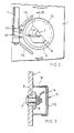
- FIGS 2 and 3 show one monitor 5.
- the monitor 5 is operative on the inside of the stem 1 and is in the form of a screwed insert 6 carrying a steel probe 7 with a suitable insulating sleeve 8.
- a pipe 11 (such as a gas barrel) is strongly welded to the auger stem 1 and has suitable Tee-pieces 12 having short branch pipes 13 which penetrate the respective housings 9, enabling leads 14 to be taken to the probes 7.
- the housings 9 can be protected by welded-on strapping 15.
- slip rings 16 can be used with sliding contacts carried on a stationary annular housing 17 suspended below the drive head 3 with a suitable gland packing or water-proofing 18. Further pairs of slip rings can be added for each pair of monitors 5.
- Figure 1 shows a single auger of for instance 6 m or 8 m length, but a string of augers can be made up for piling to greater depths. Joints can be formed between lengths of auger by providing suitable joints for the pipes 11 and connectors for the leads 14.
- an electric current is passed between the head of one probe 7 and the diametrically-opposed probe 7 and the electrical conductivity is monitored between the probes 7. If the concrete becomes depleted, air (normally under reduced pressure) will be present and the conductivity will fall sharply. The current flowing can be indicated on ammeters 19 for the various pairs of probes 7.
- monitors 5 can be provided on the swivel assembly 4, or they can even be provided closer to the concrete pump.
- the concrete pump is the conventional piston pump
- the monitors 5 above the drive head 3 can detect surges or pulses in the concrete; as it is known what volume of concrete is pumped by each stroke or cycle of the pump, this detection can give a good indication of the rate of flow.
- This mechanism appears to be a change in conductivity when there is a pressure stroke from the pump which is clearly distinguishable from both the 'pause' stroke of the pump and the case when there is air only between the monitors 5.
- one probe 7 could be used with the auger stem 1 itself acting as the other pole (at earth potential).
Landscapes
- Engineering & Computer Science (AREA)
- General Engineering & Computer Science (AREA)
- Structural Engineering (AREA)
- Life Sciences & Earth Sciences (AREA)
- General Life Sciences & Earth Sciences (AREA)
- Mining & Mineral Resources (AREA)
- Paleontology (AREA)
- Civil Engineering (AREA)
- Investigating Or Analyzing Materials By The Use Of Electric Means (AREA)
- Investigation Of Foundation Soil And Reinforcement Of Foundation Soil By Compacting Or Drainage (AREA)
- Piles And Underground Anchors (AREA)
- Earth Drilling (AREA)
Abstract
Description
- The present invention relates generally to a method of piling comprising inserting or screwing an auger into the ground until the required depth is reached, to form a bore and extracting the auger and passing a settable pile-forming material into the ground as the auger is extracted using a duct associated with the auger and which is extracted as the auger is extracted, in order to form a pile. As the auger is extracted, it lifts spoil out of the bore. Normally, the settable material will be concrete or grout and normally the duct will be a hollow stem of the auger itself. Normally the auger will have a substantially continuous flight.
- One cannot rely upon the volume of concrete required corresponding to the volume of the flow. If the soil is poor, concrete flows out laterally into the soil and considerably more concrete is required. The amount of concrete required per unit time depends primarily upon the rate of extraction of the auger which determins the rate of formation of the void to be occupied by the concrete. The rate of extraction must not be so fast that a larger void is being formed than can be filled by the inflowing concrete. However too slow a rate is uneconomic, wastes concrete and can cause practical difficulties in extracting the auger. The correct extraction rate is therefore important for the satisfactory formation of the pile, and it is desirable to find a method in which there is reasonable certainty of the correct withdrawal rate being used.
- The present invention provides methods as set forth in
Claims Claim 8. The remaining Claims set forth preferred features of the invention. - By sensing the conductivity (or other property) of the contents of the duct or stem, one can determine the level of the concrete (or other settable material) during extraction. If the level is above the conductivity sensor or probe, a higher conductivity will be sensed. Provided the level is kept above a certain critical level at all times, the pile will be satisfactorily formed. Although essentially very simple, this invention can lead to improved formation of piles and reduced wastage of concrete.
- Although more sophisticated methods of sensing may in theory be possible, it is found that simple conductivity sensing provides an arrangement which can resist the very aggressive environment in which the auger will be working - the ground can contain bricks or gravel or pieces of rock, etc., and the inside of the stem is subject to abrasion from the pumped settable material.
- The invention will be further described, by way of example, in which:
- Figure 1 is a schematic view, showing a continous flight auger of the invention, being screwed into the ground;
- Figure 2 is a detail looking in the direction of the arrow II in Figure 1;
- Figure 3 is a section along the line III-III in Figure 2;
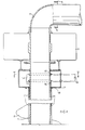
- Figure 4 is an axial section. on an enlarged scale compared to Figure 1, of the head of the auger; and
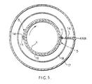
- Figure 5 is a section along the line IV-IV in Figure 4.
- The auger has a
hollow stem 1, acontinous flight 2, arotary drive head 3, and asteel swivel assembly 4 for connection to a concrete pump (not shown). - The auger has a number of conductivity monitors or
sensors 5. There are typically two diametrically-opposedmonitors 5 adjacent the bottom of the auger, i.e. adjacent to the point of injection, and there are other monitors higher up. The positioning of themonitors 5 depends upon the length of the auger and ground conditions (for instance wet sand and gravel well below the water table may require a much higher head of concrete than stiff clay); in general, it is desireable to have concrete about half way up the auger. There should bemonitors 5 located at this level;additional monitors 5 near the top and bottom of the auger have been found useful. - Figures 2 and 3 show one
monitor 5. Themonitor 5 is operative on the inside of thestem 1 and is in the form of ascrewed insert 6 carrying asteel probe 7 with a suitableinsulating sleeve 8. There is aprotective housing 9 with ascrew cap 10. - A pipe 11 (such as a gas barrel) is strongly welded to the
auger stem 1 and has suitable Tee-pieces 12 havingshort branch pipes 13 which penetrate therespective housings 9, enablingleads 14 to be taken to theprobes 7. Thehousings 9 can be protected by welded-on strapping 15. - The
leads 14 have to be taken out in a suitable manner since the auger stem is continuously rotating during drilling and construction of the pile. Figure 4 shows thatslip rings 16 can be used with sliding contacts carried on a stationaryannular housing 17 suspended below thedrive head 3 with a suitable gland packing or water-proofing 18. Further pairs of slip rings can be added for each pair ofmonitors 5. - Figure 1 shows a single auger of for instance 6 m or 8 m length, but a string of augers can be made up for piling to greater depths. Joints can be formed between lengths of auger by providing suitable joints for the
pipes 11 and connectors for theleads 14. - In the present assembly, an electric current is passed between the head of one
probe 7 and the diametrically-opposed probe 7 and the electrical conductivity is monitored between theprobes 7. If the concrete becomes depleted, air (normally under reduced pressure) will be present and the conductivity will fall sharply. The current flowing can be indicated onammeters 19 for the various pairs ofprobes 7. - Monitoring the conductivity at different levels enables information to be provided to the operator, so that he can control the extraction more precisely. As shown in Figures 1 and 4,
monitors 5 can be provided on theswivel assembly 4, or they can even be provided closer to the concrete pump. Particularly if the concrete pump is the conventional piston pump themonitors 5 above thedrive head 3 can detect surges or pulses in the concrete; as it is known what volume of concrete is pumped by each stroke or cycle of the pump, this detection can give a good indication of the rate of flow. This mechanism appears to be a change in conductivity when there is a pressure stroke from the pump which is clearly distinguishable from both the 'pause' stroke of the pump and the case when there is air only between themonitors 5. - It is not essential that the conductivity should be measured between opposed, localised monitors. For instance, one
probe 7 could be used with theauger stem 1 itself acting as the other pole (at earth potential). - The present invention has been described above purely by way of example, and modifications can be made within the spirit of the invention. Pressure sensors, or other means of measuring physical properties that indicates the presence or absence of concrete or grout, could be used in place of the electrical conductivity sensors.
Claims (9)
Applications Claiming Priority (2)
| Application Number | Priority Date | Filing Date | Title |
|---|---|---|---|
| GB8707907A GB2202885B (en) | 1987-04-02 | 1987-04-02 | Piling and auger therefor |
| GB8707907 | 1987-04-02 |
Publications (2)
| Publication Number | Publication Date |
|---|---|
| EP0289147A2 true EP0289147A2 (en) | 1988-11-02 |
| EP0289147A3 EP0289147A3 (en) | 1990-02-07 |
Family
ID=10615130
Family Applications (1)
| Application Number | Title | Priority Date | Filing Date |
|---|---|---|---|
| EP88302971A Withdrawn EP0289147A3 (en) | 1987-04-02 | 1988-03-31 | Piling |
Country Status (2)
| Country | Link |
|---|---|
| EP (1) | EP0289147A3 (en) |
| GB (1) | GB2202885B (en) |
Cited By (2)
| Publication number | Priority date | Publication date | Assignee | Title |
|---|---|---|---|---|
| US5437445A (en) * | 1992-10-08 | 1995-08-01 | Pitney Bowes Inc. | Method and apparatus for detecting double fed sheets |
| EP0940505A3 (en) * | 1998-03-06 | 2000-01-26 | Bauer Spezialtiefbau GmbH | Device for making a foundation pile in the ground |
Families Citing this family (3)
| Publication number | Priority date | Publication date | Assignee | Title |
|---|---|---|---|---|
| GB2328700B (en) * | 1995-07-31 | 1999-04-14 | Kvaerner Cementation Found Ltd | Improved auger piling |
| GB2362674A (en) * | 2000-05-26 | 2001-11-28 | Pennine Holdings Ltd | Auger with helical flight and fluid channel |
| CN110485383B (en) * | 2019-07-31 | 2021-05-18 | 中国一冶集团有限公司 | Monitoring device and monitoring method for water gate bottom plate void in weak area |
Family Cites Families (5)
| Publication number | Priority date | Publication date | Assignee | Title |
|---|---|---|---|---|
| US2213486A (en) * | 1938-06-06 | 1940-09-03 | Dale Service Corp | Level indicator for use in cementing wells |
| US2261495A (en) * | 1939-04-14 | 1941-11-04 | Gordon E Ewertz | Liquid level responsive device |
| US3200599A (en) * | 1960-12-23 | 1965-08-17 | Raymond Int Inc | Method for forming piles in situ |
| US3255592A (en) * | 1961-05-01 | 1966-06-14 | Herman L Moor | Control system for discharging concrete grout to form piles |
| US3335334A (en) * | 1963-07-08 | 1967-08-08 | Molson Breweries Ltd | Liquid level sensing device |
-
1987
- 1987-04-02 GB GB8707907A patent/GB2202885B/en not_active Expired - Fee Related
-
1988
- 1988-03-31 EP EP88302971A patent/EP0289147A3/en not_active Withdrawn
Cited By (2)
| Publication number | Priority date | Publication date | Assignee | Title |
|---|---|---|---|---|
| US5437445A (en) * | 1992-10-08 | 1995-08-01 | Pitney Bowes Inc. | Method and apparatus for detecting double fed sheets |
| EP0940505A3 (en) * | 1998-03-06 | 2000-01-26 | Bauer Spezialtiefbau GmbH | Device for making a foundation pile in the ground |
Also Published As
| Publication number | Publication date |
|---|---|
| GB8707907D0 (en) | 1987-05-07 |
| EP0289147A3 (en) | 1990-02-07 |
| GB2202885A (en) | 1988-10-05 |
| GB2202885B (en) | 1990-11-07 |
Similar Documents
| Publication | Publication Date | Title |
|---|---|---|
| CA2228518C (en) | Improved auger piling | |
| CA2147610C (en) | System for measuring the distance between two parallel boreholes or wells | |
| EP0656547B1 (en) | Method and appparatus for surveying and monitoring a hydrocarbon reservoir | |
| AU784759B2 (en) | Method and apparatus for monitoring the advance of seawater into fresh water aquifers near coastal cities | |
| JP6211049B2 (en) | Grout material detection method | |
| KR101043746B1 (en) | Ground monitoring unit and ground reinforcement device including the same | |
| KR102112545B1 (en) | Moisture content measuring device which can prevent disturbance of soil ground | |
| EP0289147A2 (en) | Piling | |
| JP4006884B2 (en) | Groundwater status logging method and device | |
| JP2001200529A (en) | Method for monitoring diameter of column formed by injection | |
| JP5268070B2 (en) | Slime property management method and automatic slime processing equipment | |
| Wadood et al. | Field monitoring and instrumentation in microtunnelling/pipe jacking: A review and future directions | |
| JPH0841860A (en) | Improvement examining method of soil improvement work and device used therefor | |
| GB2119100A (en) | A method of, and an apparatus for surveying a region of soil to which a stabilising chemical has been added | |
| JP2700184B2 (en) | Ground permeability test equipment | |
| JPH0533344A (en) | Mortar liquid surface detecting method and liquid level gage therefor | |
| CN112411557A (en) | Underground continuous wall and micro-disturbance omnibearing jet grouting pile combined water stopping method | |
| CN116255191B (en) | Separation layer grouting sleeve device and grouting process real-time detection and early warning method thereof | |
| JPH0961540A (en) | Electrical logging method and method for installing conductor pipe for electric logging | |
| CN103161454A (en) | Method for horizontal geological exploration by means of directional drilling machine | |
| Daw | Application of aquifer testing to deep shaft investigations | |
| JPS6239946B2 (en) | ||
| CA1246710A (en) | Method and apparatus for optimizing determination of the originating depth of borehole cuttings | |
| Amoozegar | 3.4. 3.5 Piezometer Method (Saturated Zone) | |
| Claesson et al. | Forsmark Site Investigation: Drilling of the Telescopic Borehole KFM11A at Drill Site DS 11 |
Legal Events
| Date | Code | Title | Description |
|---|---|---|---|
| PUAI | Public reference made under article 153(3) epc to a published international application that has entered the european phase |
Free format text: ORIGINAL CODE: 0009012 |
|
| AK | Designated contracting states |
Kind code of ref document: A2 Designated state(s): AT BE CH DE ES FR GR IT LI LU NL SE |
|
| PUAL | Search report despatched |
Free format text: ORIGINAL CODE: 0009013 |
|
| AK | Designated contracting states |
Kind code of ref document: A3 Designated state(s): AT BE CH DE ES FR GR IT LI LU NL SE |
|
| 17P | Request for examination filed |
Effective date: 19900807 |
|
| 17Q | First examination report despatched |
Effective date: 19920109 |
|
| STAA | Information on the status of an ep patent application or granted ep patent |
Free format text: STATUS: THE APPLICATION HAS BEEN WITHDRAWN |
|
| 18W | Application withdrawn |
Withdrawal date: 19920518 |