EP0289062A2 - Verfahren und Anordnung für das Messen des Leitvermögens einer Flüssigkeit mit Kontrolle des Übergangswiederstands zwischen Elektode und Flüssigkeit - Google Patents
Verfahren und Anordnung für das Messen des Leitvermögens einer Flüssigkeit mit Kontrolle des Übergangswiederstands zwischen Elektode und Flüssigkeit Download PDFInfo
- Publication number
- EP0289062A2 EP0289062A2 EP88200532A EP88200532A EP0289062A2 EP 0289062 A2 EP0289062 A2 EP 0289062A2 EP 88200532 A EP88200532 A EP 88200532A EP 88200532 A EP88200532 A EP 88200532A EP 0289062 A2 EP0289062 A2 EP 0289062A2
- Authority
- EP
- European Patent Office
- Prior art keywords
- current
- voltage
- electrodes
- electrode
- liquid
- Prior art date
- Legal status (The legal status is an assumption and is not a legal conclusion. Google has not performed a legal analysis and makes no representation as to the accuracy of the status listed.)
- Granted
Links
Images

Classifications
-
- G—PHYSICS
- G01—MEASURING; TESTING
- G01R—MEASURING ELECTRIC VARIABLES; MEASURING MAGNETIC VARIABLES
- G01R27/00—Arrangements for measuring resistance, reactance, impedance, or electric characteristics derived therefrom
- G01R27/02—Measuring real or complex resistance, reactance, impedance, or other two-pole characteristics derived therefrom, e.g. time constant
- G01R27/22—Measuring resistance of fluids
Definitions
- the invention relates to a method for measuring the conductivity of a liquid in which a current is fed through a liquid via first or current electrodes, which current is measured and the voltage of voltage electrodes is measured current-free, the voltage electrodes being positioned in the current field of the current electrodes and to a device for applying the method.
- This method for measuring the conductivity of a liquid has the advantage that the measured value of this conductivity in a relatively high degree is independent on the transfer resistance between the electrode and the liquid. Further any influence of polarisation on the current electrodes is compensated in a high degree, also because no polarisation will occur at the voltage electrodes.
- a serious drawback of such a device is, that with soiling of the electrode a considerable time no disturbances are established until the electrode is soiled in a degree that it can become insulated, which would put the measurement out of action, which fact can inflict great damages, for instance with continuous control of a process.
- the invention aims to provide, with simple means, the possibility to establish the increase of the transfer resistance between an electrode and the liquid.
- the invention provides a method as defined in claim 1 and a device as defined in claim 3.
- a simple embodiment of the invention provides that the further voltage is that between two current electrodes.
- Such a course of matters generally is satisfactory, but in case one wants to know, which of the current electrodes is soiled to which extend, it is also possible to measure the voltage between a current electrode and one of the voltage electrodes.
- the voltage measurement between a voltage electrode and a current electrode has also to be a current-free measurement.
- the invention further encompasses a device for applying the method, which device is provided with a current source connected to current electrode terminals, a current meter being present for measuring the current flowing between the current electrodes and a voltage measuring circuit, which is connectable with voltage electrodes and is adapted for current-free measuring of the voltage between voltage electrodes and is characterized in that at least one further voltage measuring circuit is present connected between a current electrode terminal and a terminal of another current electrode or a terminal of a voltage electrode and that a comparator device is connected to both voltage measuring circuits and is adapted to determine the proportion of the measured voltages.
- measuring circuits may be provided for current-free measuring of voltages between the terminal of
- An extremely simple embodiment of the inventive device is obtained with a voltage measuring circuit between the current electrodes, a voltage measuring circuit for current-free voltage measurement between the voltage electrodes and a device for ascertaining the proportion of these voltages, as well as a device for comparing this proportion with a predetermined value.
- the invention can be applied for direct current and/or one phase alternating current. If one wants to measure for any reason with for instance three phase alternating voltage, then three current electrodes may be used.
- the liquid is not homogeneous and that in the current field of two or more current electrodes has to be measured at more than one location with different voltage electrodes, for instance by splitting up a voltage electrode or by application of more than one set.
- the invention is directed to measure the conductivity, it is not necessary that the current flow through the liquid is only realized in view of said measurement. So the invention is also applicable in cases in which the current flow serves another purpose, such as electrolysis or suchlike, wherewith apart from the conductivity of the liquid also the transfer resistance between the liquid and a current carrying electrode is important.
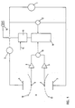
- the voltage measured by means of voltage meter 10 is fed to a computing device, which also receives from voltage meter 12 the voltage existing between electrodes 3 and 5.
- the device 11 determines the quotient of these voltages and feeds it to a comparator device 13, which has a schematical input 14 to adjust a comparation value.
- the output of the comparator device 13 is connected to an alarm device 15.
- the shape of the current field in the liquid 4 changes and consequently the location of the electrodes 6 and 7 with respect to this current field.
- the voltage indicated by voltage meter 12 will increase without increase of the voltage indicated by voltage meter 10. This forms an indication, that on one or both of the electrodes a resistance has been formed.
- the comparator device 13 the measured quotient of the voltages between the electrodes 6 and 7 and the electrodes 3 and 5 is compared with a fixed value, which either can be determined experimentally with clean electrodes or is a characterizing quantity for the used installation. Signalling a too big deviation can form an indication to clean or replace the electrodes 3 and 5.
- the processor 22 receives also the voltage 12 to check in that way whether the sum of the voltages of the voltage meters 20, 10 and 21 equals that of the voltage meter 12 or not. If this is not the case this fact has to signalled too.
- fig. 2 is only a scheme and it is for instance possible to let the voltage meters 20,10 and 21 exist in a single one, which alternately is switched on the outputs of the differential amplifiers 18,8; 8,9 and 9,19.
- the processor 22 can again receive adjustment quantities 14 ⁇ and 14 ⁇ , which indicate the proportions of the voltages indicated by the voltage meters 20,21 and 10 with unsoiled electrodes.
- the processor 22 can cooperate with display means to determine and indicate the specific conductivity or the specific resistance of the liquid 4 from the current measured by meter 2 and the voltage occurring between the voltage electrodes 6 and 7. Also the resistances, due to soiling of each of the electrodes 3 and 5 can be indicated.
- the voltage between electrodes 3 and 6 is proportional to the resistance of the liquid body between electrodes 3 and equipotential surface 16, that between electrodes 6 and 7 to the resistance of the liquid body between the equipotential surfaces 16 and 17 and that between 7 and 5 to the resistance of the liquid body between the equipotential surface 17 and the electrode 5.
- source 1 is a voltage source, so that meter 2 serves the purpose of current measurement.
- this predetermined current is the "measured" current value and current meter 2 is superfluous.
Landscapes
- Physics & Mathematics (AREA)
- General Physics & Mathematics (AREA)
- Investigating Or Analyzing Materials By The Use Of Electric Means (AREA)
- Measurement Of Resistance Or Impedance (AREA)
Priority Applications (1)
| Application Number | Priority Date | Filing Date | Title |
|---|---|---|---|
| AT88200532T ATE79958T1 (de) | 1987-03-24 | 1988-03-23 | Verfahren und anordnung fuer das messen des leitvermoegens einer fluessigkeit mit kontrolle des uebergangswiederstands zwischen elektode und fluessigkeit. |
Applications Claiming Priority (2)
| Application Number | Priority Date | Filing Date | Title |
|---|---|---|---|
| NL8700688 | 1987-03-24 | ||
| NL8700688A NL8700688A (nl) | 1987-03-24 | 1987-03-24 | Werkwijze en inrichting voor het meten van het geleidingsvermogen van een vloeistof met controle van de overgangsweerstand tussen een elektrode en de vloeistof. |
Publications (3)
| Publication Number | Publication Date |
|---|---|
| EP0289062A2 true EP0289062A2 (de) | 1988-11-02 |
| EP0289062A3 EP0289062A3 (en) | 1988-11-09 |
| EP0289062B1 EP0289062B1 (de) | 1992-08-26 |
Family
ID=19849752
Family Applications (1)
| Application Number | Title | Priority Date | Filing Date |
|---|---|---|---|
| EP88200532A Expired - Lifetime EP0289062B1 (de) | 1987-03-24 | 1988-03-23 | Verfahren und Anordnung für das Messen des Leitvermögens einer Flüssigkeit mit Kontrolle des Übergangswiederstands zwischen Elektode und Flüssigkeit |
Country Status (5)
| Country | Link |
|---|---|
| EP (1) | EP0289062B1 (de) |
| JP (1) | JPH0640080B2 (de) |
| AT (1) | ATE79958T1 (de) |
| DE (1) | DE3873967D1 (de) |
| NL (1) | NL8700688A (de) |
Cited By (1)
| Publication number | Priority date | Publication date | Assignee | Title |
|---|---|---|---|---|
| DE19704494A1 (de) * | 1997-02-07 | 1998-08-13 | Rossendorf Forschzent | Anordnung zur Messung der elektrischen Leitfähigkeit mittels Sonden sowie zur Sonden-Funktionskontrolle |
Families Citing this family (3)
| Publication number | Priority date | Publication date | Assignee | Title |
|---|---|---|---|---|
| JP2006138737A (ja) * | 2004-11-12 | 2006-06-01 | Fanuc Ltd | 比抵抗検出器及び比抵抗検出装置 |
| WO2017106560A1 (en) * | 2015-12-18 | 2017-06-22 | Trividia Health, Inc. | In-vitro sensor using a tetrapolar impedance measurement |
| US20260015890A1 (en) * | 2024-07-11 | 2026-01-15 | Kason Industries, Inc. | Pressure relief handle |
Family Cites Families (2)
| Publication number | Priority date | Publication date | Assignee | Title |
|---|---|---|---|---|
| CH577682A5 (de) * | 1974-11-14 | 1976-07-15 | Zellweger Uster Ag | |
| FR2445532A1 (fr) * | 1978-12-27 | 1980-07-25 | Schlumberger Prospection | Procede et dispositif pour mesurer la resistivite des fluides dans un sondage |
-
1987
- 1987-03-24 NL NL8700688A patent/NL8700688A/nl not_active Application Discontinuation
-
1988
- 1988-03-07 JP JP63053404A patent/JPH0640080B2/ja not_active Expired - Fee Related
- 1988-03-23 EP EP88200532A patent/EP0289062B1/de not_active Expired - Lifetime
- 1988-03-23 AT AT88200532T patent/ATE79958T1/de not_active IP Right Cessation
- 1988-03-23 DE DE8888200532T patent/DE3873967D1/de not_active Expired - Lifetime
Cited By (2)
| Publication number | Priority date | Publication date | Assignee | Title |
|---|---|---|---|---|
| DE19704494A1 (de) * | 1997-02-07 | 1998-08-13 | Rossendorf Forschzent | Anordnung zur Messung der elektrischen Leitfähigkeit mittels Sonden sowie zur Sonden-Funktionskontrolle |
| DE19704494C2 (de) * | 1997-02-07 | 2001-12-13 | Rossendorf Forschzent | Anordnung zur Messung der elektrischen Leitfähigkeit mittels Sonden sowie zur Sonden-Funktionskontrolle |
Also Published As
| Publication number | Publication date |
|---|---|
| EP0289062B1 (de) | 1992-08-26 |
| ATE79958T1 (de) | 1992-09-15 |
| JPS63235852A (ja) | 1988-09-30 |
| NL8700688A (nl) | 1988-10-17 |
| JPH0640080B2 (ja) | 1994-05-25 |
| EP0289062A3 (en) | 1988-11-09 |
| DE3873967D1 (de) | 1992-10-01 |
Similar Documents
| Publication | Publication Date | Title |
|---|---|---|
| EP0651248B1 (de) | Vorrichtung zum Messen der Wasserqualität | |
| US3119266A (en) | Level indicating system, method and probe | |
| US3993945A (en) | Measuring cells for measuring electrical conductivity of liquids | |
| EP0572204B1 (de) | Verfahren und Vorrichtung zur automatisierten Sensordiagnose | |
| US4947469A (en) | Resistive fault location method and device for use on electrical cables | |
| JPH0529263B2 (de) | ||
| CN111621792B (zh) | 管道阴极保护输出调节系统及调节方法 | |
| US6232786B1 (en) | Apparatus and method for measuring conductivity | |
| US5416470A (en) | Contact judging circuit and contact judging method for impedance measuring apparatus | |
| US4492123A (en) | Thermal conductivity vacuum gage | |
| EP0289062B1 (de) | Verfahren und Anordnung für das Messen des Leitvermögens einer Flüssigkeit mit Kontrolle des Übergangswiederstands zwischen Elektode und Flüssigkeit | |
| US20030164708A1 (en) | Stabilized conductivity sensing system | |
| KR100974650B1 (ko) | 저항 측정장치 및 측정방법 | |
| US2715209A (en) | Zero-point adjusting circuit | |
| US20130233707A1 (en) | Sensor and sensor system | |
| CA1044326A (en) | Measurement system including bridge circuit | |
| US4942361A (en) | Method and apparatus for determining earth resistivities in the presence of extraneous earth currents | |
| EP0288099A1 (de) | Verfahren und Anordnung für das Messen des Leitvermögens einer Flüssigkeit, wobei dem Einfluss der Polarisation entgegengewirkt wird | |
| EP1048755A1 (de) | Plattierungsvorrichtung und verfhren zur bestätigung der stromzufuhr | |
| EP0148267B1 (de) | Verfahren und vorrichtung zum nachweis von schäden an eingegrabenen gegenständen | |
| CN100445714C (zh) | 使用电阻传感器的测量过程的监视方法、监视装置及工业天平 | |
| JP6536608B2 (ja) | 汚損監視装置 | |
| US4449058A (en) | Load status monitoring apparatus | |
| US3763007A (en) | Systems for measuring corrosion rate | |
| WO1999045344A1 (en) | Measurement apparatus for measuring fluid flow |
Legal Events
| Date | Code | Title | Description |
|---|---|---|---|
| PUAI | Public reference made under article 153(3) epc to a published international application that has entered the european phase |
Free format text: ORIGINAL CODE: 0009012 |
|
| PUAL | Search report despatched |
Free format text: ORIGINAL CODE: 0009013 |
|
| AK | Designated contracting states |
Kind code of ref document: A2 Designated state(s): AT BE CH DE ES FR GB GR IT LI LU NL SE |
|
| AK | Designated contracting states |
Kind code of ref document: A3 Designated state(s): AT BE CH DE ES FR GB GR IT LI LU NL SE |
|
| 17P | Request for examination filed |
Effective date: 19881122 |
|
| RAP1 | Party data changed (applicant data changed or rights of an application transferred) |
Owner name: YOKOGAWA EUROPE B.V. |
|
| 17Q | First examination report despatched |
Effective date: 19911014 |
|
| GRAA | (expected) grant |
Free format text: ORIGINAL CODE: 0009210 |
|
| AK | Designated contracting states |
Kind code of ref document: B1 Designated state(s): AT BE CH DE ES FR GB GR IT LI LU NL SE |
|
| PG25 | Lapsed in a contracting state [announced via postgrant information from national office to epo] |
Ref country code: CH Effective date: 19920826 Ref country code: IT Free format text: LAPSE BECAUSE OF FAILURE TO SUBMIT A TRANSLATION OF THE DESCRIPTION OR TO PAY THE FEE WITHIN THE PRESCRIBED TIME-LIMIT;WARNING: LAPSES OF ITALIAN PATENTS WITH EFFECTIVE DATE BEFORE 2007 MAY HAVE OCCURRED AT ANY TIME BEFORE 2007. THE CORRECT EFFECTIVE DATE MAY BE DIFFERENT FROM THE ONE RECORDED. Effective date: 19920826 Ref country code: BE Effective date: 19920826 Ref country code: NL Effective date: 19920826 Ref country code: LI Effective date: 19920826 Ref country code: AT Effective date: 19920826 Ref country code: DE Effective date: 19920826 Ref country code: SE Free format text: THE PATENT HAS BEEN ANNULLED BY A DECISION OF A NATIONAL AUTHORITY Effective date: 19920826 Ref country code: GR Free format text: LAPSE BECAUSE OF FAILURE TO SUBMIT A TRANSLATION OF THE DESCRIPTION OR TO PAY THE FEE WITHIN THE PRESCRIBED TIME-LIMIT Effective date: 19920826 Ref country code: FR Effective date: 19920826 Ref country code: ES Free format text: THE PATENT HAS BEEN ANNULLED BY A DECISION OF A NATIONAL AUTHORITY Effective date: 19920826 |
|
| REF | Corresponds to: |
Ref document number: 79958 Country of ref document: AT Date of ref document: 19920915 Kind code of ref document: T |
|
| REF | Corresponds to: |
Ref document number: 3873967 Country of ref document: DE Date of ref document: 19921001 |
|
| REG | Reference to a national code |
Ref country code: CH Ref legal event code: PL |
|
| EN | Fr: translation not filed | ||
| NLV1 | Nl: lapsed or annulled due to failure to fulfill the requirements of art. 29p and 29m of the patents act | ||
| PG25 | Lapsed in a contracting state [announced via postgrant information from national office to epo] |
Ref country code: GB Effective date: 19930323 |
|
| PG25 | Lapsed in a contracting state [announced via postgrant information from national office to epo] |
Ref country code: LU Free format text: LAPSE BECAUSE OF NON-PAYMENT OF DUE FEES Effective date: 19930331 |
|
| PLBE | No opposition filed within time limit |
Free format text: ORIGINAL CODE: 0009261 |
|
| STAA | Information on the status of an ep patent application or granted ep patent |
Free format text: STATUS: NO OPPOSITION FILED WITHIN TIME LIMIT |
|
| 26N | No opposition filed | ||
| GBPC | Gb: european patent ceased through non-payment of renewal fee |
Effective date: 19930323 |