EP0288323A2 - Collapsible structure - Google Patents
Collapsible structure Download PDFInfo
- Publication number
- EP0288323A2 EP0288323A2 EP88303714A EP88303714A EP0288323A2 EP 0288323 A2 EP0288323 A2 EP 0288323A2 EP 88303714 A EP88303714 A EP 88303714A EP 88303714 A EP88303714 A EP 88303714A EP 0288323 A2 EP0288323 A2 EP 0288323A2
- Authority
- EP
- European Patent Office
- Prior art keywords
- members
- longeron
- batten
- diagonal
- frame
- Prior art date
- Legal status (The legal status is an assumption and is not a legal conclusion. Google has not performed a legal analysis and makes no representation as to the accuracy of the status listed.)
- Granted
Links
Images


Classifications
-
- B—PERFORMING OPERATIONS; TRANSPORTING
- B64—AIRCRAFT; AVIATION; COSMONAUTICS
- B64G—COSMONAUTICS; VEHICLES OR EQUIPMENT THEREFOR
- B64G99/00—Subject matter not provided for in other groups of this subclass
Definitions
- This invention relates to truss structures and, more particularly, to collapsible truss structures desirable for space applications.
- Truss structures are desirable in space applications because they offer high strength and/or stiffness and low mass. External loads on trusses are reacted to by the truss members in pure tension or columnar compression. Such highly directed loading allows the use of uni-directional filamentary composite tubes as members, which have very high ratios of material stiffness-to-mass. The attendant truss property of repeating symmetry makes efficient packaging possible.
- hinges Although single-degree-of-freedom hinges reduce hinge compliance, such hinges also introduce a problem: in general, packaging a truss structure using such hinges involves member strain during the transition from fully deployed to fully collapsed, even though either extreme is unstrained. As a result, force is required for deployment which depends on the degree of strain, and member sizing is limited to that which can survive the strain. Thus, there is a continuing need for improvements in truss structures for space applications that overcome the problems mentioned above.
- the present invention overcomes the above problems, and others, by providing a structural unit in which the longerons do not fold, the diagonals do not fold, and there is no deployment strain on the members.
- the non-folding longerons and diagonals minimize the number of hinges required so that compliance, as well as weight, is reduced.
- the lack of deployment strain allows the use of members of any stiffness and size.
- Strain that occurs during articulation of a hinged structure arises because of one or both of the following effects: (a) two hinges, which are associated because an articulating member connects them, change in angular orientation with respect to each other; (b) one of the two associated hinges moves along the axis of the other.
- the respective planes in which two hinges rotate change in terms of relative angle, or one hinge moves along the axis of the other, notwithstanding the presence of a connecting rod member.
- neither of these phenomena occur; that is, hinges which are associated do not change with respect to each other in position or orientation.
- the present invention may be used to construct a truss structure especially suited to space applications.
- the basic "building block" of the present invention consists of three rigid members that form a frame unit in the shape of a right triangle, the members being a longeron, a diagonal, and a batten.
- This frame unit does not change shape during packaging or during the transition from stowed to deployed condition and is connected to three other identical frames by connecting the rigid batten members end-to-end in a quadrilateral.
- the batten members so connected form a planar surface.
- the longeron and diagonal members are connected to their associated batten by hinges and pivot about an axis parallel to the batten member.
- An additional frame member is a folding batten, which completes the structure.
- the folding batten is hinged at its midpoint and is connected at one end to the corner of the frame where the longeron and diagonal meet and at the other end is connected to a neighboring frame unit (that is, another longeron-diagonal joint).
- the folding batten members combine with the longeron, diagonal, and rigid batten members in the deployed state to form a quadrilateral face of the structure.
- the folding batten members pivot about their mid-point hinges during the transition between the deployed condition and collapsed condition.
- the hinges at the mid-point of the folding batten rotate about an axis parallel to the deployed truss structure longitudinal axis, perpendicular to the plane formed by the four rigid batten members.
- the folding batten axis of rotation remains perpendicular to the rigid batten plane, in keeping with the lack of member strain characteristic of the present invention.
- a truss beam structure may be assembled using a plurality of such structural units connected together such that the longerons extend along the longitudinal axis of the beam structure, while the battens extend perpendicular to the longerons and the diagonals brace the longerons and battens.
- the present invention discloses a structure in which the load-carrying members (longerons and diagonals) do not fold, but yet may be stowed into a compact package. Additionally, deployment does not cause member strain, allowing more freedom in choosing member size and composition and providing a rigid, low-mass structure.
- the present invention is able to combine rigid structural elements with the articulation necessary to compactly collapse the structure through the use of the unique hinge clusters provided, which allow the structure to collapse into a compact size and still utilize members that do not fold.
- the hinge clusters include corner joints and frame member end pieces that allow the various frame members to meet at the desired angles and still rotate between collapsed and deployed conditions with a single degree of freedom.
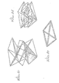
- FIGURE 1 shows a deployable truss structure constructed in accordance with the present invention comprised of two frame sections 101 and 102.
- FIGURE 1(a) shows the beam structure in its fully deployed state
- FIGURES 1(b) and 1(c) show the structure through mid-deployment stages to a fully collapsed state shown in FIGURE 1(d).
- the two sections 101 and 102 are mirror images of each other; section 101 will be described in detail.
- the section 101 has a quadrilateral cross section and has four longerons 12, 14, 16, and 18 extending along its longitudinal axis. The longerons define four faces of the section 101. Longerons 12 and 18 are connected to either end of a batten member 20.
- each face of the section 101 is bisected by a diagonal.
- FIGURE 1 shows one such face partially shaded to aid in visualizing the stages of deployment.
- FIGURE 1 shows a short column constructed of two structural units 101, 102. It is readily apparent that more than two such units 101, 102 could be used to construct a longer beam structure.
- longeron 12 is followed along the longitudinal axis of the structure by longeron member 112.
- longeron member 14 is associated with longeron member 114
- longeron member 16 is associated with longeron member 116
- longeron member 18 is associated with longeron member 118.
- the longeron members 112 through 118 are joined together by batten members 120, 122, 124, and 126, respectively.
- the two structural units 101, 102 "share" folding batten members 36, 38, 40, and 42.
- the diagonal members of one structural unit are located as "mirror images" of diagonal members of an associated structural unit.
- diagonal member 128 is located on the same quadrilateral face as diagonal member 28, and is joined at the folding batten member 36 at the same end as diagonal member 28.
- diagonal member 130 is associated with diagonal member 30
- diagonal member 132 is associated with diagonal member 32
- diagonal member 134 is associated with diagonal member 34.
- Other structural units could be added onto the structure 10 in order to create a columnar structure of much greater extent than that illustrated.
- FIGURE 2 shows a base hinge cluster that is used at the corners of the structure where the rigid batten members meet diagonal and longeron members.
- the hinge cluster includes a corner joint, which is provided with a plurality of flat projections. The ends of the longerons and diagonals are hinged with the flat projections.
- Each of the flat projections has a hole, as does the end of the frame member to be joined. The holes in the corner joint and the end of the frame member are aligned and a pin is inserted through the hole. In this way, the respective frame members are free to rotate relative to the hinge joint in the desired manner.
- Each of the hinge clusters used in the present invention is configured so as to allow a single degree of freedom during rotation.
- the diagonals rotate about an axis parallel to the batten members, while their longitudinal axis is inclined to the rotational axis. Therefore, the diagonal end that is hinged with the hinge joint is provided with a dog-leg bend, as shown in FIGURE 2 and FIGURE 3.
- the rigid batten member is also joined to the corner joint, adjacent the flat projections. As illustrated in FIGURE 2, the base hinge cluster only allows the longeron and diagonal member to rotate.
- the rigid batten members are fixed in position and do not rotate.
- FIGURE 3 shows a mid-structure hinge cluster at which longerons, diagonals, and folding batten members are joined.
- This hinge cluster is constructed similarly to the hinge cluster of FIGURE 2, expect that all frame members joined by the mid-structure hinge cluster rotate relatively to the hinge cluster. Once again, all rotation is through a single degree of freedom.
- FIGURE 3 shows a hinge joint 200 at which various members are pivotally connected.
- Joint 200 connects longeron members 12 and 112 to each other, joins folding batten members 36 and 38 together (forming a corner of the structure) and also connects associated diagonal members 28 and 128.
- folding batten members 36 and 38 will hinge outward at their midpoint hinges, away from the column structure, longeron members 12, 112 will pivot toward each other as illustrated in FIGURE 1(b), and diagonal members 28 and 128 will follow accordingly.
- FIGURE 4(a) shows a detail of a diagonal member 220 illustrating the configuration at the midpoint of the diagonal member with cut-out or trough portions 222 and 224 located on opposite sides of the diagonal member.
- This configuration is necessary because, upon collapsing the structure 10, the diagonal members will come to rest in a substantially coplanar fashion.
- a diagonal member 220 is laid on top of a similar diagonal member and perpendicular thereto with the trough portions facing each other, the two diagonal members will be substantially coplanar.
- diagonal member 220 can cross two other similar diagonal members in a perpendicular manner while still lying coplanar therewith.
- four similar diagonal members can cross perpendicularly to each other while lying flat.
- FIGURE 4(b) illustrates an arrangement of four diagonal members 220, 230, 240, 250 resting in interleaved, substantially coplanar fashion following collapse of the structure.
- the batten members and longerons are shown as being of equal length, such a configuration is not a requirement of the invention. It is also contemplated that certain durable, high strength materials may be used in producing a truss structure in accordance with the present invention.
- the hinges and joints may be constructed of stainless steel, and the frame members may be constructed of graphite epoxy composite tubing. Accordingly, the scope of the present invention should be considered in terms of the following claims, which are not to be limited to the details of the embodiment described and illustrated herein.
Abstract
Description
- This invention relates to truss structures and, more particularly, to collapsible truss structures desirable for space applications.
- Truss structures are desirable in space applications because they offer high strength and/or stiffness and low mass. External loads on trusses are reacted to by the truss members in pure tension or columnar compression. Such highly directed loading allows the use of uni-directional filamentary composite tubes as members, which have very high ratios of material stiffness-to-mass. The attendant truss property of repeating symmetry makes efficient packaging possible.
- The evolution of deployable space trusses has been toward greater performance in terms of high stiffness and low mass. For example, a deployable lattice column is described in U.S. Patent No. 3,486,279 to James E. Webb. Figure 7 thereof discloses a truss structure in which the longerons are comprised of continuous flexible rods. Thus, there are no hinges along the longerons and the full length of the longeron is utilized in terms of resisting collapse of the column, since the longerons maintain a tendency to spring back to a straight shape. The absence of longeron hinges results in a structure of low mass. The column, however, is limited in cross section because of strain in the packaged or collapsed condition. Hinging along the longerons would allow greater freedom in longeron member size, but hinge compliance would degrade member stiffness. Similar comments apply to U.S. Patent No. 4,532,742 to Koryo Miura, which discloses a similar structure employing continuous, flexible rods as longerons but adds spacers 2 along the longitudinal axis of the structure.
- The development of single-degree-of-freedom hinge technology has significantly reduced hinge compliance, and articulated structures have become viable. The structure disclosed in U.S. Patent No. 4,480,415 to Peter Truss, in which the longerons are arranged so as to form a triangular cross-section, includes longeron members that are formed from pairs of foldable rod members. Pressure directed at a longeron along the triangular face collapses the longeron. Disclosed in Figure 2 of the above-referenced patent to Webb is a deployable column in which the longerons do not fold, but in which the diagonals do collapse.
- Although single-degree-of-freedom hinges reduce hinge compliance, such hinges also introduce a problem: in general, packaging a truss structure using such hinges involves member strain during the transition from fully deployed to fully collapsed, even though either extreme is unstrained. As a result, force is required for deployment which depends on the degree of strain, and member sizing is limited to that which can survive the strain. Thus, there is a continuing need for improvements in truss structures for space applications that overcome the problems mentioned above.
- The present invention overcomes the above problems, and others, by providing a structural unit in which the longerons do not fold, the diagonals do not fold, and there is no deployment strain on the members. The non-folding longerons and diagonals minimize the number of hinges required so that compliance, as well as weight, is reduced. The lack of deployment strain allows the use of members of any stiffness and size.
- Strain that occurs during articulation of a hinged structure arises because of one or both of the following effects: (a) two hinges, which are associated because an articulating member connects them, change in angular orientation with respect to each other; (b) one of the two associated hinges moves along the axis of the other. In other words, the respective planes in which two hinges rotate change in terms of relative angle, or one hinge moves along the axis of the other, notwithstanding the presence of a connecting rod member. In the present invention, neither of these phenomena occur; that is, hinges which are associated do not change with respect to each other in position or orientation.
- The present invention may be used to construct a truss structure especially suited to space applications. The basic "building block" of the present invention consists of three rigid members that form a frame unit in the shape of a right triangle, the members being a longeron, a diagonal, and a batten. This frame unit does not change shape during packaging or during the transition from stowed to deployed condition and is connected to three other identical frames by connecting the rigid batten members end-to-end in a quadrilateral. The batten members so connected form a planar surface. The longeron and diagonal members are connected to their associated batten by hinges and pivot about an axis parallel to the batten member.
- An additional frame member is a folding batten, which completes the structure. The folding batten is hinged at its midpoint and is connected at one end to the corner of the frame where the longeron and diagonal meet and at the other end is connected to a neighboring frame unit (that is, another longeron-diagonal joint). In this way, the folding batten members combine with the longeron, diagonal, and rigid batten members in the deployed state to form a quadrilateral face of the structure. The folding batten members pivot about their mid-point hinges during the transition between the deployed condition and collapsed condition. The hinges at the mid-point of the folding batten rotate about an axis parallel to the deployed truss structure longitudinal axis, perpendicular to the plane formed by the four rigid batten members. During the transition between the stowed and deployed conditions, the folding batten axis of rotation remains perpendicular to the rigid batten plane, in keeping with the lack of member strain characteristic of the present invention.
- A truss beam structure may be assembled using a plurality of such structural units connected together such that the longerons extend along the longitudinal axis of the beam structure, while the battens extend perpendicular to the longerons and the diagonals brace the longerons and battens. Thus, the present invention discloses a structure in which the load-carrying members (longerons and diagonals) do not fold, but yet may be stowed into a compact package. Additionally, deployment does not cause member strain, allowing more freedom in choosing member size and composition and providing a rigid, low-mass structure.
- The present invention is able to combine rigid structural elements with the articulation necessary to compactly collapse the structure through the use of the unique hinge clusters provided, which allow the structure to collapse into a compact size and still utilize members that do not fold. The hinge clusters include corner joints and frame member end pieces that allow the various frame members to meet at the desired angles and still rotate between collapsed and deployed conditions with a single degree of freedom.
- The novel features that are believed to be characteristic of the present invention, both as to its organization and method of operation, together with further objectives and advantages thereof, will be better understood from the following description considered in connection with the accompanying drawings in which a presently preferred embodiment of the invention is illustrated by way of example. It is to be expressly understood, however, that the drawings are for the purpose of illustration and description only and are not intended as a definition of the limits of the invention.
-
- FIGURE 1 shows a perspective view of a column structure in accordance with a preferred embodiment of he present invention from a fully deployed state through mid-deployment stages to a fully collapsed state.
- FIGURE 2 shows a perspective view of a base hinge cluster used to join various structural members.
- FIGURE 3 shows a perspective view of a mid-structure hinge cluster used to join various structural members.
- FIGURE 4 shows further detail of the diagonal members of FIGURE 1(a).
- FIGURE 1 shows a deployable truss structure constructed in accordance with the present invention comprised of two
frame sections sections section 101 will be described in detail. Thesection 101 has a quadrilateral cross section and has fourlongerons section 101. Longerons 12 and 18 are connected to either end of abatten member 20. The other longerons are similarly connected withbatten members diagonal member 28braces longeron member 12 andbatten member 20 by extending between the ends of thelongeron 12 andbatten 20 that are not joined. Similarly,diagonal member 30 extends betweenlongeron member 14 andbatten member 22,diagonal member 32 extends betweenlongeron 16 andbatten 24, anddiagonal 34 extends betweenlongeron 18 andbatten 26. Thus, each face of thesection 101 is bisected by a diagonal. FIGURE 1 shows one such face partially shaded to aid in visualizing the stages of deployment. - Completing the frame section are four folding batten
members members structural units such units longeron 12 is followed along the longitudinal axis of the structure bylongeron member 112. Likewise,longeron member 14 is associated withlongeron member 114,longeron member 16 is associated withlongeron member 116, andlongeron member 18 is associated withlongeron member 118. Furthermore, thelongeron members 112 through 118 are joined together by battenmembers structural units members diagonal member 128 is located on the same quadrilateral face asdiagonal member 28, and is joined at the folding battenmember 36 at the same end asdiagonal member 28. Likewise,diagonal member 130 is associated withdiagonal member 30,diagonal member 132 is associated withdiagonal member 32, anddiagonal member 134 is associated withdiagonal member 34. Other structural units could be added onto the structure 10 in order to create a columnar structure of much greater extent than that illustrated. - FIGURE 2 shows a base hinge cluster that is used at the corners of the structure where the rigid batten members meet diagonal and longeron members. The hinge cluster includes a corner joint, which is provided with a plurality of flat projections. The ends of the longerons and diagonals are hinged with the flat projections. Each of the flat projections has a hole, as does the end of the frame member to be joined. The holes in the corner joint and the end of the frame member are aligned and a pin is inserted through the hole. In this way, the respective frame members are free to rotate relative to the hinge joint in the desired manner. Each of the hinge clusters used in the present invention is configured so as to allow a single degree of freedom during rotation. For example, the diagonals rotate about an axis parallel to the batten members, while their longitudinal axis is inclined to the rotational axis. Therefore, the diagonal end that is hinged with the hinge joint is provided with a dog-leg bend, as shown in FIGURE 2 and FIGURE 3. The rigid batten member is also joined to the corner joint, adjacent the flat projections. As illustrated in FIGURE 2, the base hinge cluster only allows the longeron and diagonal member to rotate. The rigid batten members are fixed in position and do not rotate.
- FIGURE 3 shows a mid-structure hinge cluster at which longerons, diagonals, and folding batten members are joined. This hinge cluster is constructed similarly to the hinge cluster of FIGURE 2, expect that all frame members joined by the mid-structure hinge cluster rotate relatively to the hinge cluster. Once again, all rotation is through a single degree of freedom.
- FIGURE 3 shows a hinge joint 200 at which various members are pivotally connected.
Joint 200 connectslongeron members members diagonal members members longeron members diagonal members - FIGURE 4(a) shows a detail of a
diagonal member 220 illustrating the configuration at the midpoint of the diagonal member with cut-out ortrough portions diagonal member 220 is laid on top of a similar diagonal member and perpendicular thereto with the trough portions facing each other, the two diagonal members will be substantially coplanar. In this way,diagonal member 220 can cross two other similar diagonal members in a perpendicular manner while still lying coplanar therewith. Thus, four similar diagonal members can cross perpendicularly to each other while lying flat. FIGURE 4(b) illustrates an arrangement of fourdiagonal members - Although a particular embodiment of the present invention has been described and illustrated herein, modifications and variations may be readily apparent to those skilled in the art. For example, although the batten members and longerons are shown as being of equal length, such a configuration is not a requirement of the invention. It is also contemplated that certain durable, high strength materials may be used in producing a truss structure in accordance with the present invention. For example, the hinges and joints may be constructed of stainless steel, and the frame members may be constructed of graphite epoxy composite tubing. Accordingly, the scope of the present invention should be considered in terms of the following claims, which are not to be limited to the details of the embodiment described and illustrated herein.
- The features disclosed in the foregoing description, or the following claims, or the accompanying drawings, expressed in their specific forms or in terms of a means for performing the disclosed function, or a method or process for attaining the disclosed result, as appropriate, may, separately or in any combination of such features, be utilised for realising the invention in diverse forms thereof.
Claims (7)
at least one frame unit, each frame unit comprised of four rigid, elongate batten, longeron, and diagonal members, and four folding batten members,
the four rigid batten members being connected at their end points so as to form a quadrilateral,
each longeron being pivotally connected at a first end to an associated rigid batten member at each corner of the quadrilateral such that each longeron pivots about an axis parallel to the longitudinal axis of the associated rigid batten member and such that, in the deployed position, each longeron is perpendicular to the plane defined by the quadrilateral,
each diagonal being connected to the free ends of an associated longeron, and to the free end of the rigid batten member associated with said associated longeron, each diagonal being pivotally connected at the rigid batten member such that the diagonal rotates about the same axis as the longeron, and having two trough portions located opposite and adjacent to each other at approximately the midpoint of the diagonal;
the folding batten elements being hinged at their midpoint about an axis perpendicular to the face of the quadrilateral and pivotally connected at their ends to the junction of a diagonal and longeron such that the folding batten elements pivot during the transition between collapsed and deployed positions of the truss structure.
at least one structural unit comprised of four frame units, each frame unit comprised of three elongate members forming a right triangle, a first leg of each frame unit being connected to a first leg of another frame unit so that the connected first legs form a rigid quadrilateral, the remaining second leg and hypotenuse of each frame unit being pivotally connected to the first leg so as to pivot about an axis parallel to the longitudinal axis of the first leg, the hypotenuse having two trough portions located opposite and adjacent each other at the midpoint of the hypotenuse longitudinal axis; and
at least four folding batten elements, hinged at their midpoints about an axis perpendicular to their longitudinal axis and pivotally connected at their ends to the frame units such that the frame units pivot toward the interior of the quadrilateral so as to move between the deployed position, in which the frame units are perpendicular to the plane defined by the quadrilateral, and the collapsed position, in which the frame units lie in a plane parallel to the quadrilateral.
Applications Claiming Priority (2)
| Application Number | Priority Date | Filing Date | Title |
|---|---|---|---|
| US42162 | 1987-04-23 | ||
| US4216287A | 1987-04-24 | 1987-04-24 |
Publications (3)
| Publication Number | Publication Date |
|---|---|
| EP0288323A2 true EP0288323A2 (en) | 1988-10-26 |
| EP0288323A3 EP0288323A3 (en) | 1989-05-24 |
| EP0288323B1 EP0288323B1 (en) | 1993-02-03 |
Family
ID=21920367
Family Applications (1)
| Application Number | Title | Priority Date | Filing Date |
|---|---|---|---|
| EP88303714A Expired - Lifetime EP0288323B1 (en) | 1987-04-23 | 1988-04-25 | Collapsible structure |
Country Status (5)
| Country | Link |
|---|---|
| US (1) | US5163262A (en) |
| EP (1) | EP0288323B1 (en) |
| JP (1) | JPS63280000A (en) |
| CA (1) | CA1310165C (en) |
| DE (1) | DE3878013T2 (en) |
Cited By (3)
| Publication number | Priority date | Publication date | Assignee | Title |
|---|---|---|---|---|
| US4964597A (en) * | 1989-03-15 | 1990-10-23 | Yousef Hijazi | Space vehicle with collapsible living quarters |
| US9938720B2 (en) | 2013-11-04 | 2018-04-10 | Ipi Access As | Support structure module and modular beam structure |
| EP4234416A1 (en) * | 2022-02-24 | 2023-08-30 | David Anthony Nixon | Expandable structural modules for toroidal space station structures, space station substructures, toroidal space station structures, and methods of constructing toroidal space station structures |
Families Citing this family (54)
| Publication number | Priority date | Publication date | Assignee | Title |
|---|---|---|---|---|
| NL9401355A (en) * | 1994-08-22 | 1996-04-01 | Laarhoven Design Int | Folding and folding frame. |
| US5819492A (en) * | 1995-07-17 | 1998-10-13 | Konicek; Richard R. | Collapsible roof truss utilizing an opposed flange roof hinge |
| US5845451A (en) * | 1996-01-31 | 1998-12-08 | Tolentino; Edgar Williams | Telescoping polygonal figure |
| US5701713A (en) * | 1996-03-29 | 1997-12-30 | Silver; Daniel J. | Adjustable truss |
| US5826384A (en) * | 1996-11-12 | 1998-10-27 | Lucasey Manufacturing Company | Modular truss system |
| US5896718A (en) * | 1996-11-25 | 1999-04-27 | Westgarth; Peter | Collapsible panel and modular enclosure and partition system |
| US5826397A (en) * | 1997-03-25 | 1998-10-27 | Armold; Charles K. | Collapsible framework for trade show display |
| US6076770A (en) * | 1998-06-29 | 2000-06-20 | Lockheed Martin Corporation | Folding truss |
| US6062527A (en) * | 1998-06-29 | 2000-05-16 | Lockheed Martin Corporation | Flexurally hinged tripod support boom |
| US6038736A (en) * | 1998-06-29 | 2000-03-21 | Lockheed Martin Corporation | Hinge for deployable truss |
| US6313811B1 (en) | 1999-06-11 | 2001-11-06 | Harris Corporation | Lightweight, compactly deployable support structure |
| US6618025B2 (en) | 1999-06-11 | 2003-09-09 | Harris Corporation | Lightweight, compactly deployable support structure with telescoping members |
| US8074324B2 (en) | 1999-11-09 | 2011-12-13 | Foster-Miller, Inc. | Flexible, deployment rate damped hinge |
| US6904722B2 (en) * | 2001-02-21 | 2005-06-14 | The United States Of America As Represented By The Secretary Of The Navy | Elongated truss boom structures for space applications |
| US7028442B2 (en) * | 2001-07-03 | 2006-04-18 | Merrifield Donald V | Deployable truss beam with orthogonally-hinged folding diagonals |
| US6910304B2 (en) | 2002-04-02 | 2005-06-28 | Foster-Miller, Inc. | Stiffener reinforced foldable member |
| US20060117700A1 (en) * | 2004-11-24 | 2006-06-08 | Wagner Richard J | Double knee jointed longeron truss for space structures |
| DE602004018360D1 (en) * | 2004-12-28 | 2009-01-22 | Alcatel Lucent | Connecting device for space equipment elements with flexible deployable blades |
| US7979981B2 (en) | 2005-05-23 | 2011-07-19 | Innovequity Inc. | Automated construction system |
| US7963084B2 (en) | 2005-08-29 | 2011-06-21 | Donald Merrifield | Deployable triangular truss beam with orthogonally-hinged folding diagonals |
| US7617639B1 (en) * | 2006-08-08 | 2009-11-17 | The United States Of America As Represented By The Secretary Of The Air Force | Tape-spring deployable boom |
| US7941978B1 (en) * | 2006-08-10 | 2011-05-17 | The United States Of America As Represented By The Secretary Of The Air Force | Deployable heirarchical structure |
| US8011162B2 (en) * | 2006-09-28 | 2011-09-06 | Christopher Clint Overby | Chain constructed structure |
| US20080283670A1 (en) * | 2006-12-13 | 2008-11-20 | Thomas Jeffrey Harvey | K-truss deployable boom system |
| DE102006060347B4 (en) * | 2006-12-20 | 2008-09-25 | Liebherr-Werk Ehingen Gmbh | Lattice piece for a mobile large crane and method for its erection |
| US20080263995A1 (en) * | 2007-04-27 | 2008-10-30 | Innovequity Inc. | Automated construction system with interlocking panels |
| JP5172453B2 (en) * | 2008-04-25 | 2013-03-27 | シャープ株式会社 | Solar cell blanket and solar cell paddle using the same |
| US7992353B2 (en) * | 2008-12-10 | 2011-08-09 | Athan Stephan P | Space frame hub joint |
| DE102008063214B3 (en) * | 2008-12-29 | 2010-11-25 | Novacki, Zoran, Dipl.-Ing. | Movable support structure for e.g. mobile crane, has modular unit with telescoping wing-shaped elements, and tensile connection provided between coupling joints of three-arm component |
| EP2272761A1 (en) * | 2009-06-18 | 2011-01-12 | Astrium Limited | Extendable structure |
| DE202010011131U1 (en) * | 2010-08-06 | 2011-11-23 | Liebherr-Werk Ehingen Gmbh | Lattice piece and crane |
| US8689514B1 (en) * | 2011-05-04 | 2014-04-08 | Softronics, Ltd. | Expandable structure |
| CN202283150U (en) * | 2011-09-28 | 2012-06-27 | 临海市远帆旅游制品有限公司 | Foldable flower holder |
| US9555871B2 (en) * | 2012-03-05 | 2017-01-31 | The Boeing Company | Two-surface sandwich structure for accommodating in-plane expansion of one of the surfaces relative to the opposing surface |
| US8905054B2 (en) * | 2012-09-20 | 2014-12-09 | EZ as a Drink Productions, Inc. | Protrusive structure apparatus |
| USD707473S1 (en) | 2012-09-28 | 2014-06-24 | Worldwide Creations, LLC | Collapsible enclosure |
| USD722795S1 (en) | 2012-09-28 | 2015-02-24 | Worldwide Creations, LLC | Collapsible enclosure |
| USD707472S1 (en) | 2012-09-28 | 2014-06-24 | Worldwide Creations, LLC | Collapsible enclosure |
| ITNO20130004A1 (en) * | 2013-06-03 | 2014-12-04 | Mauro Sica | PARTICULARLY PREASSEMBLY PRE-DISTANCE SYSTEM FOR THE ELEMENTS OF A STRUCTURAL FRAME |
| US10231538B2 (en) | 2013-08-08 | 2019-03-19 | Rehrig Pacific Company | Collapsible shelving unit |
| US9198508B1 (en) * | 2013-08-30 | 2015-12-01 | Gary W Kufel | Portable, compact, and collapsible shelving unit |
| BR112016029232B1 (en) * | 2014-07-01 | 2022-05-03 | Dsm Ip Assets B.V. | Structure comprising rigid elements linked together through interconnecting elements and use of polymeric fiber comprising ultra-high molecular weight polyethylene |
| US9828772B2 (en) * | 2015-06-11 | 2017-11-28 | L'garde, Inc. | Truss designs, materials, and fabrication |
| JP6141957B1 (en) * | 2015-12-25 | 2017-06-07 | 日本飛行機株式会社 | Extension mast feeding device |
| US9668600B1 (en) * | 2016-01-12 | 2017-06-06 | Ka Wai Lau | Multi-level serving tray carrier |
| US10957987B2 (en) * | 2016-07-14 | 2021-03-23 | Harris Corporation | Space deployable inflatable antenna apparatus and associated methods |
| US10465373B2 (en) | 2016-07-28 | 2019-11-05 | Cole David Kazuyuki TURNER | Integrated structural member |
| GB2555657A (en) * | 2016-11-08 | 2018-05-09 | Oxford Space Systems | Deployable mast structure |
| US10119266B1 (en) * | 2016-12-22 | 2018-11-06 | The Government Of The United States Of America As Represented By The Secretary Of The Air Force | Extensible sparse-isogrid column |
| US10113330B2 (en) * | 2017-03-21 | 2018-10-30 | Imam Abdulrahman Bin Faisal University | Expandable mat-based sun shelter |
| US11028895B2 (en) * | 2017-09-25 | 2021-06-08 | University Of Washington | Shock absorbing and impact mitigating structures based on axial-rotational coupling mechanism |
| CN109577489A (en) * | 2018-12-26 | 2019-04-05 | 佛山科学技术学院 | A kind of folding girder steel and a kind of folding building enclosure |
| CN110065653B (en) * | 2019-05-23 | 2020-08-04 | 上海微小卫星工程中心 | Main framework of small high-orbit satellite common platform |
| CN117585311A (en) * | 2022-08-17 | 2024-02-23 | 广东美的白色家电技术创新中心有限公司 | Force transmission structure, packaging assembly, electrical assembly, filter screen and electrical equipment |
Citations (3)
| Publication number | Priority date | Publication date | Assignee | Title |
|---|---|---|---|---|
| US3486279A (en) * | 1967-11-30 | 1969-12-30 | Nasa | Deployable lattice column |
| US4599832A (en) * | 1985-01-04 | 1986-07-15 | Benton Max D | Extendible structures |
| US4655022A (en) * | 1984-07-12 | 1987-04-07 | Japan Aircraft Mfg. Co., Ltd. | Jointed extendible truss beam |
Family Cites Families (32)
| Publication number | Priority date | Publication date | Assignee | Title |
|---|---|---|---|---|
| US415667A (en) * | 1889-11-19 | edwards- | ||
| US2301077A (en) * | 1942-05-20 | 1942-11-03 | Bradley Mfg Company | Lever for loom box lifting mechanism |
| US3053351A (en) * | 1960-02-19 | 1962-09-11 | Junius H Fulcher | Structural device |
| US3521421A (en) * | 1968-01-02 | 1970-07-21 | William E Schroeder Jr | Geodesic structure |
| IT944988B (en) * | 1970-11-20 | 1973-04-20 | Creative Eng Ltd | IMPROVEMENT IN EXTENSIBLE STRUCTURES IN PARTICULAR TOWERS FOR WORKS IN ELEVATED AND SIMILAR LOCATIONS |
| US3757476A (en) * | 1970-12-17 | 1973-09-11 | Nasa | Expandable space-frames |
| FR2138244B1 (en) * | 1971-05-19 | 1973-05-11 | Soisson Gerard | |
| US3783573A (en) * | 1972-12-07 | 1974-01-08 | Gen Dynamics Corp | Expandable truss structure |
| US4115975A (en) * | 1977-08-11 | 1978-09-26 | University Of Utah | Foldable/extensible structure |
| US4332501A (en) * | 1978-08-03 | 1982-06-01 | General Dynamics Corporation | Structural node for large space structures |
| US4276726A (en) * | 1979-12-17 | 1981-07-07 | Derus David L | Collapsable, articulated wall structure |
| US4334391A (en) * | 1980-04-21 | 1982-06-15 | Astro Research Corporation | Redundant deployable lattice column |
| FR2487133A1 (en) * | 1980-07-18 | 1982-01-22 | Europ Agence Spatiale | Foldable mast for automatic lunar vehicle - has vertically opposing frames interconnected by hinged struts which are tensioned in unfolded attitude by cables |
| DE3222475A1 (en) * | 1981-06-19 | 1983-01-27 | British Aerospace Public Ltd. Co., London | EXTENDABLE MASTER STRUCTURE |
| US4524552A (en) * | 1981-10-09 | 1985-06-25 | General Dynamics Corporation/Convair Div. | Mechanism for deploying a deployable truss beam |
| US4482900A (en) * | 1982-09-13 | 1984-11-13 | The United States Of America As Represented By The Secretary Of The Air Force | Deployable folded antenna apparatus |
| EP0106270B1 (en) * | 1982-10-09 | 1987-08-12 | Mitsubishi Denki Kabushiki Kaisha | Extendible structure |
| US4539786A (en) * | 1983-03-03 | 1985-09-10 | Ltv Aerospace And Defense Co. | Biaxial scissors fold, post tensioned structure |
| US4557097A (en) * | 1983-09-08 | 1985-12-10 | The United States Of America As Represented By The Administrator Of The National Aeronautics And Space Administration | Sequentially deployable maneuverable tetrahedral beam |
| US4569176A (en) * | 1983-11-28 | 1986-02-11 | Astro Research Corporation | Rigid diagonal deployable lattice column |
| US4819399A (en) * | 1984-10-12 | 1989-04-11 | Hitachi, Ltd. | Deployable truss |
| JPH0615783B2 (en) * | 1985-07-25 | 1994-03-02 | 淳次郎 小野田 | Deployed structure |
| US4677803A (en) * | 1986-02-20 | 1987-07-07 | The United States Of America As Represented By The Administrator Of The National Aeronautics And Space Administration | Deployable geodesic truss structure |
| JPH0742812B2 (en) * | 1986-06-04 | 1995-05-10 | 富士重工業株式会社 | Deployed structure |
| US4679961A (en) * | 1986-06-16 | 1987-07-14 | Lockheed Missiles & Space Company, Inc. | Coupling mechanism |
| US5016418A (en) * | 1986-08-22 | 1991-05-21 | The United States Of America As Represented By The Administrator Of The National Aeronautics And Space Administration | Synchronously deployable double fold beam and planar truss structure |
| JPH0631080B2 (en) * | 1987-03-31 | 1994-04-27 | 日本飛行機株式会社 | Extension structure |
| US5094046A (en) * | 1989-01-05 | 1992-03-10 | Astro Aerospace | Deployable mast |
| JPH05307451A (en) * | 1992-04-30 | 1993-11-19 | Hokuriku Nippon Denki Software Kk | Print output control system |
| JPH07160448A (en) * | 1993-12-06 | 1995-06-23 | Canon Inc | Printing system |
| JPH07200205A (en) * | 1993-12-28 | 1995-08-04 | Fuji Xerox Co Ltd | Printing device |
| JP2828011B2 (en) * | 1996-03-22 | 1998-11-25 | 日本電気株式会社 | Printer device |
-
1988
- 1988-04-22 CA CA000564807A patent/CA1310165C/en not_active Expired - Fee Related
- 1988-04-25 EP EP88303714A patent/EP0288323B1/en not_active Expired - Lifetime
- 1988-04-25 DE DE8888303714T patent/DE3878013T2/en not_active Expired - Fee Related
- 1988-04-25 JP JP63102348A patent/JPS63280000A/en active Pending
-
1990
- 1990-02-26 US US07/484,490 patent/US5163262A/en not_active Expired - Lifetime
Patent Citations (3)
| Publication number | Priority date | Publication date | Assignee | Title |
|---|---|---|---|---|
| US3486279A (en) * | 1967-11-30 | 1969-12-30 | Nasa | Deployable lattice column |
| US4655022A (en) * | 1984-07-12 | 1987-04-07 | Japan Aircraft Mfg. Co., Ltd. | Jointed extendible truss beam |
| US4599832A (en) * | 1985-01-04 | 1986-07-15 | Benton Max D | Extendible structures |
Cited By (3)
| Publication number | Priority date | Publication date | Assignee | Title |
|---|---|---|---|---|
| US4964597A (en) * | 1989-03-15 | 1990-10-23 | Yousef Hijazi | Space vehicle with collapsible living quarters |
| US9938720B2 (en) | 2013-11-04 | 2018-04-10 | Ipi Access As | Support structure module and modular beam structure |
| EP4234416A1 (en) * | 2022-02-24 | 2023-08-30 | David Anthony Nixon | Expandable structural modules for toroidal space station structures, space station substructures, toroidal space station structures, and methods of constructing toroidal space station structures |
Also Published As
| Publication number | Publication date |
|---|---|
| DE3878013D1 (en) | 1993-03-18 |
| US5163262A (en) | 1992-11-17 |
| CA1310165C (en) | 1992-11-17 |
| DE3878013T2 (en) | 1993-05-19 |
| EP0288323A3 (en) | 1989-05-24 |
| EP0288323B1 (en) | 1993-02-03 |
| JPS63280000A (en) | 1988-11-17 |
Similar Documents
| Publication | Publication Date | Title |
|---|---|---|
| US5163262A (en) | Collapsible structure | |
| US5040349A (en) | Collapsible truss structures | |
| US4958474A (en) | Truss structure | |
| CA1271014A (en) | Collapsible truss unit, and frameworks constructed by combinations of such units | |
| JP2625255B2 (en) | Scissor end captured collapsible canopy framework with incompressible pivot | |
| US6173726B1 (en) | Erectable shelter including a collapsible truss | |
| US4655022A (en) | Jointed extendible truss beam | |
| US3672104A (en) | Nesting three dimensional lazy tong structure | |
| US7716897B2 (en) | Deployable rectangular truss beam with orthogonally-hinged folding diagonals | |
| US5701713A (en) | Adjustable truss | |
| EP0290729B1 (en) | Module for expandable truss structure and expandable truss structure employing said module | |
| WO2002063111A1 (en) | Loop assemblies having a central link | |
| EP0249307B1 (en) | Collapsible truss unit for use in combination with other like units for the construction of frameworks | |
| US4074477A (en) | Modular building structure | |
| EP0293109B1 (en) | Truss structure | |
| US7941978B1 (en) | Deployable heirarchical structure | |
| JP3540161B2 (en) | Variable shape truss frame | |
| JPH03151477A (en) | Spreading mast | |
| JPH0632293A (en) | Development type truss | |
| JPH0416651A (en) | Loop assembly | |
| AU618046B2 (en) | Collapsible shelter | |
| JP2553241B2 (en) | Deployable static definite truss structure | |
| CA1279971C (en) | Collapsible truss unit for use in combination with other like units for the constructions of frameworks | |
| CN112912571A (en) | Frame and system for interconnecting frames | |
| JPH05270499A (en) | Two-dimensional development truss |
Legal Events
| Date | Code | Title | Description |
|---|---|---|---|
| PUAI | Public reference made under article 153(3) epc to a published international application that has entered the european phase |
Free format text: ORIGINAL CODE: 0009012 |
|
| AK | Designated contracting states |
Kind code of ref document: A2 Designated state(s): DE FR GB NL |
|
| PUAL | Search report despatched |
Free format text: ORIGINAL CODE: 0009013 |
|
| AK | Designated contracting states |
Kind code of ref document: A3 Designated state(s): DE FR GB NL |
|
| 17P | Request for examination filed |
Effective date: 19891123 |
|
| 17Q | First examination report despatched |
Effective date: 19910328 |
|
| GRAA | (expected) grant |
Free format text: ORIGINAL CODE: 0009210 |
|
| AK | Designated contracting states |
Kind code of ref document: B1 Designated state(s): DE FR GB NL |
|
| PG25 | Lapsed in a contracting state [announced via postgrant information from national office to epo] |
Ref country code: NL Effective date: 19930203 Ref country code: FR Effective date: 19930203 |
|
| REF | Corresponds to: |
Ref document number: 3878013 Country of ref document: DE Date of ref document: 19930318 |
|
| PG25 | Lapsed in a contracting state [announced via postgrant information from national office to epo] |
Ref country code: GB Effective date: 19930503 |
|
| EN | Fr: translation not filed | ||
| NLV1 | Nl: lapsed or annulled due to failure to fulfill the requirements of art. 29p and 29m of the patents act | ||
| PLBE | No opposition filed within time limit |
Free format text: ORIGINAL CODE: 0009261 |
|
| STAA | Information on the status of an ep patent application or granted ep patent |
Free format text: STATUS: NO OPPOSITION FILED WITHIN TIME LIMIT |
|
| PG25 | Lapsed in a contracting state [announced via postgrant information from national office to epo] |
Ref country code: DE Effective date: 19940101 |
|
| GBPC | Gb: european patent ceased through non-payment of renewal fee |
Effective date: 19930503 |
|
| 26N | No opposition filed |