EP0287986B1 - Punching device for thin plates and punching units used with punching device - Google Patents
Punching device for thin plates and punching units used with punching device Download PDFInfo
- Publication number
- EP0287986B1 EP0287986B1 EP88106132A EP88106132A EP0287986B1 EP 0287986 B1 EP0287986 B1 EP 0287986B1 EP 88106132 A EP88106132 A EP 88106132A EP 88106132 A EP88106132 A EP 88106132A EP 0287986 B1 EP0287986 B1 EP 0287986B1
- Authority
- EP
- European Patent Office
- Prior art keywords
- punching
- punch
- accordance
- workpiece
- punching device
- Prior art date
- Legal status (The legal status is an assumption and is not a legal conclusion. Google has not performed a legal analysis and makes no representation as to the accuracy of the status listed.)
- Expired - Lifetime
Links
- 238000004080 punching Methods 0.000 title claims description 192
- 230000007246 mechanism Effects 0.000 claims description 38
- 238000000034 method Methods 0.000 claims description 10
- 229910000831 Steel Inorganic materials 0.000 claims description 4
- 230000004044 response Effects 0.000 claims description 4
- 239000010959 steel Substances 0.000 claims description 4
- 238000003780 insertion Methods 0.000 description 5
- 230000037431 insertion Effects 0.000 description 5
- 239000000463 material Substances 0.000 description 4
- 230000000694 effects Effects 0.000 description 3
- 230000009471 action Effects 0.000 description 2
- 230000000712 assembly Effects 0.000 description 2
- 238000000429 assembly Methods 0.000 description 2
- 230000000295 complement effect Effects 0.000 description 2
- 239000011888 foil Substances 0.000 description 2
- 238000012423 maintenance Methods 0.000 description 2
- 238000005452 bending Methods 0.000 description 1
- 230000008859 change Effects 0.000 description 1
- 210000000078 claw Anatomy 0.000 description 1
- 238000004891 communication Methods 0.000 description 1
- 238000002347 injection Methods 0.000 description 1
- 239000007924 injection Substances 0.000 description 1
- 238000009434 installation Methods 0.000 description 1
- 230000004048 modification Effects 0.000 description 1
- 238000012986 modification Methods 0.000 description 1
- 230000000717 retained effect Effects 0.000 description 1
- 229920002379 silicone rubber Polymers 0.000 description 1
- 239000007787 solid Substances 0.000 description 1
Images


Classifications
-
- B—PERFORMING OPERATIONS; TRANSPORTING
- B26—HAND CUTTING TOOLS; CUTTING; SEVERING
- B26D—CUTTING; DETAILS COMMON TO MACHINES FOR PERFORATING, PUNCHING, CUTTING-OUT, STAMPING-OUT OR SEVERING
- B26D7/00—Details of apparatus for cutting, cutting-out, stamping-out, punching, perforating, or severing by means other than cutting
- B26D7/26—Means for mounting or adjusting the cutting member; Means for adjusting the stroke of the cutting member
- B26D7/2628—Means for adjusting the position of the cutting member
-
- B—PERFORMING OPERATIONS; TRANSPORTING
- B26—HAND CUTTING TOOLS; CUTTING; SEVERING
- B26F—PERFORATING; PUNCHING; CUTTING-OUT; STAMPING-OUT; SEVERING BY MEANS OTHER THAN CUTTING
- B26F1/00—Perforating; Punching; Cutting-out; Stamping-out; Apparatus therefor
- B26F1/02—Perforating by punching, e.g. with relatively-reciprocating punch and bed
- B26F1/04—Perforating by punching, e.g. with relatively-reciprocating punch and bed with selectively-operable punches
-
- H—ELECTRICITY
- H05—ELECTRIC TECHNIQUES NOT OTHERWISE PROVIDED FOR
- H05K—PRINTED CIRCUITS; CASINGS OR CONSTRUCTIONAL DETAILS OF ELECTRIC APPARATUS; MANUFACTURE OF ASSEMBLAGES OF ELECTRICAL COMPONENTS
- H05K13/00—Apparatus or processes specially adapted for manufacturing or adjusting assemblages of electric components
- H05K13/0015—Orientation; Alignment; Positioning
-
- H—ELECTRICITY
- H05—ELECTRIC TECHNIQUES NOT OTHERWISE PROVIDED FOR
- H05K—PRINTED CIRCUITS; CASINGS OR CONSTRUCTIONAL DETAILS OF ELECTRIC APPARATUS; MANUFACTURE OF ASSEMBLAGES OF ELECTRICAL COMPONENTS
- H05K3/00—Apparatus or processes for manufacturing printed circuits
- H05K3/0011—Working of insulating substrates or insulating layers
- H05K3/0044—Mechanical working of the substrate, e.g. drilling or punching
- H05K3/005—Punching of holes
-
- B—PERFORMING OPERATIONS; TRANSPORTING
- B26—HAND CUTTING TOOLS; CUTTING; SEVERING
- B26F—PERFORATING; PUNCHING; CUTTING-OUT; STAMPING-OUT; SEVERING BY MEANS OTHER THAN CUTTING
- B26F2210/00—Perforating, punching, cutting-out, stamping-out, severing by means other than cutting of specific products
- B26F2210/08—Perforating, punching, cutting-out, stamping-out, severing by means other than cutting of specific products of ceramic green sheets, printed circuit boards and the like
-
- Y—GENERAL TAGGING OF NEW TECHNOLOGICAL DEVELOPMENTS; GENERAL TAGGING OF CROSS-SECTIONAL TECHNOLOGIES SPANNING OVER SEVERAL SECTIONS OF THE IPC; TECHNICAL SUBJECTS COVERED BY FORMER USPC CROSS-REFERENCE ART COLLECTIONS [XRACs] AND DIGESTS
- Y10—TECHNICAL SUBJECTS COVERED BY FORMER USPC
- Y10T—TECHNICAL SUBJECTS COVERED BY FORMER US CLASSIFICATION
- Y10T83/00—Cutting
- Y10T83/162—With control means responsive to replaceable or selectable information program
- Y10T83/173—Arithmetically determined program
-
- Y—GENERAL TAGGING OF NEW TECHNOLOGICAL DEVELOPMENTS; GENERAL TAGGING OF CROSS-SECTIONAL TECHNOLOGIES SPANNING OVER SEVERAL SECTIONS OF THE IPC; TECHNICAL SUBJECTS COVERED BY FORMER USPC CROSS-REFERENCE ART COLLECTIONS [XRACs] AND DIGESTS
- Y10—TECHNICAL SUBJECTS COVERED BY FORMER USPC
- Y10T—TECHNICAL SUBJECTS COVERED BY FORMER US CLASSIFICATION
- Y10T83/00—Cutting
- Y10T83/869—Means to drive or to guide tool
- Y10T83/8727—Plural tools selectively engageable with single drive
- Y10T83/8729—Predetermined sequence of selection
- Y10T83/873—Of paired tools
-
- Y—GENERAL TAGGING OF NEW TECHNOLOGICAL DEVELOPMENTS; GENERAL TAGGING OF CROSS-SECTIONAL TECHNOLOGIES SPANNING OVER SEVERAL SECTIONS OF THE IPC; TECHNICAL SUBJECTS COVERED BY FORMER USPC CROSS-REFERENCE ART COLLECTIONS [XRACs] AND DIGESTS
- Y10—TECHNICAL SUBJECTS COVERED BY FORMER USPC
- Y10T—TECHNICAL SUBJECTS COVERED BY FORMER US CLASSIFICATION
- Y10T83/00—Cutting
- Y10T83/869—Means to drive or to guide tool
- Y10T83/8759—With means to connect or disconnect tool and its drive
-
- Y—GENERAL TAGGING OF NEW TECHNOLOGICAL DEVELOPMENTS; GENERAL TAGGING OF CROSS-SECTIONAL TECHNOLOGIES SPANNING OVER SEVERAL SECTIONS OF THE IPC; TECHNICAL SUBJECTS COVERED BY FORMER USPC CROSS-REFERENCE ART COLLECTIONS [XRACs] AND DIGESTS
- Y10—TECHNICAL SUBJECTS COVERED BY FORMER USPC
- Y10T—TECHNICAL SUBJECTS COVERED BY FORMER US CLASSIFICATION
- Y10T83/00—Cutting
- Y10T83/869—Means to drive or to guide tool
- Y10T83/8821—With simple rectilinear reciprocating motion only
- Y10T83/8858—Fluid pressure actuated
Definitions
- the present invention generally relates to a punching device for punching out pieces from thin plate material and methods of punching, as known from US-A-4 653 365.
- Conventional punching devices used for punching holes having round, rectangular or ovular shapes exist for making the holes in desired locations in thin plate material, e.g. in circuit boards, flexible films, or metallic foil; in these devices, a plurality of punching units with punches are used to punch holes of desired shapes and are positioned immediately above each of the punching positions on a working surface on which the thin plate-like workpieces are respectively positioned.
- the punches in each of the punching units are simultaneously moved downwardly to effect a punching operation after respective workpieces are mounted on the working surface, and, thereafter, holes of desired shapes are punched at desired positions on the workpiece.
- the present invention provides a punching device for punching at least one hole in a thin, substantially flat, workpiece, said punching device comprising:
- the control unit further comprises means for controlling movement of the assembly to position the workpiece at a plurality of predetermined positions which are to be punched, each punching unit comprising means for punching the workpiece at each of the predetermined positions.
- the working table is substantially flat, and is positioned in a horizontal fashion on a base table.
- the punching device includes a plurality of adjacent punching units aligned on the working table, each of the punching units having a punch and a die of a predetermined shape, wherein the punches of each of the punching units have different shapes.
- Each of the punching units comprises a generally -shaped supporting member having an upper portion and a lower portion, with a punch being positioned in the upper portion of each of the supporting members and a die being positioned in the lower portion of each of the supporting members.
- the punches in the punching units are aligned in a substantially linear fashion.
- Each of the holder frames has a window, wherein the workpiece, when positioned in the holder frame, is visible through the window; and each holder frame includes at least one clamp for detachably retaining a workpiece within the frame.
- the moving assembly comprises a lateral feeding mechanism for moving each of the frames in a substantially X-axis direction along the upper table surface and a longitudinal feeding mechanism for supporting the lateral feeding mechanism and for moving the lateral feeding mechanism in a substantially Y-axis direction along the upper table surface.
- the lateral feeding table includes a threaded rotatable screw which is driven by a first motor, the screw being positioned within a threaded aperture in a clamping member which engages the frame; and the longitudinal feeding mechanism comprises a threaded screw which is driven by a second motor, and a plurality of clamps which engage an outer surface of the lateral feeding mechanism.
- Both of the motors can be controlled by the control unit, with the control unit preferably comprising a microprocessor.
- the punching device further comprises a microscope aligned with, and offset from, each the punching unit, the microscope comprising means for determining positions on the workpiece which are to be punched.
- the punching positions to be input are determined by moving the workpiece along both X-axis and Y-axis directions of a horizontal surface, and by causing each of the plurality of desired punching positions to be inputted into the control unit when each of the punching positions is sequentially aligned with a viewing instrument.
- Each of the punching positions is sequentially aligned with a center of a microscope; and the method further comprises precisely positioning the workpiece within a movable holder frame.
- the holes are punched by sequentially moving the workpiece to desired punching positions, and by punching a shaped-hole with a shaped punch at each of the positions.
- a punching unit is adapted to be used with a punching device for punching a plurality of holes of predetermined shapes in a workpiece.
- the punching unit comprises a generally ]-shaped support member having an upper surface and a lower surface; a lifting assembly detachably positioned on the upper surface of the support member; a punch of a predetermined shape movably positioned within an attachment hole in an upper portion of the support member, the punch having a front end and a rear end; means for detachably connecting the rear end of the punch to the lifting assembly; and a die having a shape complementary to the punch shape, the die being removably positioned within a lower portion of the support member.
- the support member comprises a steel plate having a predetermined thickness
- the punching unit further comprises a dovetail-shaped fastening member positioned on an upper surface of the support member, the fastening member being fitted within a groove on a lower surface of the lifting assembly.
- the supporting member further comprising a substantially longitudinal bore
- the punching unit further comprising a cam shaft fitted within the longitudinal bore and a locking element movably positioned in the bore, the locking element being moveable into a locked position in which it protrudes through an opening in the fastening member and extends into the groove.
- the punch lifting assembly includes a punch lifting piston assembly which is connected to the upper surface of the support member and which comprises means for raising and lowering the punch within the attachment hole.
- the lifting piston assembly comprises a lifting piston, a lowering piston, and a shaft connecting the two pistons, each of the pistons being fitted into a separate cylinder.
- the unit further comprises means for selectively supplying compressed air to, and removing compressed air from, the cylinders.
- the attachment hole has a substantially cylindrical bearing fitted therein, wherein the punch is fitted within the bearing such that a predetermined clearance is located between the punch and the bearing.
- the punching unit further comprises means for supplying compressed air to the clearance
- the punching unit further comprises a connector plate attached to the rear end of the punch, and a guide shaft positioned in a bore in the support, the guide shaft having one end engaged by the connector plate, the connector plate thereby comprising means for maintaining the punch and the guide shaft in a substantially horizontally spaced position.
- a locking mechanism is provided for maintaining the die within a bore in the lower portion of the support member; and the locking mechanism comprises two arm plates pivotably supported by a support shaft which detachably supports the die, with each of the arm plates having a first end which is adapted to engage a rotatable cam shaft.
- a punching device A is illustrated in which the first portion of the present invention is applied.
- a plurality of holes c which can either be round, rectangular, or ovular, are to be punched in a plurality of desired positions in thin plate-like material, e.g. circuit board C, a flexible film or a metallic foil, as illustrated in Fig. 6.
- Punching device A comprises a plurality of punching units B1 - B6, as seen in Figs. 1 and 2, which are arranged in a side-by-side fashion on a working table 1.
- the device further comprises a plurality of moving mechanisms or assemblies 3 for supporting one or more holder frames 2 which retain a workpiece, e.g. a flat, thin circuit board C, and for moving the holder frames on the working table 1 along both X-axis and Y-axis directions.
- the device further comprises a control assembly 4 for controlling operation of each of the moving mechanisms 3 and each of punching units B1 through B6.
- the control unit or assembly 4 can take a variety of forms, e.g. a CPU in the form of a microprocessor.
- Each of the component elements is mounted on a base table 5, with a working table 1 fixedly positioned on base table 5. Additionally, punching units B1 - B6, are fixed relative to table 5.
- punching units B1 - B6 are provided at the upper and lower ends of a ]- shaped support rod or element 6, in the form of punches b and dies b'.
- the punch and die in each punch and die pair have shapes which are complementary to each other, such that each one of punches b is lowered by lifting piston assembly 7 in order to punch holes c having the same configuration as each of punches b in a circuit board C which is held between punches b and dies b'.
- Each of punching units B1 - B6 is positioned in an overlapped or abutting relationship with an adjacent punching unit, in a side-by-side fashion, with axial cores of punches b1 - b6 being installed within the units such that they are arranged in a row, along the X-axis direction, over a central portion of workpiece table 1.
- Circuit board C which is to be punched by punching units B1 through B6, is mounted on holder frame 2, having a window therein, so as to cover an opening 2a in frame 2; the board is held on holder frame 2 by having its circumference held by claws or grips 2b.
- Holder frame 2 is, in turn, clamped by clamp 8 of moving mechanism 3, and is supported horizontally on working table 1.
- Moving mechanism 3 comprises a lateral feeding table or mechanism 3a for feeding or moving clamp 8 along an X-axis direction and a vertical feeding table or mechanism (3b) for supporting the lateral feeding table 3a and for feeding/moving the lateral table in a generaly Y-axis direction.
- Lateral feeding table 3a supports clamp 8 alonga main body 9 of the table, and is movable along an X-axis direction in such a way that it can be slid, and so that a threaded member 8a which is positioned on a rear surface of clamp 8 will be threadably fitted onto an X-axis thread 10 which is rotatably supported within main table body 9.
- the X-axis thread 10 can thereafter be rotated in both normal/forward and reverse directions by an X-axis motor 11 which is attached to one end of main table body 9.
- Vertical feeding table 3b is provided with slide plates 12, 12 which are mounted on base plate 5 and which are supported in such a way that they can be slid along the Y-axis direction of the apparatus.
- Lateral feeding table 3a is supported by both slide plates 12, 12, and at the same time, Y-axis threaded member 14, supported within base plate 5, is threadably engaged within a threaded hole 13 formed at the central portion of the lateral feeding table 3a, along the Y-axis, in order to extend through the hole 13.
- the Y-axis threaded member is rotatably supported in both normal/forward and reverse directions by a Y-axis motor 15 which is attached to base table 5. Both motors 11 and 15 are controlled by control unit 4.
- holding frame 2 which holds circuit board C
- main table body 9 can be moved in a Y-axis direction by Y-axis motor 15.
- the holding frame, and board C can be moved along working table 1 in both X-axis and Y-axis directions.
- Each of the above-noted punching units B1-B6, X-axis motor 11, and Y-axis motor 15 of moving assembly 3 is cooperatively connected to control unit 4.
- Control unit 4 can control the operation of each of punching units B1-B6, as well as starting and stoppage of each of X-axis motor 11 and Y-axis motor 15 for moving assemblies 3, in response to data relating to the inputted punching position and hole shapes of the punches b1-b6.
- the data representing the punching positions are obtained, e.g., by a microscope 16 which is installed in a position along an extended line of the punches b1-b6 which are arranged side-by-side along working table 1, which position is offset along the X-axis direction of table 1.
- circuit board C In order to input the punching position(s) and the shape(s) of the hole(s) to be punched, circuit board C is moved along the X-axis direction and the Y-axis direction in order to cause each of the punching positions of circuit board C to be inputted while it is aligned, in sequence, with a center of the offset microscope 16. Simultaneously, the punched shape of the holes to be made at each of such punching positions is also selected, i.e., each of punching units B1-B6, which are provided with respective punches b1-b6 for punching out the holes, are selected to perform successive punching operations of various shapes.
- Control unit 4 will have previously stored a program for use in calculating the distance of movement which is required, along both the X and Y axes, for sequentially moving the board C so that each of the punching positions inputted at the center of microscope 16, as described above, will be moved to the locations immediately below punches b1-b6, in order to have the punches form punched holes having desired shapes.
- Desired punching positions on the board are obtained sequentially, by moving the circuit board or other workpiece into a position just below the desired punches b1-b6, in response to the calculations made as noted above; thereafter, punching units B1-B6, which are provided with punches b1-b6, are operated, i.e., when the respective punching positions are reached immediately below desired punches b1-b6.
- Control unit 4 also stores data, in advance, which relates to punching positions and punched hole shapes for a plurality of different types of known circuit boards C which are to be punched. In this fashion, a program for a circuit board C to be targeted can be selected to perform punching operations in accordance with the program.
- moving mechanisms 3 are manually operated (through appropriate manual controls which are not illustrated) in order to move punched positions (a-1) of indicated round holes d below the offset microscope 16, while circuit board C is being slid along working table 1 in both the X- and Y-axis directions, as illustrated in Fig. 4. Thereafter, the moving mechanisms will be finely moved while observing through the offset microscope 16, with punched hole position a-1 being accurately aligned with the center of microscope 16. In this condition, the punched hole position a-1 is inputted into control unit 4.
- punched hole positions a-2 through a-3 are then inputted to unit 4 in the same manner as punched hole position a-1, punching unit B1, provided with punch b1 for round hole d, is inputted as the punching unit for punching a plurality of round holes d. Thereafter, each of punched hole positions a-2 and a-3, for small round holes e and rectangular holes f, and punching units B2 and B3 for punching holes a-2 and a-3, will similarly be inputted.
- circuit board C In order to effect a punching operation, circuit board C, before performing a punching operation, will be installed within holder frame 2. Thereafter, a program having the above-noted data inputted therein will be initiated by control member 4.
- moving mechanisms 3 will be controlled by control unit 4 in order to slide circuit board C along working table 1 by a desired distance in both the X- and Y-axis directions, in order to move punched hole position a-1 to a location immediately below round hole punch b1 of punching unit B1.
- control unit 4 will operate lifting piston 7 of punching unit B1 and lower round hole punch b1. As this round hole punch is lowered, punched hole position a-1 of circuit board C, which is positioned on die b'1, will be punched out by round hole punch b1.
- each of the punched hole positions a-1 will be moved sequentially into a location just below the above-noted round hole punch b1, while circuit board C is slid so as to punch a plurality of round holes d with this punch.
- each punched hole position a-2 is moved to a location just below small hole punch b2 of punching unit B2, while circuit board C is being slid in a desired direction in order to punch a first small round hole e; thereafter, punching hole positions a-3 are moved to a location just below rectangular hole punch b3 of punching unit B3 in order to punch a rectangular hole f, and thereafter all of the operating steps are completed.
- both X-axis motor 11 and Y-axis motor 15 can be operated simultaneously to cause the desired punching hole position to be slid obliquely, i.e. the frame 8 and retained circuit boardwill move at an angle. Further, the motors can be moved linearly with respect to the punching operation or moved while the punching hole position is being separately slid along the X- and Y-axis directions.
- the punching unit B which is used in punching device A, will now be described with specific reference to Figs. 7 -12.
- Punching unit B includes a lifting mechanism g provided with a lifting piston 7 at the upper side of a substantially ⁇ -shaped supporting member 6; simultaneously, a punch (b), which is to be raised or lowered by lifting piston 7, is fitted within fitting hole 17 in the upper side section or portion of the supporting member 6; and (female) die b′, which corresponds in shape to the extreme (lower) end of punch b, is fixed to the lower section of supporting member 6.
- Supporting member 6 comprises a steel plate of a desired thickness which is formed into a substantially -configuration, and has a dovetail-shaped portion 18, with lifting mechanism g fitted on the dovetailed portion.
- the mechanism g includes a lower recess or grooved portion 29 (see Figure 12) which can be slidably mounted on member 18.
- Punch (b) is pushed through (i.e., punched) the upper surface of support member 6 in such a way that it can be moved through the insertion fixing hole 17 and insertion hole 20, for inserting holder 19 for die b′, is formed at a location immediately below fixing hole 17 on the lower portion of supporting rod 6 so that the die will receive the punch.
- a generally T-configured groove 21 is formed along the lower (under) side of supporting member 6; and groove 21 is fitted to a fixing rail 22 having a T-shaped section which is arranged on base table 5 of punching hole device A in order to cause supporting rod 6 to be detachably fixed, in a desired position, on base table 5. In this manner, assembly 7 can be removed from member 6 when desired.
- a longitudinal hole or bore 23 is formed in member 6 at a location just below dovetail-shaped portion 18 of supporting member 6; and a cam shaft 24 is fitted into longitudinal hole 23.
- a locking piece 26 is inserted into an opening 25 on the upper surface of the dovetailed portion 18, and is mounted on a cam portion 24a of cam shaft 24, as illustrated in Fig. 9.
- cam shaft 24 can be rotated by a tool (i) such that locking piece 26 will be pushed upwardly with cam portion 24a, and thereafter will project upwardly from opening 25 on the upper surface of dovetail 18. This will lock the assembly g on member 6, as shown in Fig. 10.
- Lifting mechanism g which is to be mounted along the upper side of supporting member 6, is constructed by positioning lifting piston 7 into main body 27 of the lifting mechanism.
- a dovetail-shaped groove 29 is formed at the bottom surface of main body 27, with the groove being fitted within dovetail portion 18 along the upper side of the noted supporting rod 6.
- main body 21 can be slidably moved from a desired, fixed position rearwardly, or from a rearward position to the fixed position.
- cam shaft 24 will be rotated in order to force locking piece 26 to be pushed upwardly.
- main body 27 will be locked at the position illustrated in Fig. 10; and the cam shaft can then be rotated in an opposite direction in order to lower lock piece 24 so as to release the lock piece, as illustrated in Fig. 9.
- a lifting piston assembly 7 is vertically installed.
- This lifting piston assembly comprises an upper lifting piston 7a and a lowering piston 7b with a shaft 7c, each of pistons 7a and 7b being fitted into separate cylinders 28a and 28b, respectively.
- Compressed air is supplied to or discharged through a plurality of supply and discharge holes 29a and 29b which are in fluidic communication with both cylinders 28a and 28b, in order to respectively raise or lower lifting piston assembly 7.
- the cylinders can alternatively be hydraulically actuated in a conventional fashion.
- Lifting piston assembly 7 is provided with a stop pin 30, which projects outwardly from the upper portion of cylinder 28a, with the extreme end of stop pin 30 abutting against adjusting screw 31, the screw being rotatable in order to adjust the lifting position of lifting piston 7.
- an internally threaded connecting fitting piece 32 is attached to the lower surface of descending piston 7b, as illustrated in Figs. 11 and 12.
- Connecting fitting piece 32 is formed by bending a steel plate into a substantially ⁇ -shape, with a forked end 32a being formed at one extreme end of the fitting attachment; piece 32 is threadably attached to the lower surface of the same piston rod 7b.
- a cylindrical bearing 33 is positioned having a desired number of injecting holes 33a located on its circumferential surface. Simultaneously, an axial punch b is fitted within bearing 33 with a desired clearance being left between the outer punch surface and the inner bearing surface. Compressed air to be supplied from a compressor pump, not shown in the drawings, is supplied into clearance 35, within the circumferential surface inside bearing 33, through air supply passage 34.
- Compressed air which is supplied to the clearance 35 is injected into the clearance between outer circumferential surface of punch b and the inner circumferential surface of bearing 33, through each of injection holes 33a, and is thereafter discharged from both ends of bearing 33.
- punch b is supported by a film of compressed air which is generated in the clearance between the outer circumferential surface of the punch and the inner circumferential surface of bearing 33, and is supported in such a way that it can either be lifted or lowered.
- Punch b is constructed, as seen in Figs. 7 and 8, so that a push cutting blade b2 for punching out a target hole at the extreme end of the axial punch main body b1 will be removably fit therein; further, a silicon rubber pusher member b3 is fitted to cover the circumference of push cutting blade b2, and a fitting groove b4 is formed at the circumferential surface of punch b, at the end opposite from the punching end.
- a connector plate 36 is then removably fitted to a rear (i.e., top) end of punch b, and, further, a guide shaft 37 is fitted to the other end of connector plate 36 in order to hold punch b and guide shaft 37 in a generally horizontally spaced condition.
- Guide shaft 37 is, in turn, fitted and inserted into a slide bearing 38 fitted to a side portion of fixing hole 17. In this fashion, punch b is guided by guide shaft 37, and is thereafter raised or lowered along the center of bearing 33.
- connection groove b4 at the rear end of punch b is fitted into and engaged within the forked end 32a of connecting fitting piece 32, which is threadably engaged with lowering piston 7b when the retracted lifting mechanism g is being slid towards its attaching position.
- connecting fitting piece 32 is rotated along its fastening direction and is fastened until the end portion of punch b is pushed against the lowest surface of descending piston 7b.
- Die b′ corresponding to punch b, is fitted within die installation hole 19c of base plate 19a of holder 19, as illustrated in Fig. 7, in such a way that it can be either fitted or removed from the hole.
- Tubular portion 19b of holder 19 is fitted into insertion hole 20, at the lower end of supporting rod 6, in order to fit die b′ below punch b.
- the tubular portion 19b of holder 19 is formed so as to have a diameter which is slightly smaller than the diameter of the insertion hole, and is constructed so that it can be slid in its diametrical direction. In this fashion, holder 19 can be slid upwardly into a position in which the push cutting blade b2 of punch b is accurately fitted to die b′ when punching is effected.
- Holder 19 is positioned in a locked position against supporting member 6 by a locking mechanism h which is described hereinafter.
- Locking mechanism h is internally installed in a space formed at the lower side of supporting member 6.
- Two arm plates 39, 39 (of which one is shown in Fig. 8), are pivotably supported by a supporting shaft 40, with the extreme end of arm plates 39, 39 being mitered to a fine shape in order to form an engagement portion 39a; simultaneously, cam portion 41a of cam shaft 41 is fitted to the rear ends of arm plates 39, 39, and both ends of cam shaft 41 are supported by the main body of supporting element 6.
- Engagement member 39a is inserted into the space between stopping threads 42 and 42′, which are threadably fitted to the lower end of tubular portion 19b of holder 19.
- Cam shaft 41 is rotated in order to cause the engagement portion 39a to pull tubular member 19b downwardly, and base plate 19a is pushed against the tubular member around insertion hole 20 of supporting element 6. Consequently, the tubular member is locked against movement.
- a die b′ When a die b′ has a hole other than a round hole, and is attached to holder 19, the die is aligned in a position so as to adjust its circumferential angular position; and, thereafter, it is locked.
- Fig. 5 illustrates a condition in which a punching unit B, constructed as noted above, is mounted within base plate 5.
- Circuit board C which is subjected to punching action, is then installed in holder frame 2 and held on die b′; the punching position is then set at a location directly below punch b.
- punching unit B facilitates attachment and removal of punches b and dies b'. Simultaneously, punching unit B can itself be attached vertically on base table 5 of punching device A and can be removed therefrom. In this fashion, replacement of each punching unit B with a new unit, or changing the position of the punching unit, can be facilitated, and maintenance thereof can be smoothly achieved.
- the punching unit B can be used in conventional types of punching devices as well as in the punching assembly of the present invention.
Landscapes
- Engineering & Computer Science (AREA)
- Life Sciences & Earth Sciences (AREA)
- Forests & Forestry (AREA)
- Mechanical Engineering (AREA)
- Manufacturing & Machinery (AREA)
- Microelectronics & Electronic Packaging (AREA)
- Perforating, Stamping-Out Or Severing By Means Other Than Cutting (AREA)
Description
- The present invention generally relates to a punching device for punching out pieces from thin plate material and methods of punching, as known from US-A-4 653 365.
- Conventional punching devices used for punching holes having round, rectangular or ovular shapes exist for making the holes in desired locations in thin plate material, e.g. in circuit boards, flexible films, or metallic foil; in these devices, a plurality of punching units with punches are used to punch holes of desired shapes and are positioned immediately above each of the punching positions on a working surface on which the thin plate-like workpieces are respectively positioned.
- In order to punch thin plate material with such punching devices, the punches in each of the punching units are simultaneously moved downwardly to effect a punching operation after respective workpieces are mounted on the working surface, and, thereafter, holes of desired shapes are punched at desired positions on the workpiece.
- However, since punching devices as described above are formed such that each of the punching units is fixed immediately above the punching position of each workpiece, it is necessary to remove and replace each of the punching units with a new one in order to change the shape of the holes to be punched, or the punching position of the punching units, and this a time loss caused by replacement of one pucnhing unit would substantially decrease the overall working efficiency of the apparatus.
- Furthermore, since punches in the punching units used in these punching devices cannot be replaced within a short period of time, it has been necessary to effect complete replacement of the punching units themselves, even in situations in which only the punch itself needs to be replaced with a punch of different shape.
- In known punching apparatus, for example the apparatus as disclosed in US Patent No 4653365 a punching unit is provided in the punching apparatus but it is of note that the punching unit is not removable and therefore the apparatus is limited to an application where only one sort of punched hole can be provided.
- Accordingly, it is a general object of the present invention to provide a punching device which is capable of easily accommodating modification of the shape(s) of the holes to be punched and/or changes in the punching position(s) of the respective punches.
- Accordingly, the present invention provides a punching device for punching at least one hole in a thin, substantially flat, workpiece, said punching device comprising:
- (a) a substantially horizontal work table upon which a workpiece to be punched is adapted to be movably positioned;
- (b) at least one holder frame for movably holding said work piece on an upper surface of the said table;
- (c) a moving assembly for moving each said holder frame in both a X-axis direction and a Y-axis direction along an upper surface of said table;
- (d) a punching member for punching holes in the workpiece;
- (e) a control unit for inputting data representative of desired punching locations on the said workpiece and of the shape of each punch to be made, said control unit comprising means for controlling the operation of said moving assembly and said punching member in response to any data which is inputted; and characterised in that
- (f) the punching member comprises a plurality of punching units, each of said punching units having a punch and a die of a predetermined shape wherein the punches of at least two punching units have different shapes so as to punch different shaped holes in the workpiece.
- Also according to the present invention there is provided a method of punching a plurality of holes in desired positions on a workpiece, each of said holes having a desired shape, said method comprising:-
- (a) inputting data into a control unit, said data relating to a plurality of desired positions at which said holes are to be punched;
- (b) sequentially moving said workpiece to said plurality of desired positions;
- (c) punching a hole, at each of the desired workpiece positions and characterised in that said control unit controls the operation of a plurality of adjacent punching units, each having a punch and a die of predetermined shape, wherein the punches of at least two punching units have different shapes, so that a plurality of holes of predetermined shape are punched in the workpiece.
- The control unit further comprises means for controlling movement of the assembly to position the workpiece at a plurality of predetermined positions which are to be punched, each punching unit comprising means for punching the workpiece at each of the predetermined positions.
- The working table is substantially flat, and is positioned in a horizontal fashion on a base table. The punching device includes a plurality of adjacent punching units aligned on the working table, each of the punching units having a punch and a die of a predetermined shape, wherein the punches of each of the punching units have different shapes.
- Each of the punching units comprises a generally -shaped supporting member having an upper portion and a lower portion, with a punch being positioned in the upper portion of each of the supporting members and a die being positioned in the lower portion of each of the supporting members. The punches in the punching units are aligned in a substantially linear fashion.
- Each of the holder frames has a window, wherein the workpiece, when positioned in the holder frame, is visible through the window; and each holder frame includes at least one clamp for detachably retaining a workpiece within the frame.
- The moving assembly comprises a lateral feeding mechanism for moving each of the frames in a substantially X-axis direction along the upper table surface and a longitudinal feeding mechanism for supporting the lateral feeding mechanism and for moving the lateral feeding mechanism in a substantially Y-axis direction along the upper table surface. The lateral feeding table includes a threaded rotatable screw which is driven by a first motor, the screw being positioned within a threaded aperture in a clamping member which engages the frame; and the longitudinal feeding mechanism comprises a threaded screw which is driven by a second motor, and a plurality of clamps which engage an outer surface of the lateral feeding mechanism.
- Both of the motors can be controlled by the control unit, with the control unit preferably comprising a microprocessor. The punching device further comprises a microscope aligned with, and offset from, each the punching unit, the microscope comprising means for determining positions on the workpiece which are to be punched.
- The punching positions to be input are determined by moving the workpiece along both X-axis and Y-axis directions of a horizontal surface, and by causing each of the plurality of desired punching positions to be inputted into the control unit when each of the punching positions is sequentially aligned with a viewing instrument. Each of the punching positions is sequentially aligned with a center of a microscope; and the method further comprises precisely positioning the workpiece within a movable holder frame. The holes are punched by sequentially moving the workpiece to desired punching positions, and by punching a shaped-hole with a shaped punch at each of the positions.
- In a further feature of the present invention, a punching unit is adapted to be used with a punching device for punching a plurality of holes of predetermined shapes in a workpiece. The punching unit comprises a generally ]-shaped support member having an upper surface and a lower surface; a lifting assembly detachably positioned on the upper surface of the support member; a punch of a predetermined shape movably positioned within an attachment hole in an upper portion of the support member, the punch having a front end and a rear end; means for detachably connecting the rear end of the punch to the lifting assembly; and a die having a shape complementary to the punch shape, the die being removably positioned within a lower portion of the support member.
- The support member comprises a steel plate having a predetermined thickness, and the punching unit further comprises a dovetail-shaped fastening member positioned on an upper surface of the support member, the fastening member being fitted within a groove on a lower surface of the lifting assembly.
- The supporting member further comprising a substantially longitudinal bore, the punching unit further comprising a cam shaft fitted within the longitudinal bore and a locking element movably positioned in the bore, the locking element being moveable into a locked position in which it protrudes through an opening in the fastening member and extends into the groove.
- The punch lifting assembly includes a punch lifting piston assembly which is connected to the upper surface of the support member and which comprises means for raising and lowering the punch within the attachment hole. The lifting piston assembly comprises a lifting piston, a lowering piston, and a shaft connecting the two pistons, each of the pistons being fitted into a separate cylinder. The unit further comprises means for selectively supplying compressed air to, and removing compressed air from, the cylinders.
- The attachment hole has a substantially cylindrical bearing fitted therein, wherein the punch is fitted within the bearing such that a predetermined clearance is located between the punch and the bearing. The punching unit further comprises means for supplying compressed air to the clearance
- The punching unit further comprises a connector plate attached to the rear end of the punch, and a guide shaft positioned in a bore in the support, the guide shaft having one end engaged by the connector plate, the connector plate thereby comprising means for maintaining the punch and the guide shaft in a substantially horizontally spaced position. A locking mechanism is provided for maintaining the die within a bore in the lower portion of the support member; and the locking mechanism comprises two arm plates pivotably supported by a support shaft which detachably supports the die, with each of the arm plates having a first end which is adapted to engage a rotatable cam shaft.
- The above and other objects, features and advantages of the present invention will now be hereinafter described with respect to the accompanying drawings in which like reference numerals represent similar parts throughout the several views, and wherein:
- Fig. 1 is a top plan view of a punching device formed in accordance with the present invention;
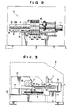
- Fig. 2 is a front elevational view of the punching device of Fig. 1;
- Fig. 3 is a side elevational view of the punching device of Fig. 1;
- Fig. 4 is a top plan view illustrating the working table of the punching device, with a portion partially cut or broken away;
- Fig. 5 is a longitudinal cross-sectional view illustrating a punching unit in more detail;
- Fig. 6 is a top plan view illustrating a circuit board to be punched;
- Fig. 7 is a perspective view illustrating a punching unit which can be used in the punching device of the present invention;
- Fig. 8 is a longitudinal cross-sectional view illustrating the punching unit of Fig. 7;
- Figs. 9 and 10 are sectional views taken along line IX-IX of Fig. 8, with Fig. 10 showing both locked (solid) and open (dashed) positions, and Fig. 9 illustrating an unlocked position of the apparatus;
- Fig. 11 is a longitudinal cross-sectional view illustrating the upper half portion of a supporting member in a position in which its lifting mechanism has been retracted; and
- Fig. 12 is a perspective view illustrating a punch and die used in the apparatus of Fig. 7.
- Referring now more specifically to the drawings, one preferred embodiment of each of the present invention herein will be described in greater detail than above. As shown in Figs. 1 - 3, a punching device A is illustrated in which the first portion of the present invention is applied. In this apparatus, a plurality of holes c, which can either be round, rectangular, or ovular, are to be punched in a plurality of desired positions in thin plate-like material, e.g. circuit board C, a flexible film or a metallic foil, as illustrated in Fig. 6.
- Punching device A comprises a plurality of punching units B₁ - B₆, as seen in Figs. 1 and 2, which are arranged in a side-by-side fashion on a working table 1. The device further comprises a plurality of moving mechanisms or
assemblies 3 for supporting one ormore holder frames 2 which retain a workpiece, e.g. a flat, thin circuit board C, and for moving the holder frames on the working table 1 along both X-axis and Y-axis directions. The device further comprises acontrol assembly 4 for controlling operation of each of the movingmechanisms 3 and each of punching units B₁ through B₆. The control unit orassembly 4 can take a variety of forms, e.g. a CPU in the form of a microprocessor. - Each of the component elements, with the exception of
control unit 4, is mounted on a base table 5, with a working table 1 fixedly positioned on base table 5. Additionally, punching units B₁ - B₆, are fixed relative to table 5. - As illustrated in Fig. 5, punching units B₁ - B₆ are provided at the upper and lower ends of a ]- shaped support rod or
element 6, in the form of punches b and dies b'. The punch and die in each punch and die pair have shapes which are complementary to each other, such that each one of punches b is lowered by liftingpiston assembly 7 in order to punch holes c having the same configuration as each of punches b in a circuit board C which is held between punches b and dies b'. Each of punching units B₁ - B₆ is positioned in an overlapped or abutting relationship with an adjacent punching unit, in a side-by-side fashion, with axial cores of punches b₁ - b₆ being installed within the units such that they are arranged in a row, along the X-axis direction, over a central portion of workpiece table 1. - Circuit board C, which is to be punched by punching units B₁ through B₆, is mounted on
holder frame 2, having a window therein, so as to cover an opening 2a inframe 2; the board is held onholder frame 2 by having its circumference held by claws orgrips 2b. -
Holder frame 2 is, in turn, clamped byclamp 8 of movingmechanism 3, and is supported horizontally on working table 1. Movingmechanism 3 comprises a lateral feeding table ormechanism 3a for feeding or movingclamp 8 along an X-axis direction and a vertical feeding table or mechanism (3b) for supporting the lateral feeding table 3a and for feeding/moving the lateral table in a generaly Y-axis direction. - Lateral feeding table 3a supports
clamp 8 alongamain body 9 of the table, and is movable along an X-axis direction in such a way that it can be slid, and so that a threadedmember 8a which is positioned on a rear surface ofclamp 8 will be threadably fitted onto anX-axis thread 10 which is rotatably supported withinmain table body 9. TheX-axis thread 10 can thereafter be rotated in both normal/forward and reverse directions by anX-axis motor 11 which is attached to one end ofmain table body 9. - Vertical feeding table 3b is provided with
slide plates base plate 5 and which are supported in such a way that they can be slid along the Y-axis direction of the apparatus. Lateral feeding table 3a is supported by bothslide plates member 14, supported withinbase plate 5, is threadably engaged within a threadedhole 13 formed at the central portion of the lateral feeding table 3a, along the Y-axis, in order to extend through thehole 13. The Y-axis threaded member is rotatably supported in both normal/forward and reverse directions by a Y-axis motor 15 which is attached to base table 5. Bothmotors control unit 4. - In this manner, holding
frame 2, which holds circuit board C, will slideclamp 8, which clampsholder frame 2, along an X-axis direction of amain table body 9, under the rotation ofX-axis motor 11. Further,main table body 9 can be moved in a Y-axis direction by Y-axis motor 15. In this fashion, the holding frame, and board C, can be moved along working table 1 in both X-axis and Y-axis directions. - Each of the above-noted punching units B₁-B₆,
X-axis motor 11, and Y-axis motor 15 of movingassembly 3 is cooperatively connected to controlunit 4. -
Control unit 4 can control the operation of each of punching units B₁-B₆, as well as starting and stoppage of each ofX-axis motor 11 and Y-axis motor 15 for movingassemblies 3, in response to data relating to the inputted punching position and hole shapes of the punches b₁-b₆. The data representing the punching positions are obtained, e.g., by amicroscope 16 which is installed in a position along an extended line of the punches b₁-b₆ which are arranged side-by-side along working table 1, which position is offset along the X-axis direction of table 1. - In order to input the punching position(s) and the shape(s) of the hole(s) to be punched, circuit board C is moved along the X-axis direction and the Y-axis direction in order to cause each of the punching positions of circuit board C to be inputted while it is aligned, in sequence, with a center of the offset
microscope 16. Simultaneously, the punched shape of the holes to be made at each of such punching positions is also selected, i.e., each of punching units B₁-B₆, which are provided with respective punches b₁-b₆ for punching out the holes, are selected to perform successive punching operations of various shapes. -
Control unit 4 will have previously stored a program for use in calculating the distance of movement which is required, along both the X and Y axes, for sequentially moving the board C so that each of the punching positions inputted at the center ofmicroscope 16, as described above, will be moved to the locations immediately below punches b₁-b₆, in order to have the punches form punched holes having desired shapes. Desired punching positions on the board are obtained sequentially, by moving the circuit board or other workpiece into a position just below the desired punches b₁-b₆, in response to the calculations made as noted above; thereafter, punching units B₁-B₆, which are provided with punches b₁-b₆, are operated, i.e., when the respective punching positions are reached immediately below desired punches b₁-b₆. -
Control unit 4 also stores data, in advance, which relates to punching positions and punched hole shapes for a plurality of different types of known circuit boards C which are to be punched. In this fashion, a program for a circuit board C to be targeted can be selected to perform punching operations in accordance with the program. - Thereafter, inputting of punching positions and the shapes of punches b₁- b₆, and the action of each of the punching units during punching operations occurs as will be described with respect to the example of circuit board C which is illustrated in Fig. 6.
- Initially, after circuit board C is accurately installed on
holder frame 2, movingmechanisms 3 are manually operated (through appropriate manual controls which are not illustrated) in order to move punched positions (a-1) of indicated round holes d below the offsetmicroscope 16, while circuit board C is being slid along working table 1 in both the X- and Y-axis directions, as illustrated in Fig. 4. Thereafter, the moving mechanisms will be finely moved while observing through the offsetmicroscope 16, with punched hole position a-1 being accurately aligned with the center ofmicroscope 16. In this condition, the punched hole position a-1 is inputted intocontrol unit 4. - After punched hole positions a-2 through a-3 are then inputted to
unit 4 in the same manner as punched hole position a-1, punching unit B₁, provided with punch b₁ for round hole d, is inputted as the punching unit for punching a plurality of round holes d. Thereafter, each of punched hole positions a-2 and a-3, for small round holes e and rectangular holes f, and punching units B₂ and B₃ for punching holes a-2 and a-3, will similarly be inputted. - In order to effect a punching operation, circuit board C, before performing a punching operation, will be installed within
holder frame 2. Thereafter, a program having the above-noted data inputted therein will be initiated bycontrol member 4. - In this fashion, for this example, moving
mechanisms 3 will be controlled bycontrol unit 4 in order to slide circuit board C along working table 1 by a desired distance in both the X- and Y-axis directions, in order to move punched hole position a-1 to a location immediately below round hole punch b₁ of punching unit B₁. Immediately thereafter,control unit 4 will operate liftingpiston 7 of punching unit B₁ and lower round hole punch b₁. As this round hole punch is lowered, punched hole position a-1 of circuit board C, which is positioned on die b'₁, will be punched out by round hole punch b₁. - Subsequently, each of the punched hole positions a-1 will be moved sequentially into a location just below the above-noted round hole punch b₁, while circuit board C is slid so as to punch a plurality of round holes d with this punch.
- Thereafter, each punched hole position a-2 is moved to a location just below small hole punch b₂ of punching unit B₂, while circuit board C is being slid in a desired direction in order to punch a first small round hole e; thereafter, punching hole positions a-3 are moved to a location just below rectangular hole punch b₃ of punching unit B₃ in order to punch a rectangular hole f, and thereafter all of the operating steps are completed.
- Subsequent to these operations on circuit board C, in situations in which another punching operation is to be effected for another circuit board, the program for such additional circuit board is subsequently inputted into the
control unit 4, and is calledup as described above. Thereafter, a punching operation is effected in accordance with the additional program. - In order to move the punching hole position of the circuit board into a position just below the desired punches, both
X-axis motor 11 and Y-axis motor 15 can be operated simultaneously to cause the desired punching hole position to be slid obliquely, i.e. theframe 8 and retained circuit boardwill move at an angle. Further, the motors can be moved linearly with respect to the punching operation or moved while the punching hole position is being separately slid along the X- and Y-axis directions. - The punching unit B, which is used in punching device A, will now be described with specific reference to Figs. 7 -12.
- Punching unit B, as shown in Fig. 8, includes a lifting mechanism g provided with a
lifting piston 7 at the upper side of a substantially ⊐ -shaped supportingmember 6; simultaneously, a punch (b), which is to be raised or lowered by liftingpiston 7, is fitted withinfitting hole 17 in the upper side section or portion of the supportingmember 6; and (female) die b′, which corresponds in shape to the extreme (lower) end of punch b, is fixed to the lower section of supportingmember 6. - Supporting
member 6 comprises a steel plate of a desired thickness which is formed into a substantially -configuration, and has a dovetail-shapedportion 18, with lifting mechanism g fitted on the dovetailed portion. The mechanism g includes a lower recess or grooved portion 29 (see Figure 12) which can be slidably mounted onmember 18. - Punch (b) is pushed through (i.e., punched) the upper surface of
support member 6 in such a way that it can be moved through theinsertion fixing hole 17 andinsertion hole 20, for insertingholder 19 for die b′, is formed at a location immediately below fixinghole 17 on the lower portion of supportingrod 6 so that the die will receive the punch. - A generally T-configured
groove 21 is formed along the lower (under) side of supportingmember 6; andgroove 21 is fitted to a fixingrail 22 having a T-shaped section which is arranged on base table 5 of punching hole device A in order to cause supportingrod 6 to be detachably fixed, in a desired position, on base table 5. In this manner,assembly 7 can be removed frommember 6 when desired. - A longitudinal hole or bore 23 is formed in
member 6 at a location just below dovetail-shapedportion 18 of supportingmember 6; and acam shaft 24 is fitted intolongitudinal hole 23. Simultaneously, a lockingpiece 26 is inserted into anopening 25 on the upper surface of the dovetailedportion 18, and is mounted on acam portion 24a ofcam shaft 24, as illustrated in Fig. 9. Further, as illustrated in Fig. 11,cam shaft 24 can be rotated by a tool (i) such that lockingpiece 26 will be pushed upwardly withcam portion 24a, and thereafter will project upwardly from opening 25 on the upper surface ofdovetail 18. This will lock the assembly g onmember 6, as shown in Fig. 10. - Lifting mechanism g, which is to be mounted along the upper side of supporting
member 6, is constructed by positioning liftingpiston 7 intomain body 27 of the lifting mechanism. A dovetail-shapedgroove 29 is formed at the bottom surface ofmain body 27, with the groove being fitted withindovetail portion 18 along the upper side of the noted supportingrod 6. In this fashion,main body 21 can be slidably moved from a desired, fixed position rearwardly, or from a rearward position to the fixed position. Whenmain body 27 of the lifting mechanism is positioned at its fixed position,cam shaft 24 will be rotated in order to force lockingpiece 26 to be pushed upwardly. In this fashion,main body 27 will be locked at the position illustrated in Fig. 10; and the cam shaft can then be rotated in an opposite direction in order to lowerlock piece 24 so as to release the lock piece, as illustrated in Fig. 9. - At a location immediately above punch b of
main body 27 of the lifting mechanism, alifting piston assembly 7 is vertically installed. This lifting piston assembly comprises anupper lifting piston 7a and alowering piston 7b with ashaft 7c, each ofpistons separate cylinders discharge holes cylinders lifting piston assembly 7. The cylinders can alternatively be hydraulically actuated in a conventional fashion. - Lifting
piston assembly 7 is provided with astop pin 30, which projects outwardly from the upper portion ofcylinder 28a, with the extreme end ofstop pin 30 abutting against adjustingscrew 31, the screw being rotatable in order to adjust the lifting position of liftingpiston 7. - In turn, an internally threaded connecting
fitting piece 32 is attached to the lower surface of descendingpiston 7b, as illustrated in Figs. 11 and 12. Connectingfitting piece 32 is formed by bending a steel plate into a substantially ⊐ -shape, with a forkedend 32a being formed at one extreme end of the fitting attachment;piece 32 is threadably attached to the lower surface of thesame piston rod 7b. - Within fixing
hole 17, which is formed directly below thelifting piston rod 7b, acylindrical bearing 33 is positioned having a desired number of injectingholes 33a located on its circumferential surface. Simultaneously, an axial punch b is fitted within bearing 33 with a desired clearance being left between the outer punch surface and the inner bearing surface. Compressed air to be supplied from a compressor pump, not shown in the drawings, is supplied intoclearance 35, within the circumferential surface inside bearing 33, throughair supply passage 34. - Compressed air which is supplied to the
clearance 35 is injected into the clearance between outer circumferential surface of punch b and the inner circumferential surface of bearing 33, through each ofinjection holes 33a, and is thereafter discharged from both ends of bearing 33. - Thereafter, punch b is supported by a film of compressed air which is generated in the clearance between the outer circumferential surface of the punch and the inner circumferential surface of bearing 33, and is supported in such a way that it can either be lifted or lowered.
- Punch b is constructed, as seen in Figs. 7 and 8, so that a push cutting blade b₂ for punching out a target hole at the extreme end of the axial punch main body b₁ will be removably fit therein; further, a silicon rubber pusher member b₃ is fitted to cover the circumference of push cutting blade b₂, and a fitting groove b₄ is formed at the circumferential surface of punch b, at the end opposite from the punching end.
- One end of a
connector plate 36 is then removably fitted to a rear (i.e., top) end of punch b, and, further, aguide shaft 37 is fitted to the other end ofconnector plate 36 in order to hold punch b and guideshaft 37 in a generally horizontally spaced condition.Guide shaft 37 is, in turn, fitted and inserted into aslide bearing 38 fitted to a side portion of fixinghole 17. In this fashion, punch b is guided byguide shaft 37, and is thereafter raised or lowered along the center of bearing 33. - In order to connect the rear end of punch b, which is fitted within bearing 33, to the lower surface of lowering
piston 7b, fitting groove b₄ at the rear end of punch b is fitted into and engaged within the forkedend 32a of connectingfitting piece 32, which is threadably engaged with loweringpiston 7b when the retracted lifting mechanism g is being slid towards its attaching position. Thereafter, connectingfitting piece 32 is rotated along its fastening direction and is fastened until the end portion of punch b is pushed against the lowest surface of descendingpiston 7b. When punch b has a shape other than a round shape, it is connected while the angular position of the punch b, in its circumferential direction, is adjusted. When punch b is connected to loweringpiston 7b,cam shaft 24 is rotated by tool (i) in order to lock lifting mechanism g in its fixed position. During replacement or maintenance of punch b, the above-noted lock is released, and connectingfitting piece 32 is loosened. Thereafter, lifting mechanism g is retracted and punch b is pulled upwardly, as shown in Fig. 11. - Die b′, corresponding to punch b, is fitted within
die installation hole 19c ofbase plate 19a ofholder 19, as illustrated in Fig. 7, in such a way that it can be either fitted or removed from the hole.Tubular portion 19b ofholder 19 is fitted intoinsertion hole 20, at the lower end of supportingrod 6, in order to fit die b′ below punch b. Thetubular portion 19b ofholder 19 is formed so as to have a diameter which is slightly smaller than the diameter of the insertion hole, and is constructed so that it can be slid in its diametrical direction. In this fashion,holder 19 can be slid upwardly into a position in which the push cutting blade b₂ of punch b is accurately fitted to die b′ when punching is effected.Holder 19 is positioned in a locked position against supportingmember 6 by a locking mechanism h which is described hereinafter. - Locking mechanism h is internally installed in a space formed at the lower side of supporting
member 6. Twoarm plates 39, 39 (of which one is shown in Fig. 8), are pivotably supported by a supportingshaft 40, with the extreme end ofarm plates engagement portion 39a; simultaneously, cam portion 41a ofcam shaft 41 is fitted to the rear ends ofarm plates cam shaft 41 are supported by the main body of supportingelement 6.Engagement member 39a is inserted into the space between stoppingthreads tubular portion 19b ofholder 19.Cam shaft 41 is rotated in order to cause theengagement portion 39a to pulltubular member 19b downwardly, andbase plate 19a is pushed against the tubular member aroundinsertion hole 20 of supportingelement 6. Consequently, the tubular member is locked against movement. - When a die b′ has a hole other than a round hole, and is attached to
holder 19, the die is aligned in a position so as to adjust its circumferential angular position; and, thereafter, it is locked. - Fig. 5 illustrates a condition in which a punching unit B, constructed as noted above, is mounted within
base plate 5. Circuit board C, which is subjected to punching action, is then installed inholder frame 2 and held on die b′; the punching position is then set at a location directly below punch b. - Thereafter, punch b is lowered, and the punching hole of circuit board C is punched out with push cutter blade b₂ of punch b. At such time, since circuit board C is pushed onto die b, by pushing member b₃, which is located at the extreme end of punch b, it will not vibrate when it is punched outwardly by push cutter blade b₂. Accordingly, a clear/clean hole can be punched out at an accurate position.
- The above-noted punching unit B facilitates attachment and removal of punches b and dies b'. Simultaneously, punching unit B can itself be attached vertically on base table 5 of punching device A and can be removed therefrom. In this fashion, replacement of each punching unit B with a new unit, or changing the position of the punching unit, can be facilitated, and maintenance thereof can be smoothly achieved.
- Setting the position and adjusting the angle of dies b' can also be easily and accurately performed.
- The punching unit B can be used in conventional types of punching devices as well as in the punching assembly of the present invention.
Claims (30)
- A punching device for punching at least one hole in a thin, substantially flat, workpiece (C), said punching device comprising:(a) a substantially horizontal work table (1) upon which a workpiece (C) to be punched is adapted to be movably positioned;(b) at least one holder frame (2) for movably holding said work piece on an upper surface of the said table (1);(c) a moving assembly (3) for moving each said holder frame (2) in both a X-axis direction and a Y-axis direction along an upper surface of said table (1);(d) a punching member for punching holes in the workpiece (C);(e) a control unit (4) for inputting data representative of desired punching locations on the said workpiece (C) and of the shape of each punch to be made, said control unit (4) comprising means for controlling the operation of said moving assembly and said punching member in response to any data which is inputted; and characterised in that(f) the punching member comprises a plurality of punching units (B1-B6), each of said punching units having a punch (b) and a die (b') of a predetermined shape wherein the punches of at least two punching units have different shapes so as to punch different shaped holes in the workpiece (C).
- A punching device in accordance with Claim 1 wherein the control unit comprises means for moving the workpiece into desired punching positions below said punching units.
- A punching device in accordance with Claim 1, wherein said control unit further comprises means for controlling movement of said assembly (3) to position said workpiece (C) at a plurality of predetermined positions which are to be punched, each punching unit (B1-B6) comprising means for punching said workpiece at each of said predetermined positions.
- A punching device in accordance with claim 1, wherein said working table (1) is substantially flat and is positioned in a horizontal fashion on a base table.
- A punching device in accordance with claim 4 wherein each of said punching units (B1-B6) comprises a generally ]-shaped supporting member (6) having an upper portion and a lower portion, with a punch (b) being positioned in the upper portion of each said supporting member and a die (b') being positioned in the lower portion of each said supporting member.
- A punching device in accordance with claim 5, wherein the punches (b) in said punching units are aligned in a substantially linear fashion.
- A punching device in accordance with claim 1, each of said frames (2) having a window (2a), wherein said workpiece (c), when positioned in said holder frame, is visible through said window.
- A punching device in accordance with claim 1, wherein each said frame (2) includes at least one clamp (8) for detachably retaining a workpiece within said frame.
- A punching device in accordance with claim 1, wherein said moving assembly (3) comprises a lateral feeding mechanism (3a) for moving each of said frames (2) in a substantially X-axis direction along said upper table surface and a longitudinal feeding mechanism (3b) for supporting said lateral feeding mechanism and for moving said lateral feeding mechanism in a substantially Y-axis direction along said upper table surface.
- A punching device in accordance with claim 9, wherein said lateral feeding table (3a) includes a threaded rotatable screw (10) which is driven by a first motor (11), said screw being positioned within a threaded aperture (8a) in a clamping member which engages said frame.
- A punching device in accordance with claim 10, wherein said longitudinal feeding mechanism comprises a threaded screw (14) which is driven by a second motor (15), and a plurality of clamps which engage an outer surface of said lateral feeding mechanism.
- A punching device in accordance with claim 11, wherein both of said motors are controlled by said control unit (4), said control unit comprising a microprocessor.
- A punching device in accordance with claim 1, further comprising a microscope (16) aligned with, and offset from, each said punching unit (B1-B6), said microscope comprising means for determining position on said workpiece which are to be punched.
- A method of punching a plurality of holes in desired positions on a workpiece (C), each of said holes having a desired shape, said method comprising:-(a) inputting data into a control unit (4), said data relating to a plurality of desired positions at which said holes are to be punched;(b) sequentially moving said workpiece (C) to said plurality of desired positions;(c) punching a hole, at each of the desired workpiece positions and characterised in that said control unit controls the operation of a plurality of adjacent punching units (B1-B6), each having a punch and a die of predetermined shape, wherein the punches of at least two punching units have different shapes so that a plurality of holes of predetermined shape are punched in the workpiece.
- A method in accordance with claim 14, further comprising determining said punching positions to be input by moving said workpiece along both X-axis and Y-axis direction of a horisontal surface (1) and causing each of said plurality of desired punching positions to be inputted into said control unit (4) when each said punching position is sequentially aligned with a viewing instrument (16).
- A method in accordance with claim 15, wherein each of said punching positions is sequentially aligned with a center of a microscope (16).
- A method in accordance with claim 14, further comprising precisely positioning said workpiece within a moveable holder frame (2).
- A method in accordance with claim 14, wherein said holes are punched by sequentially moving said workpiece to desired punching positions, and punching a shaped-hole with a shaped punch at each of said positions.
- A punching device according to Claim 1 including for each punch a lifting assembly (g), said lifting assembly including a movably positioned lifting piston (7) attached to one side of a substantially ]-shaped supporting member (6), said supporting member (6) comprising at least one attaching hole (17) with the punch detachably fitted within said attaching hole (17), said assembly (g) further comprising means (7) for lifting and lowering said punch, said punch (B1-B6) including a front end and a rear end, said supporting member (b) further comprising a die (b') corresponding to said punch, said die being detachably positioned within a lower portion of said supporting member characterised in that said punch rear end is mounted so as to be bodily separable from said lifting piston (7a) to enable replacement of the punch.
- A punching device in accordance with claim 19 wherein said support member comprises a steel plate having a predetermined thickness.
- A punching device in accordance with claim 19, further comprising a dovetail-shaped fastening member (18) positioned on an upper surface of said support member (6), said fastening member being fitted within a groove (29) on a lower surface of said lifting assembly.
- A punching device in accordance with claim 19, said supporting member further comprising a substantially longitudinal bore (23), said supporting member further comprising a cam shaft (24) fitted within said longitudinal bore and a locking element (26) movably positioned in said bore (23), said locking element (26) being moveable into a locked position in which it protrudes through an opening in said fastening member and extends into said groove.
- A punching device in accordance with claim 19, wherein said punch lifting assembly (g) includes a punch lifting piston assembly (7) which is connected to said upper surface of said support member (6) and which comprises means for raising and lowering said punch (b) within said attachment hole (17).
- A punching device in accordance with claim 23, said lifting piston assembly (7) comprising a lifting piston (7a), a lowering piston (7b), and a shaft (7c) connecting said two pistons (7a, 7b), each of said pistons being fitted into a separate cylinder (28a, 28b).
- A punching device in accordance with claim 24 further comprising means (29a, 29b), for selectively supplying compressed air to, and removing compressed from, said cylinders.
- A punching device in accordance with claim 25, wherein said attachment hole (17) has a substantially cylindrical bearing (33) fitted therein, and wherein said punch (b) is fitted within said bearing (33) such that a predetermined clearance (35) is located between said punch and said bearing.
- A punching device in accordance with claim 26, further comprising means (34) for supplying compressed air to said clearance.
- A punching device in accordance with claim 23, further comprising a connector plate (36) attached to said rear end of said punch (b), and a guide shaft (37) positioned in a bore in said supporting member (6), said guide shaft (37) having one end engaged by said connector plate (36), said connector plate 36 thereby comprising means for maintaining said punch (b) and said guide shaft (37) in a substantially horizontally spaced position.
- A punching device in accordance with claim 19, further comprising a locking mechanism (h) for maintaining said die (b') within a bore (19C) in said lower portion of said support member.
- A punching device in accordance with claim 29, wherein said locking mechanism (h) comprises two arm plates (39) pivotably supported by a support shaft (40) which detachably supports said die (b'), each of said arm plates (39) having a first end which is adapted to engage a rotatable cam shaft (41).
Applications Claiming Priority (2)
| Application Number | Priority Date | Filing Date | Title |
|---|---|---|---|
| JP102198/87 | 1987-04-24 | ||
| JP62102198A JPH08398B2 (en) | 1987-04-24 | 1987-04-24 | Punching device for thin plate and punching unit for punching device |
Publications (3)
| Publication Number | Publication Date |
|---|---|
| EP0287986A2 EP0287986A2 (en) | 1988-10-26 |
| EP0287986A3 EP0287986A3 (en) | 1989-11-15 |
| EP0287986B1 true EP0287986B1 (en) | 1994-01-12 |
Family
ID=14320963
Family Applications (1)
| Application Number | Title | Priority Date | Filing Date |
|---|---|---|---|
| EP88106132A Expired - Lifetime EP0287986B1 (en) | 1987-04-24 | 1988-04-18 | Punching device for thin plates and punching units used with punching device |
Country Status (4)
| Country | Link |
|---|---|
| US (1) | US5027683A (en) |
| EP (1) | EP0287986B1 (en) |
| JP (1) | JPH08398B2 (en) |
| DE (1) | DE3886979T2 (en) |
Families Citing this family (38)
| Publication number | Priority date | Publication date | Assignee | Title |
|---|---|---|---|---|
| JP2570372B2 (en) * | 1988-03-18 | 1997-01-08 | 富士通株式会社 | Wiring board punch |
| US4990080A (en) * | 1988-06-29 | 1991-02-05 | Ushio Co. Ltd. | Punch press for piercing green sheet with liner |
| JPH0215294U (en) * | 1988-07-06 | 1990-01-30 | ||
| JPH071278Y2 (en) * | 1988-07-28 | 1995-01-18 | ウシオ株式会社 | Punching unit for punching device |
| JPH02124295A (en) * | 1988-10-28 | 1990-05-11 | Ushio Kk | Multishaft boring device |
| JPH02180583A (en) * | 1988-12-29 | 1990-07-13 | Ushio Kk | Multiple shaft punching device |
| EP0367185B1 (en) * | 1988-10-31 | 1994-07-06 | Ushio Co. Limited | Multiple piercing apparatus and method |
| JPH0435898A (en) * | 1990-05-31 | 1992-02-06 | Ushio Kk | Hole piercing device for such work as circuit substrate and its material sheet |
| JPH0443432U (en) * | 1990-08-09 | 1992-04-13 | ||
| JPH07171794A (en) * | 1993-11-30 | 1995-07-11 | U H T Kk | Punching device |
| JP2740141B2 (en) * | 1995-09-22 | 1998-04-15 | ユーエイチティー株式会社 | Perforator |
| JP3442590B2 (en) * | 1995-11-20 | 2003-09-02 | 株式会社アマダ | Punching machine and machining method |
| US5743164A (en) * | 1996-03-01 | 1998-04-28 | Guez; Allon | Automatic reconfigurable die |
| US5771768A (en) * | 1996-03-05 | 1998-06-30 | Malmstrom; Wayne | Hole punch with quick-change die assembly |
| US6047623A (en) * | 1996-03-05 | 2000-04-11 | Performance Design, Inc. | Hole punch quick-change die assembly with pin strap and positioning system |
| US6536321B2 (en) | 1996-03-05 | 2003-03-25 | Performance Design, Inc. | Hole punch quick-change die assembly with clamp system |
| US6363826B1 (en) * | 1996-03-05 | 2002-04-02 | Performance Design, Inc. | Hole punch quick-change die assembly with pin strap and positioning system |
| FR2750912B1 (en) * | 1996-07-15 | 1998-11-06 | Automa Tech Sa | PRINTED CIRCUIT PLATE PUNCHING MACHINE |
| FR2800312B1 (en) * | 1999-10-29 | 2002-01-25 | Automa Tech Sa | PUNCHING MACHINE FOR PANELS |
| EP1205268B1 (en) * | 2000-11-08 | 2004-07-28 | Trumpf GmbH & Co | Machine tool with drive device |
| US6769339B2 (en) | 2001-06-25 | 2004-08-03 | General Binding Corporation | Die set pin retainer |
| JP4339548B2 (en) * | 2002-03-15 | 2009-10-07 | 株式会社堀鐵工所 | Punching machine |
| US7343770B2 (en) * | 2002-08-16 | 2008-03-18 | Nanoprecision Products, Inc. | Stamping system for manufacturing high tolerance parts |
| US7418309B2 (en) | 2005-09-22 | 2008-08-26 | The Bradbury Company, Inc. | Methods and systems for optimizing punch instructions in a material forming press system |
| US8096162B2 (en) * | 2006-02-15 | 2012-01-17 | Heiko Schmidt | Hydraulic processing pincers |
| CN101274346B (en) * | 2007-03-28 | 2010-12-29 | 鸿富锦精密工业(深圳)有限公司 | Method for producing metallic stamping pieces |
| US9364048B2 (en) | 2010-05-10 | 2016-06-14 | Nike, Inc. | Method of using efficient die cutting pattern for footwear manufacture |
| DE102011075035A1 (en) * | 2011-04-29 | 2012-10-31 | Hamilton Bonaduz Ag | Punching device with modular punching means |
| DE202014001697U1 (en) * | 2014-02-25 | 2015-05-27 | Engelbreit + Sohn Gmbh Cnc-Zerspannung | Assembly plant for automatic joining of components |
| CN107571325B (en) * | 2017-10-09 | 2019-03-22 | 江苏大浪电气集团有限公司 | A kind of lamp housing tapping equipment for stablizing aperture |
| CN109089380A (en) * | 2018-09-27 | 2018-12-25 | 房利鹏 | A kind of cross cable-through hole shaping equipment of FPC plate |
| CN109352736A (en) * | 2018-11-26 | 2019-02-19 | 盛州医药包装材料科技(中国)有限公司 | A kind of blanking units for rubber plug |
| DE202019101952U1 (en) * | 2019-04-04 | 2019-05-03 | Iwm Automation Gmbh | punching machine |
| CN112140220B (en) * | 2020-09-15 | 2024-08-27 | 长虹美菱股份有限公司 | Punching equipment for inclined plane of refrigerator liner |
| CN112792904B (en) * | 2020-12-30 | 2024-06-07 | 天津诺瑞信精密电子有限公司 | Automobile interior trim part punching die with punching position adjustable |
| CN113001661B (en) * | 2021-02-03 | 2022-12-16 | 江苏舜天股份有限公司 | Clothes punching mechanism and method for preventing clothes from being dragged by polishing head |
| CN113618832A (en) * | 2021-08-18 | 2021-11-09 | 孙兴兴 | Shell processing equipment is used in VR glasses production |
| CN114390785B (en) * | 2021-12-09 | 2023-06-23 | 珠海市代工机械设备有限公司 | Full-automatic special-shaped punching machine for flexible circuit board |
Family Cites Families (8)
| Publication number | Priority date | Publication date | Assignee | Title |
|---|---|---|---|---|
| US3368439A (en) * | 1965-05-05 | 1968-02-13 | Electrographic Corp | Apparatus for preparing multipage printing |
| US3717059A (en) * | 1971-03-18 | 1973-02-20 | Amada Ltd | Ironworker |
| US3768351A (en) * | 1972-05-08 | 1973-10-30 | Gte Automatic Electric Lab Inc | Method and apparatus for forming holes in a material |
| DE2738344C2 (en) * | 1977-08-25 | 1986-01-16 | Trumpf Maschinen AG, Zug | Punching machine |
| JPS5855135A (en) * | 1981-09-29 | 1983-04-01 | Amada Co Ltd | Punch press |
| JPS60228099A (en) * | 1984-04-20 | 1985-11-13 | 株式会社日立製作所 | Punching working method |
| JPH0661668B2 (en) * | 1985-02-04 | 1994-08-17 | 株式会社アマダ | Tool management system for machine tools |
| US4685613A (en) * | 1986-09-16 | 1987-08-11 | Frank Schambre | Reciprocable tool mounting module |
-
1987
- 1987-04-24 JP JP62102198A patent/JPH08398B2/en not_active Expired - Fee Related
-
1988
- 1988-04-05 US US07/177,930 patent/US5027683A/en not_active Expired - Lifetime
- 1988-04-18 EP EP88106132A patent/EP0287986B1/en not_active Expired - Lifetime
- 1988-04-18 DE DE88106132T patent/DE3886979T2/en not_active Expired - Fee Related
Also Published As
| Publication number | Publication date |
|---|---|
| JPS63267195A (en) | 1988-11-04 |
| DE3886979D1 (en) | 1994-02-24 |
| EP0287986A3 (en) | 1989-11-15 |
| EP0287986A2 (en) | 1988-10-26 |
| DE3886979T2 (en) | 1994-04-28 |
| US5027683A (en) | 1991-07-02 |
| JPH08398B2 (en) | 1996-01-10 |
Similar Documents
| Publication | Publication Date | Title |
|---|---|---|
| EP0287986B1 (en) | Punching device for thin plates and punching units used with punching device | |
| DE102014209811B4 (en) | Device for mutual separation of two workpiece parts of a plate-like workpiece | |
| DE3852634T2 (en) | Riveting process and device. | |
| EP1798019B1 (en) | Apparatus for performing punching, milling, welding or gluing processing steps on large surfaced, three dimensional plastic workpieces | |
| DE3438584A1 (en) | DEVICE FOR RIVETING TWO OR MORE SHEETS OF A SHEET STRUCTURE | |
| DE60302036T2 (en) | tooling | |
| US4304041A (en) | Automatic tool changer for forging machines | |
| DE69002143T2 (en) | Punching machine. | |
| EP0983810A2 (en) | Automatic tool changing machine | |
| US4629384A (en) | Transfer and locator of workpieces for a gang machine | |
| EP2254730B1 (en) | Tool magazine for a machine tool with an expansion device at a loading station | |
| US6220137B1 (en) | Press apparatus | |
| WO2016180401A1 (en) | Method and machining device for clamping and machining an electrical enclosure component | |
| EP1000734A2 (en) | Press apparatus | |
| DE10355057A1 (en) | Internal broaching machine and internal broaching tool | |
| JPH07185692A (en) | Press device | |
| JP2003136144A (en) | Bending apparatus | |
| DE3226605A1 (en) | CLAMPING HEAD FOR MACHINE TOOLS | |
| EP2512757B1 (en) | Processing station and method for the operation thereof | |
| EP0582357A1 (en) | Quick changeover die clamping apparatus for platen die-cutting machines | |
| KR920010772B1 (en) | Punching device for thin plates and punching units used with punching device | |
| EP0422284B1 (en) | Drill fracture controlling method for a circuit board drilling machine | |
| DE102017218439A1 (en) | Wire EDM | |
| CN220445758U (en) | Cutting device for milling cutter processing | |
| JP3270941B2 (en) | Label punching machine with blade-type automatic holding mechanism |
Legal Events
| Date | Code | Title | Description |
|---|---|---|---|
| PUAI | Public reference made under article 153(3) epc to a published international application that has entered the european phase |
Free format text: ORIGINAL CODE: 0009012 |
|
| AK | Designated contracting states |
Kind code of ref document: A2 Designated state(s): DE FR GB IT SE |
|
| PUAL | Search report despatched |
Free format text: ORIGINAL CODE: 0009013 |
|
| AK | Designated contracting states |
Kind code of ref document: A3 Designated state(s): DE FR GB IT SE |
|
| 17P | Request for examination filed |
Effective date: 19900113 |
|
| 17Q | First examination report despatched |
Effective date: 19910219 |
|
| GRAA | (expected) grant |
Free format text: ORIGINAL CODE: 0009210 |
|
| ITF | It: translation for a ep patent filed | ||
| AK | Designated contracting states |
Kind code of ref document: B1 Designated state(s): DE FR GB IT SE |
|
| REF | Corresponds to: |
Ref document number: 3886979 Country of ref document: DE Date of ref document: 19940224 |
|
| PLBE | No opposition filed within time limit |
Free format text: ORIGINAL CODE: 0009261 |
|
| STAA | Information on the status of an ep patent application or granted ep patent |
Free format text: STATUS: NO OPPOSITION FILED WITHIN TIME LIMIT |
|
| 26N | No opposition filed | ||
| EAL | Se: european patent in force in sweden |
Ref document number: 88106132.9 |
|
| PGFP | Annual fee paid to national office [announced via postgrant information from national office to epo] |
Ref country code: SE Payment date: 19960327 Year of fee payment: 9 |
|
| PG25 | Lapsed in a contracting state [announced via postgrant information from national office to epo] |
Ref country code: SE Effective date: 19970419 |
|
| EUG | Se: european patent has lapsed |
Ref document number: 88106132.9 |
|
| REG | Reference to a national code |
Ref country code: GB Ref legal event code: IF02 |
|
| PGFP | Annual fee paid to national office [announced via postgrant information from national office to epo] |
Ref country code: GB Payment date: 20040220 Year of fee payment: 17 |
|
| PGFP | Annual fee paid to national office [announced via postgrant information from national office to epo] |
Ref country code: FR Payment date: 20040423 Year of fee payment: 17 |
|
| PG25 | Lapsed in a contracting state [announced via postgrant information from national office to epo] |
Ref country code: GB Free format text: LAPSE BECAUSE OF NON-PAYMENT OF DUE FEES Effective date: 20050418 |
|
| PGFP | Annual fee paid to national office [announced via postgrant information from national office to epo] |
Ref country code: DE Payment date: 20050624 Year of fee payment: 18 |
|
| GBPC | Gb: european patent ceased through non-payment of renewal fee |
Effective date: 20050418 |
|
| PG25 | Lapsed in a contracting state [announced via postgrant information from national office to epo] |
Ref country code: FR Free format text: LAPSE BECAUSE OF NON-PAYMENT OF DUE FEES Effective date: 20051230 |
|
| REG | Reference to a national code |
Ref country code: FR Ref legal event code: ST Effective date: 20051230 |
|
| PGFP | Annual fee paid to national office [announced via postgrant information from national office to epo] |
Ref country code: IT Payment date: 20060430 Year of fee payment: 19 |
|
| PG25 | Lapsed in a contracting state [announced via postgrant information from national office to epo] |
Ref country code: DE Free format text: LAPSE BECAUSE OF NON-PAYMENT OF DUE FEES Effective date: 20061101 |
|
| PG25 | Lapsed in a contracting state [announced via postgrant information from national office to epo] |
Ref country code: IT Free format text: LAPSE BECAUSE OF NON-PAYMENT OF DUE FEES Effective date: 20070418 |