EP0287404A2 - Pressure developer - Google Patents
Pressure developer Download PDFInfo
- Publication number
- EP0287404A2 EP0287404A2 EP88303490A EP88303490A EP0287404A2 EP 0287404 A2 EP0287404 A2 EP 0287404A2 EP 88303490 A EP88303490 A EP 88303490A EP 88303490 A EP88303490 A EP 88303490A EP 0287404 A2 EP0287404 A2 EP 0287404A2
- Authority
- EP
- European Patent Office
- Prior art keywords
- roll
- pressure
- rolls
- loading
- nip
- Prior art date
- Legal status (The legal status is an assumption and is not a legal conclusion. Google has not performed a legal analysis and makes no representation as to the accuracy of the status listed.)
- Withdrawn
Links
Images

Classifications
-
- G—PHYSICS
- G03—PHOTOGRAPHY; CINEMATOGRAPHY; ANALOGOUS TECHNIQUES USING WAVES OTHER THAN OPTICAL WAVES; ELECTROGRAPHY; HOLOGRAPHY
- G03G—ELECTROGRAPHY; ELECTROPHOTOGRAPHY; MAGNETOGRAPHY
- G03G15/00—Apparatus for electrographic processes using a charge pattern
-
- G—PHYSICS
- G03—PHOTOGRAPHY; CINEMATOGRAPHY; ANALOGOUS TECHNIQUES USING WAVES OTHER THAN OPTICAL WAVES; ELECTROGRAPHY; HOLOGRAPHY
- G03F—PHOTOMECHANICAL PRODUCTION OF TEXTURED OR PATTERNED SURFACES, e.g. FOR PRINTING, FOR PROCESSING OF SEMICONDUCTOR DEVICES; MATERIALS THEREFOR; ORIGINALS THEREFOR; APPARATUS SPECIALLY ADAPTED THEREFOR
- G03F7/00—Photomechanical, e.g. photolithographic, production of textured or patterned surfaces, e.g. printing surfaces; Materials therefor, e.g. comprising photoresists; Apparatus specially adapted therefor
- G03F7/002—Photomechanical, e.g. photolithographic, production of textured or patterned surfaces, e.g. printing surfaces; Materials therefor, e.g. comprising photoresists; Apparatus specially adapted therefor using materials containing microcapsules; Preparing or processing such materials, e.g. by pressure; Devices or apparatus specially designed therefor
- G03F7/0022—Devices or apparatus
- G03F7/0027—Devices or apparatus characterised by pressure means
-
- G—PHYSICS
- G03—PHOTOGRAPHY; CINEMATOGRAPHY; ANALOGOUS TECHNIQUES USING WAVES OTHER THAN OPTICAL WAVES; ELECTROGRAPHY; HOLOGRAPHY
- G03B—APPARATUS OR ARRANGEMENTS FOR TAKING PHOTOGRAPHS OR FOR PROJECTING OR VIEWING THEM; APPARATUS OR ARRANGEMENTS EMPLOYING ANALOGOUS TECHNIQUES USING WAVES OTHER THAN OPTICAL WAVES; ACCESSORIES THEREFOR
- G03B2227/00—Photographic printing apparatus
- G03B2227/32—Projection printing apparatus, e.g. enlarging apparatus, copying camera
- G03B2227/325—Microcapsule copiers
Definitions
- the invention relates generally to pressure developers.
- the invention has been particularly devised for use in an imaging system utilizing imaging sheets having a surface coating of rupturable photosensitive microcapsules and, more particularly, in apparatus for rupturing the microcapsules on such imaging sheets.
- the colour former image-wise reacts with the developer material and produces a colour image.
- the microcapsules are typically ruptured by passing image-wise exposed imaging sheets through the nip between a pair of parallel calender rolls.
- the media may exist in either single-sheet or two-sheet versions.
- the microcapsules and developer composition are both coated on to a single substrate layer.
- the micro-capsules are carried on a first substrate layer referred to as a donor sheet.
- the developer composition is coated on to a second, separate substrate layer referred to as a receiver sheet.
- the donor sheet is subjected to the actinic radiation, and the exposed microcapusle layer is then brought into contact with the developer layer of the receiver sheet.
- the two sheets are then developed by pressure, with the finished image being formed in the receiver sheet.
- Typical pressure roll devices for fixing fusible toner images can apply approximately 1000 lbs/in2 (7 ⁇ 106N/m2).
- pressures of 6000 to 8000 lbs/in2 (4.1 ⁇ 107 to 5.5 ⁇ 107 N /m2) are required.
- the bending of the second roll can be adjusted by the cross angle of the back-up roll relative to the second roll such that both the second roll and the back-up roll may have a smaller diameter than the first roll. Even in this case, however, the skew angle between the nip rolls must still be relatively small to avoid wrinkling of the sheets.
- a pressure developer in which an image on sheet or web material is developed by passing the material between the nip of first and second cylindrical pressure rolls to exert a high localized pressure on the material across a working zone corresponding to the width of the material, characterised by: one of the pressure rolls being hollow and having a support shaft extending through the roll and joined at an axial central region of the roll, and extending axially outwardly from each side of the central region in non-contacting relation to the roll, a loading force applied to the ends of the shaft for pressure-loading said rolls together along the nip, and one of the rolls formed with an internal relief outwardly of the working zone for substantially relieving pressure between the rolls at the regions thereof axially outwardly of the zone.
- embodiments of developer constructed according to the present invention may be used in apparatus for forming images on imaging sheet material, such as sheet material, in which microcapsules contain a photosensitive composition which undergo a change in viscosity upon exposure to actinic radiation, a latent image on the sheet material being developed by passing the sheet material between the nip of the pair of cylindrical pressure rollers of the developer which exert a high localized pressure along the nip on the sheet material.
- Our developers are particularly adapted for use in apparatus in which the pressure between the nip is controlled throughout a working zone corresponding generally to the width of the web or sheet to be passed therethrough, and are particularly adapted to provide for reduced loading at axial locations outside of the working zone.
- a pair of pressure rolls are employed, which may be considered as first and second pressure rolls, and one of these pressure rolls, such as the first pressure roll, is hollow in that it is formed as an annular shell.
- This pressure roll incorporates or includes a loading shaft which extends axially through the roll. The shaft is joined to the hollow shell at a central region only, and clears the inside of the shell at all other regions. The remote ends of the loading shaft are for pressure loading.
- the second roll which may be approximately the same diameter as that of the first roll, may be conventionally formed of solid material and likewise provided with journalled ends which are mounted in parallel relation to the axis of the first roll.
- the total width of the pressure rolls at the region of contact therebetween defines a nip which is somewhat wider than the sheet material. It is desirable to relieve the pressure loading at regions axially outside of a working zone, corresponding to the width of the sheet material. Unloading is accomplished by forming an inside relief, corresponding to the regions to be unloaded, in one or the other of the pairs of pressure rolls.
- journalled ends of the loading shaft undergo deflection under conditions of loading, it is desirable to journal these ends on non-aligning bearings to permit the bearing blocks to twist as the axis is deflected.
- the bearing blocks are mounted on radius arms which are mounted to the support frame through non-load carrying self-aligning bearings.
- the trunion bearings for the loading shaft are not required to accommodate bending or deflecting movements of the shaft during loading and during operation, and the self-aligning bearings are not required to carry the pressure loads.
- the moment of inertia of the centre-loaded roll may be varied by suitably tapering, stepping or contouring the internal portion of this roll outwardly of the central support region, so that a near uniform curve and uniform nip pressures are obtained, considering the two rolls together.
- the curvature in the nip provides a camber which may be advantageously employed, by causing the web or sheet material to follow a path which partially wraps about the first roll, so that a slight spreading tends to occur in the web or sheet material. This provides stability for the sheet material, and avoids wrinkling.
- Figs. 1 and 4 illustrate a two-roll pressure type developer which includes a first roll 10 and a second roll 12 mounted in parallel to each other, and receiving sheet material therebetween.
- the sheet material may consist of a single sheet, but preferably consists of a donor sheet 15 and a receiver sheet 16 made in accordance with the teachings of U. S. Patent No. 4,399,209 issued August 16, 1983.
- images are form by exposing a coated composition containing a chromogenic material and the encapsulated photosensitive composition to actinic radiation, and thereafter rupturing the capsules in the presence of a developer carried on the receiver sheet.
- the capsules are ruptured by the application of a high uniform pressure in the nip between a pair of rolls, as more fully explained in the co-pending European Patent Application No. 88300866.6.
- the pressure developing rolls 10 and 12 are mounted for rotation in a frame or housing illustrated generally at 20 in Figs. 4 and 5.
- the housing structure may, advantageously, be provided with a top 22, a bottom 24, and a pair of spaced-apart side frame members 25 and 26.
- the housing 20 includes a central opening 28 there-through for passage of the sheets.
- the roll pair includes the first roll 10 which is hollow, or formed like a shell, providing a cylindrically true outer surface 30, and having an axially central part defining a loading region 32.
- a loading shaft 35 extends axially through the roll 10.
- the loading shaft 35 is a support shaft, and is joined to the roll 10 exclusively at the central loading region 32 thereof, and extends axially of the shell in non-contacting relation from the region 32.
- the shaft 35 is permanently attached to the surrounding shell portion of the roll 10 at the central region 32, and it is important that this attachment does not permit the roll to walk or creep with respect to the loading shaft during loading and flexing.
- the shaft 35 and roll 10 may be connected by copper brazing.
- the remote ends of the loading shaft 35 extend beyond the roll and define bearing surfaces 38 which receive non-aligning, thrust transmitting low-friction bearings, such as roller bearings 40(Fig. 2).
- the second roll 12 which may be solid, as shown, is rotatably mounted in the housing 20 in nip-defining relation to the roll 10. It will be seen that the roll pairs are somewhat wider than the sheet or web material to be applied thereto.
- the span at 42 represents the working zone of the rolls which, for example, may be 81 ⁇ 2 ⁇ (21.59 cm), thereby leaving small non-working regions 43 at the axially remote ends of each of the pressure rolls.
- the interior surface of the roll 10 is partially tapered, leading first from a relatively straight section 45, including an intermediate tapered section 46 and an end relief section 48.
- the taper provides for the controlled deflection of the shell portion of the roll 10, when loaded by the application of a downward force, in the direction of the arrows 50, on the bearings 40 at the ends of the roll, as illustrated in Fig. 2.
- the taper or contouring of the internal surface of the roll 10 provides for control of the moment of inertia, such that an approximately uniform pressure distribution may be defined along the nip between the roll pairs throughout the working zone 42.
- the matching of the rolls 10 and 12 is effected by considering the basic theory of beam bending, the deflections caused by shear stresses, the changes in cross-section at axial nodal positions, and the local effects consisting of deflections of the thin-walled portion of the roll 12. It has been found helpful to utilize the finite elements analysis method in calculating the expected deflections.
- the rolls 10 and 12 are cylindrical, and are mounted in the house 20 parallel to each other.
- the roll 10 is mounted for rotation in bearings 40 which, in turn, are carried in journal blocks 52, as best shown in the sectional view of Fig. 7.
- the extended ends of the roll 12 are mounted on self-aligning bearings 55, in relatively fixed journal blocks 56.
- the one end of the roll 12 is formed with a shaft extension 57 by means of which connection may be made to a drive motor 58 diagrammatically illustrated in Fig. 4.
- the roll 10 is loaded by loading on the journals 52, which transmit a loading force through the bearings 40 to the remote ends of the loading shaft 35 of the roll 10.
- loading springs 80 are positioned within spring housing portions 2 of the housing 20 and bear against a thrust collar 3.
- the force of the spring 80 is transmitted by the collar to a threaded pressure rod 85, the lower end of which is in pressure engagement with a hardened upper surface 86 of the bearing block 85.
- the upper end of the rod 85 extends above the spring housing portion 82 nd is adjustable on a nut 87 for varying the effective length of the rod 85. While the mounting and loading arrangement is shown for one end of the roll 10, it is understood that a substantially identical arrangement is provided for the other end of the roll.
- the rolls of the forming apparatus should have a high hardness. While mild steel may be satisfactory for some applications, the rolls must be protected against damage in the event of paper jams, where double or quadruple fold-overs and the like, can very substantially increase the localized loading of the rolls.
- the rolls may be loaded in the region of 500 pli (89 Kg/cm) which, in typical 9" (22.86cm) rolls as illustrated, loaded over 8.5 inches (21.59 cm) requires a load of 2,125 pounds (964 Kg), applied by the spring 30 at the journal ends.
- the rolls 10 and 12 may have a nominal length of 9.0", (22.86 cm) and a working zone length of 8.5" (21.59 cm), with the first roll 10 having a nominal diameter of 1.98" (5.0292 cm), and the second roll 12 having a nominal diameter of 2.39" (6.0706cm).
- the loading shaft 35 is of substantially uniform diameter throughout its length, with a diameter of 1.30" (3.302 cm).
- the central loading region may extend axially for 1.6" (4.064 cm), while the relatively cylindrical or straight sections 45 of the relief each have an axial length of 0.616" (1.56464cm).
- the intermediate tapered portions 46 each have a length of 2.351" (5.97154cm) and a taper of 0.1049" (0.265446cm) to 1.0" (2.54 cm).
- the second relief 48 is an axial length of 0.733" (1.86182 cm) and a taper of 0.3306" (0.839724 cm) to 1.0" (2.54 cm). While a single intermediate tapered portion is shown, the result may be achieved in different ways, including the formation in the inside surfaces of a stepped pattern, in which the wall thicknesses are varied in stepped increments.
- the rolls may thus be case hardened to a depth of at least 0.049" (1.25 mm), and hard chromium plating applied to the exposed outer surfaces, to a thickness of at least 0.002" (0.050 mm) for protection against rust.
- a camber will be formed in the rolls, as shown by the broken line 94, and the nip therebetween will not be in a straight line, but rather will be curved.
- a positive camber is formed in roll 10 and a negative camber formed in roll 12. It is thus preferred that the sheet material at least partially wrap the hollow roll 10 so that the sheet material will be transversely stretched slightly by the cambers as it enters and leaves the nip, thereby avoiding tendencies to wrinkle.
- the sheet feed mechanism as disclosed in copending European Patent Application 88300866.6 may be used.
- Figs. 3 and 7 represent a slightly modified embodiment, in which like parts are illustrated by like reference numerals with the addition of the letter a .
- the hollow roll 10a cooperates with the bottom roll 12a.
- the relief as previously defined by the second taper 48 is eliminated, and an internal axial annular relief 95 is formed at the opposite ends of the roll 12 and extends axially inwardly an amount corresponding approximately to the axial extent of the previous taper 48.
- the annular relief defined at 95 in Fig. 3 serves the same function as previously described in connection with the annular relief defined by the taper 48 to relive the pressure at the terminal end or regions of the rolls.
- a particular advantage of the two-roll system described herein is that the loading across the nip will remain substantially uniform over a wide range of total loading forces, and is thus relatively unaffected by variations in the thicknesses of the sheet material as far as uniformity is concerned. Further, truly cylindrical rolls may be used, thereby eliminating the need for crowning and/or skewing, as in prior arrangements.
Abstract
Description
- The invention relates generally to pressure developers.
- The invention has been particularly devised for use in an imaging system utilizing imaging sheets having a surface coating of rupturable photosensitive microcapsules and, more particularly, in apparatus for rupturing the microcapsules on such imaging sheets.
- Our U. S. Patents Nos. 4,440,846 and 4,399,209, the disclosure of each of which is to be regarded as incorporated herein by reference, describe an imaging system wherein a photosensitive layer, comprising micrcocapsules containing a photosensitive composition in the internal phase, is image-wise exposed to actinic radiation and subjected to a uniform rupturing force whereupon the microcapsules rupture and image-wise release the internal phase. The imaging system is particularly advantageous because it is a totally dry system and does not rely upon the application of wet developing processing solutions to produce the image. An image-forming chromogenic material, such as a substantially colourless colour former, is typically associated with the microcapsules. When the microcapsules rupture, the colour former image-wise reacts with the developer material and produces a colour image. In the embodiments described in the referenced patents, the microcapsules are typically ruptured by passing image-wise exposed imaging sheets through the nip between a pair of parallel calender rolls.
- The media may exist in either single-sheet or two-sheet versions. In the former case, the microcapsules and developer composition are both coated on to a single substrate layer. In the latter case, the micro-capsules are carried on a first substrate layer referred to as a donor sheet. The developer composition is coated on to a second, separate substrate layer referred to as a receiver sheet. The donor sheet is subjected to the actinic radiation, and the exposed microcapusle layer is then brought into contact with the developer layer of the receiver sheet. The two sheets are then developed by pressure, with the finished image being formed in the receiver sheet.
- While heavy pressure is not required to rupture the microcapsules, high pressure and large calender rolls are normally used to develop the imaging sheets. To normalize surface irregularities in the imaging sheets, substantial compression of the paper must be achieved. Thus, the use of large diameter rolls has been considered necessary to achieve a uniform distribution of the rupturing force across the surface of the imaging sheets. Otherwise, if the rupturing force is not uniformly distributed, the imaging sheets develop unevenly and the tonal characteristics of the resulting images are degraded.
- Typical pressure roll devices for fixing fusible toner images can apply approximately 1000 lbs/in² (7 × 10⁶N/m²). For the microencapsulated media, pressures of 6000 to 8000 lbs/in² (4.1 × 10⁷ to 5.5 × 10⁷ N /m²) are required.
- In pressure fixation apparatus for fixing a dry pressure fusible toner image onto a sheet of paper, it is known to use a pair of pinch rolls biased toward each other and disposed such that the axis of one roll extends at an angle relative to the axis of the other. This skewed arrangement tends to minimize irregularities of the nip between the rolls even when a paper sheet passes therebetween. However, when the skew angle is too large, creases or wrinkles are formed in the paper sheet. In order to avoid such wrinkles in the sheet, the skew angle is kept quite small. With a small skew angle, however, the rolls again must have large diameters to ensure uniform pressure along the nip due to the bending of the rolls. In addition to the added weight of the larger rolls, the loading pressure must also be increased. Hence, larger pressure mechanisms, higher compression resistant bearings, housing and so forth lead to an increased cost for the apparatus.
- To overcome these difficulties in the art of fixing fusible toner images, three roll systems have been used. Such a system is shown in U. S. Patent No. 4,343,234. In one three roll system, the two upper rolls form a pair of pinch rolls which are disposed parallel and horizontal with a slight skew angle therebetween. A third back-up roll is disposed in a crossing contact relation to the second roll. The back-up roll is biased resiliently upwards toward the second roll of the pair of pinch rolls by a pressure mechanism such that the second roll is butted against the first roll under pressure to form a nip along their contacting line through which paper sheets pass. The bending of the second roll can be adjusted by the cross angle of the back-up roll relative to the second roll such that both the second roll and the back-up roll may have a smaller diameter than the first roll. Even in this case, however, the skew angle between the nip rolls must still be relatively small to avoid wrinkling of the sheets.
- A particular inherent disadvantage of such prior art fixing or developing systems resides in the fact that the pressure across the nip is uniform only at one design pressure, and variations in the thickness of the material passing through the nip or variations in the pressure applied to the nip, causes a departure from a condition of linearity across the nip.
- Improved pressure development apparatus for imaging sheets employing photosensitive microcapsules, as described above, are disclosed in our European Patent Application No. 88300866.6 (Publication No. ), the disclosure of which is to be regarded as incorporated herein by reference. In the co-pending application, the problems introduced by skew angles at the nip or by differential roll speeds at the nip caused by crowned rolls are eliminated by the employment of separate crown rolls which coact with the pressure rolls. This allows the pressure rolls to be cylindrical and free of skew angle and free of differential surface speeds at the nip. Also, improved sheet feed arrangements are disclosed by which the sheet material may advantageously be applied to the pressure rolls in such a manner as to reduce the tendency for wrinkling of the imaging or donor sheets.
- In spite of the improvements which have been made to high pressure roll development apparatus, there exists a need for apparatus which is lighter in weight, which is capable of providing a substantially uniform nip pressure throughout a design width of the roll over varying thicknesses of sheet material and over carrying overall loadings on the rolls, and to provide a roll-type pressure developer which is inherently capable of applying a uniform pressure across a nip, over long periods of time, with a minimum of maintenance requirements.
- According to the present invention, there is provided a pressure developer in which an image on sheet or web material is developed by passing the material between the nip of first and second cylindrical pressure rolls to exert a high localized pressure on the material across a working zone corresponding to the width of the material, characterised by:
one of the pressure rolls being hollow and having a support shaft extending through the roll and joined at an axial central region of the roll, and extending axially outwardly from each side of the central region in non-contacting relation to the roll,
a loading force applied to the ends of the shaft for pressure-loading said rolls together along the nip,
and one of the rolls formed with an internal relief outwardly of the working zone for substantially relieving pressure between the rolls at the regions thereof axially outwardly of the zone. - As we shall explain, embodiments of developer constructed according to the present invention may be used in apparatus for forming images on imaging sheet material, such as sheet material, in which microcapsules contain a photosensitive composition which undergo a change in viscosity upon exposure to actinic radiation, a latent image on the sheet material being developed by passing the sheet material between the nip of the pair of cylindrical pressure rollers of the developer which exert a high localized pressure along the nip on the sheet material. Our developers are particularly adapted for use in apparatus in which the pressure between the nip is controlled throughout a working zone corresponding generally to the width of the web or sheet to be passed therethrough, and are particularly adapted to provide for reduced loading at axial locations outside of the working zone.
- In the embodiments described in detail hereinbelow, a pair of pressure rolls are employed, which may be considered as first and second pressure rolls, and one of these pressure rolls, such as the first pressure roll, is hollow in that it is formed as an annular shell. This pressure roll incorporates or includes a loading shaft which extends axially through the roll. The shaft is joined to the hollow shell at a central region only, and clears the inside of the shell at all other regions. The remote ends of the loading shaft are for pressure loading.
- The second roll, which may be approximately the same diameter as that of the first roll, may be conventionally formed of solid material and likewise provided with journalled ends which are mounted in parallel relation to the axis of the first roll. The total width of the pressure rolls at the region of contact therebetween defines a nip which is somewhat wider than the sheet material. It is desirable to relieve the pressure loading at regions axially outside of a working zone, corresponding to the width of the sheet material. Unloading is accomplished by forming an inside relief, corresponding to the regions to be unloaded, in one or the other of the pairs of pressure rolls.
- Since the journalled ends of the loading shaft undergo deflection under conditions of loading, it is desirable to journal these ends on non-aligning bearings to permit the bearing blocks to twist as the axis is deflected. The bearing blocks are mounted on radius arms which are mounted to the support frame through non-load carrying self-aligning bearings. The trunion bearings for the loading shaft are not required to accommodate bending or deflecting movements of the shaft during loading and during operation, and the self-aligning bearings are not required to carry the pressure loads.
- The moment of inertia of the centre-loaded roll, may be varied by suitably tapering, stepping or contouring the internal portion of this roll outwardly of the central support region, so that a near uniform curve and uniform nip pressures are obtained, considering the two rolls together. The curvature in the nip provides a camber which may be advantageously employed, by causing the web or sheet material to follow a path which partially wraps about the first roll, so that a slight spreading tends to occur in the web or sheet material. This provides stability for the sheet material, and avoids wrinkling.
- In order that the invention may be more readily understood, reference will now be made to the accompanying drawings, in which:
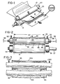
- Fig. 1 is a perspective view showing a pair of rolls constructed according to this invention with sheet material applied therebetween;
- Fig. 2 is an elevated view of the roll pairs showing the first roll in section;
- Fig. 3 is a view similar to Fig. 2, showing a slightly modified embodiment.
- Fig. 4 is a perspective view of a two-roll pressure developer made according to this invention;
- Fig. 5 is an enlarged partially broken away end view of the apparatus of Fig. 4, showing the roll mounting arm and spring loading arrangement;
- Fig. 6 is a fragmentary sectional view showing the mounting of the support arm to the frame, taken generally along the
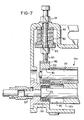
line 6--6 of Fig. 5; and - Fig. 7 is an enlarged fragmentary transverse sectional view through the pressure developer showing the preferring arrangement for mounting and driving the pressure rolls and for applying a loading force thereto.
- Figs. 1 and 4 illustrate a two-roll pressure type developer which includes a
first roll 10 and asecond roll 12 mounted in parallel to each other, and receiving sheet material therebetween. As illustrated in Figs. 1 and 4, the sheet material may consist of a single sheet, but preferably consists of adonor sheet 15 and areceiver sheet 16 made in accordance with the teachings of U. S. Patent No. 4,399,209 issued August 16, 1983. In accordance with the teachings of that patent, images are form by exposing a coated composition containing a chromogenic material and the encapsulated photosensitive composition to actinic radiation, and thereafter rupturing the capsules in the presence of a developer carried on the receiver sheet. The capsules are ruptured by the application of a high uniform pressure in the nip between a pair of rolls, as more fully explained in the co-pending European Patent Application No. 88300866.6. - Due to the high linear unit forces involved, it is important that the roll-type developer operate without differential slippage at the nip which could tend to cause the web to wrinkle. It is also important that the pressure is developed uniformly throughout a working zone of the nip, and that the pressure is relieved at regions axially outwardly of the working zone.
- The
pressure developing rolls side frame members housing 20 includes acentral opening 28 there-through for passage of the sheets. - As shown in Fig. 2, the roll pair includes the
first roll 10 which is hollow, or formed like a shell, providing a cylindrically trueouter surface 30, and having an axially central part defining aloading region 32. Aloading shaft 35 extends axially through theroll 10. Theloading shaft 35 is a support shaft, and is joined to theroll 10 exclusively at thecentral loading region 32 thereof, and extends axially of the shell in non-contacting relation from theregion 32. Preferably, theshaft 35 is permanently attached to the surrounding shell portion of theroll 10 at thecentral region 32, and it is important that this attachment does not permit the roll to walk or creep with respect to the loading shaft during loading and flexing. For this purpose, theshaft 35 and roll 10 may be connected by copper brazing. The remote ends of theloading shaft 35 extend beyond the roll and define bearingsurfaces 38 which receive non-aligning, thrust transmitting low-friction bearings, such as roller bearings 40(Fig. 2). - The
second roll 12 which may be solid, as shown, is rotatably mounted in thehousing 20 in nip-defining relation to theroll 10. It will be seen that the roll pairs are somewhat wider than the sheet or web material to be applied thereto. In Fig. 2, the span at 42 represents the working zone of the rolls which, for example, may be 8½˝ (21.59 cm), thereby leaving smallnon-working regions 43 at the axially remote ends of each of the pressure rolls. - It will be noted, in reference to Fig. 2, that the interior surface of the
roll 10 is partially tapered, leading first from a relativelystraight section 45, including an intermediatetapered section 46 and anend relief section 48. The taper provides for the controlled deflection of the shell portion of theroll 10, when loaded by the application of a downward force, in the direction of thearrows 50, on thebearings 40 at the ends of the roll, as illustrated in Fig. 2. The taper or contouring of the internal surface of theroll 10 provides for control of the moment of inertia, such that an approximately uniform pressure distribution may be defined along the nip between the roll pairs throughout the workingzone 42. The matching of therolls roll 12. It has been found helpful to utilize the finite elements analysis method in calculating the expected deflections. - The
rolls house 20 parallel to each other. As previously noted, theroll 10 is mounted for rotation inbearings 40 which, in turn, are carried in journal blocks 52, as best shown in the sectional view of Fig. 7. Similarly, the extended ends of theroll 12 are mounted on self-aligningbearings 55, in relatively fixed journal blocks 56. The one end of theroll 12 is formed with ashaft extension 57 by means of which connection may be made to adrive motor 58 diagrammatically illustrated in Fig. 4. - The journal blocks 52 are each mounted on the end of one
radius arm 66, as shown in Fig. 5. Thearms 66 are, in turn, pivotally mounted to thesides frame 20, through self-aligningbearings 70, as shown in Fig. 6. Thebearings 70 are carried onstud bolts 71 extending inwardly from the side walls of theframe 20, and are received within suitable enlarged ends 66ʹ of the arm 60. - The
roll 10 is loaded by loading on thejournals 52, which transmit a loading force through thebearings 40 to the remote ends of theloading shaft 35 of theroll 10. As best shown in Fig. 7, loading springs 80 are positioned within spring housing portions 2 of thehousing 20 and bear against a thrust collar 3. The force of thespring 80 is transmitted by the collar to a threadedpressure rod 85, the lower end of which is in pressure engagement with a hardenedupper surface 86 of thebearing block 85. The upper end of therod 85 extends above thespring housing portion 82 nd is adjustable on a nut 87 for varying the effective length of therod 85. While the mounting and loading arrangement is shown for one end of theroll 10, it is understood that a substantially identical arrangement is provided for the other end of the roll. - The loading of the
shaft 35 results in the deflection of the shaft ends, as illustrated by thearrows 92 in Fig. 2. This deflection results in an arcuate and tilting movement of the bearing blocks 52 which is transmitted through theradius arms 66 to the self-aligningbearings 70. Accordingly, thearms 66 andbearings 70 provide for the twisting movement which is accompanied by the deflection or bending of theloading shaft 35, thereby permitting a straight or non-self-aligningbearing 40 to be used as the primary thrust transmitting element, and permitting a low cost self-aligningbearing 70 to be employed which does not carry the loading thrust. However, self-aligningbearings 55 have been found satisfactory for supporting thesecond roll 12 for rotation within the housing orframe 20, since theactual deflection 92 of this roll, as seen at the ends thereof, is substantially less than the deflection of theloading shaft 35 as seen at its trunion ends. - For proper operation, the rolls of the forming apparatus should have a high hardness. While mild steel may be satisfactory for some applications, the rolls must be protected against damage in the event of paper jams, where double or quadruple fold-overs and the like, can very substantially increase the localized loading of the rolls. For the purpose of the present invention, the rolls may be loaded in the region of 500 pli (89 Kg/cm) which, in typical 9" (22.86cm) rolls as illustrated, loaded over 8.5 inches (21.59 cm) requires a load of 2,125 pounds (964 Kg), applied by the
spring 30 at the journal ends. The relief defined by thesecond taper 48, extending to the terminal edge of theroll 10, assures that the rolls become substantially unloaded at regions axially outside of the workingzone 42. - In the specific example given, without in any way intending to limit the scope of the invention, the
rolls first roll 10 having a nominal diameter of 1.98" (5.0292 cm), and thesecond roll 12 having a nominal diameter of 2.39" (6.0706cm). Theloading shaft 35 is of substantially uniform diameter throughout its length, with a diameter of 1.30" (3.302 cm). The central loading region may extend axially for 1.6" (4.064 cm), while the relatively cylindrical orstraight sections 45 of the relief each have an axial length of 0.616" (1.56464cm). The intermediatetapered portions 46 each have a length of 2.351" (5.97154cm) and a taper of 0.1049" (0.265446cm) to 1.0" (2.54 cm). Thesecond relief 48 is an axial length of 0.733" (1.86182 cm) and a taper of 0.3306" (0.839724 cm) to 1.0" (2.54 cm). While a single intermediate tapered portion is shown, the result may be achieved in different ways, including the formation in the inside surfaces of a stepped pattern, in which the wall thicknesses are varied in stepped increments. - Surface hardnesses in the order of 60 Rockwell C is considered to be preferred. The rolls may thus be case hardened to a depth of at least 0.049" (1.25 mm), and hard chromium plating applied to the exposed outer surfaces, to a thickness of at least 0.002" (0.050 mm) for protection against rust.
- When the rolls are loaded, as illustrated in Fig. 2, a camber will be formed in the rolls, as shown by the
broken line 94, and the nip therebetween will not be in a straight line, but rather will be curved. For the purpose of discussion, it may be assumed that a positive camber is formed inroll 10 and a negative camber formed inroll 12. It is thus preferred that the sheet material at least partially wrap thehollow roll 10 so that the sheet material will be transversely stretched slightly by the cambers as it enters and leaves the nip, thereby avoiding tendencies to wrinkle. If desired, the sheet feed mechanism as disclosed in copending European Patent Application 88300866.6 may be used. - Figs. 3 and 7 represent a slightly modified embodiment, in which like parts are illustrated by like reference numerals with the addition of the letter a. The
hollow roll 10a cooperates with thebottom roll 12a. In this embodiment, the relief as previously defined by thesecond taper 48 is eliminated, and an internal axialannular relief 95 is formed at the opposite ends of theroll 12 and extends axially inwardly an amount corresponding approximately to the axial extent of theprevious taper 48. The annular relief defined at 95 in Fig. 3 serves the same function as previously described in connection with the annular relief defined by thetaper 48 to relive the pressure at the terminal end or regions of the rolls. - A particular advantage of the two-roll system described herein is that the loading across the nip will remain substantially uniform over a wide range of total loading forces, and is thus relatively unaffected by variations in the thicknesses of the sheet material as far as uniformity is concerned. Further, truly cylindrical rolls may be used, thereby eliminating the need for crowning and/or skewing, as in prior arrangements.
Claims (4)
one of the pressure rolls being hollow and having a support shaft extending through the roll and joined at an axial central region of the roll, and extending axially outwardly from each side of the central region in non-contacting relation to the roll,
a loading force applied to the ends of the shaft for pressure-loading said rolls together along the nip,
and one of the rolls formed with an internal relief outwardly of the working zone for substantially relieving pressure between the rolls at the regions thereof axially outwardly of the zone.
Applications Claiming Priority (2)
| Application Number | Priority Date | Filing Date | Title |
|---|---|---|---|
| US07/039,393 US4768050A (en) | 1987-04-16 | 1987-04-16 | Pressure development apparatus for imaging sheets employing photosensitive microcapsules |
| US39393 | 1987-04-16 |
Publications (2)
| Publication Number | Publication Date |
|---|---|
| EP0287404A2 true EP0287404A2 (en) | 1988-10-19 |
| EP0287404A3 EP0287404A3 (en) | 1990-04-25 |
Family
ID=21905204
Family Applications (1)
| Application Number | Title | Priority Date | Filing Date |
|---|---|---|---|
| EP88303490A Withdrawn EP0287404A3 (en) | 1987-04-16 | 1988-04-18 | Pressure developer |
Country Status (5)
| Country | Link |
|---|---|
| US (1) | US4768050A (en) |
| EP (1) | EP0287404A3 (en) |
| JP (1) | JP2656298B2 (en) |
| KR (1) | KR880013046A (en) |
| CN (1) | CN1031138A (en) |
Cited By (3)
| Publication number | Priority date | Publication date | Assignee | Title |
|---|---|---|---|---|
| EP0354691A3 (en) * | 1988-08-09 | 1991-05-29 | Seiko Epson Corporation | Image-creating apparatus |
| EP0467779A2 (en) * | 1990-07-16 | 1992-01-22 | Goldstar Co. Ltd. | A roller type developing apparatus for a cycolor type color video printer |
| EP0537890A1 (en) * | 1991-09-25 | 1993-04-21 | Ncr International Inc. | Apparatus and method for providing a coating on a substrate |
Families Citing this family (31)
| Publication number | Priority date | Publication date | Assignee | Title |
|---|---|---|---|---|
| EP0263609A3 (en) * | 1986-10-07 | 1990-10-24 | Seiko Epson Corporation | Image forming apparatus |
| JPS63146847U (en) * | 1987-03-17 | 1988-09-28 | ||
| JPS63231456A (en) * | 1987-03-20 | 1988-09-27 | Brother Ind Ltd | Image forming device |
| JPS63200839U (en) * | 1987-06-12 | 1988-12-23 | ||
| EP0317246B1 (en) * | 1987-11-14 | 1994-10-12 | Sony Corporation | Apparatus to develop an image on a sheet of developing paper |
| US4864343A (en) * | 1988-03-09 | 1989-09-05 | The Mead Corporation | Pressure development roll for imaging sheets employing photosensitive microcapsules |
| EP0389069A3 (en) * | 1988-04-20 | 1990-11-22 | Brother Kogyo Kabushiki Kaisha | Pressure developing device |
| JPH0247646U (en) * | 1988-09-26 | 1990-03-30 | ||
| DE3901468C1 (en) * | 1989-01-19 | 1990-08-30 | J.M. Voith Gmbh, 7920 Heidenheim, De | |
| US5092235A (en) * | 1989-05-24 | 1992-03-03 | Tektronix, Inc. | Pressure fixing and developing apparatus |
| WO1992020008A1 (en) * | 1991-04-25 | 1992-11-12 | Pako Corporation | Roller configuration in film processing |
| JPH06332307A (en) * | 1993-05-26 | 1994-12-02 | Canon Inc | Developing device and process cartridge |
| US5917548A (en) * | 1996-08-26 | 1999-06-29 | Eastman Kodak Company | Electronic camera having a printer for providing improved hard copy images |
| US5894326A (en) * | 1996-08-26 | 1999-04-13 | Eastman Kodak Company | Electronic camera having a printer |
| US5761597A (en) * | 1996-09-12 | 1998-06-02 | Tektronix, Inc. | Fusing apparatus for a printer |
| US5715234A (en) * | 1996-12-16 | 1998-02-03 | Eastman Kodak Company | Electronic camera and associated printer which uses a display image |
| US5715493A (en) * | 1997-01-08 | 1998-02-03 | Eastman Kodak Company | Apparatus and electronic camera and associated printer with light tight storage receptacle |
| US5742861A (en) * | 1997-01-08 | 1998-04-21 | Eastman Kodak Company | Electronic camera and associated printer which uses a display image |
| US5715492A (en) * | 1997-01-31 | 1998-02-03 | Eastman Kodak Company | Electronic camera and associated printer with light shutter |
| US5970215A (en) * | 1997-04-08 | 1999-10-19 | Eastman Kodak Company | Printing variable density pixels on a photosensitive medium |
| US5835809A (en) * | 1997-06-10 | 1998-11-10 | Eastman Kodak Company | Filter for correcting for fluorescent light in color printing |
| US5949469A (en) * | 1997-06-10 | 1999-09-07 | Eastman Kodak Co | Fluorescent light source for liquid crystal display printing |
| US5860036A (en) * | 1997-06-10 | 1999-01-12 | Eastman Kodak Company | Controlling display useable in printers |
| US6016157A (en) * | 1997-08-12 | 2000-01-18 | Eastman Kodak Company | Printer using multiple light sources and monochrome LCD |
| US5822637A (en) * | 1997-09-30 | 1998-10-13 | Eastman Kodak Company | Electronic camera and attachable printer |
| US6270826B1 (en) * | 1999-12-13 | 2001-08-07 | Mars Incorporated | Method for forming confectionery product |
| JP2002082559A (en) * | 2000-06-22 | 2002-03-22 | Ricoh Co Ltd | Heating roller, its manufacturing method, heating device, fixing device and image forming device |
| DE102007016451A1 (en) * | 2007-03-30 | 2008-10-02 | Wilhelm Aichele | A rotary knife |
| US8206277B2 (en) * | 2008-04-30 | 2012-06-26 | Hewlett-Packard Development Company, L.P. | Idler roller assembly having a roller and a shaft the roller being formed such that it remains parallel to contacted media despite deflection of the shaft |
| JP5403758B2 (en) * | 2010-09-28 | 2014-01-29 | 株式会社フジクラ | Waste recovery equipment for optical fiber cutting equipment |
| JP5843834B2 (en) * | 2013-10-17 | 2016-01-13 | キヤノン株式会社 | Sheet conveying apparatus and image forming apparatus |
Citations (7)
| Publication number | Priority date | Publication date | Assignee | Title |
|---|---|---|---|---|
| US3678846A (en) * | 1969-03-07 | 1972-07-25 | Lars Gstaf Bjorkegren | Roll press comprising two dissimilar rolls with equal deflection characteristics |
| US3990391A (en) * | 1975-03-19 | 1976-11-09 | Addressograph Multigraph Corporation | Mounting for pressure fixing rollers |
| DE3113659A1 (en) * | 1981-04-04 | 1982-10-14 | Canon K.K., Tokyo | Fixing device in a photocopier |
| DE3108095A1 (en) * | 1981-03-04 | 1982-10-14 | Canon K.K., Tokyo | Fixing device in a photocopier |
| DE3126064A1 (en) * | 1981-07-02 | 1983-01-20 | Canon Gießen GmbH, 6300 Gießen | Fixing device in a photocopier |
| JPS61118763A (en) * | 1984-11-15 | 1986-06-06 | Konishiroku Photo Ind Co Ltd | Pressure fixing method |
| US4602408A (en) * | 1983-11-22 | 1986-07-29 | Bwg Bergwerk- Und Walzwerk-Maschinenbau Gmbh | Roll-stand roll with hydraulically changeable contour |
Family Cites Families (13)
| Publication number | Priority date | Publication date | Assignee | Title |
|---|---|---|---|---|
| US321264A (en) * | 1885-06-30 | Barbed fence | ||
| US2191144A (en) * | 1937-12-31 | 1940-02-20 | Beloit Iron Works | Press roll |
| US3386824A (en) * | 1967-03-27 | 1968-06-04 | Chicago Aerial Ind Inc | Photographic processing film laminate structure utilizing plastic microcapsules |
| DE2341530C3 (en) * | 1973-08-16 | 1979-08-30 | Develop Dr. Eisbein Gmbh & Co, 7016 Gerlingen | Pressing plant for photographic processing equipment |
| JPS52144744U (en) * | 1976-04-27 | 1977-11-02 | ||
| JPS6045438B2 (en) * | 1977-09-22 | 1985-10-09 | キヤノン株式会社 | pressure fixing device |
| US4192229A (en) * | 1977-10-07 | 1980-03-11 | Canon Kabushiki Kaisha | Fixing apparatus |
| DK156190C (en) * | 1978-03-31 | 1989-11-27 | Hitachi Metals Ltd | DEVICE FOR PRINTING A TONER PICTURE FOR A SHEET SHEET |
| US4356764A (en) * | 1981-05-04 | 1982-11-02 | Minnesota Mining And Manufacturing Company | Pressure rollers for toner fusing station |
| US4727392A (en) * | 1985-05-13 | 1988-02-23 | The Mead Corporation | Pressure development apparatus for imaging sheets employing photosensitive microcapsules |
| US4624560A (en) * | 1985-10-25 | 1986-11-25 | Itt Corporation | Capsule rupture printing system |
| US4648699A (en) * | 1985-10-31 | 1987-03-10 | The Mead Corporation | Point contact development of imaging sheets employing photosensitive microcapsules |
| US4714943A (en) * | 1986-03-11 | 1987-12-22 | Brother Kogyo Kabushiki Kaisha | Imaging device |
-
1987
- 1987-04-16 US US07/039,393 patent/US4768050A/en not_active Expired - Fee Related
-
1988
- 1988-04-08 JP JP63087103A patent/JP2656298B2/en not_active Expired - Fee Related
- 1988-04-16 CN CN88102122A patent/CN1031138A/en active Pending
- 1988-04-16 KR KR1019880004351A patent/KR880013046A/en not_active Application Discontinuation
- 1988-04-18 EP EP88303490A patent/EP0287404A3/en not_active Withdrawn
Patent Citations (7)
| Publication number | Priority date | Publication date | Assignee | Title |
|---|---|---|---|---|
| US3678846A (en) * | 1969-03-07 | 1972-07-25 | Lars Gstaf Bjorkegren | Roll press comprising two dissimilar rolls with equal deflection characteristics |
| US3990391A (en) * | 1975-03-19 | 1976-11-09 | Addressograph Multigraph Corporation | Mounting for pressure fixing rollers |
| DE3108095A1 (en) * | 1981-03-04 | 1982-10-14 | Canon K.K., Tokyo | Fixing device in a photocopier |
| DE3113659A1 (en) * | 1981-04-04 | 1982-10-14 | Canon K.K., Tokyo | Fixing device in a photocopier |
| DE3126064A1 (en) * | 1981-07-02 | 1983-01-20 | Canon Gießen GmbH, 6300 Gießen | Fixing device in a photocopier |
| US4602408A (en) * | 1983-11-22 | 1986-07-29 | Bwg Bergwerk- Und Walzwerk-Maschinenbau Gmbh | Roll-stand roll with hydraulically changeable contour |
| JPS61118763A (en) * | 1984-11-15 | 1986-06-06 | Konishiroku Photo Ind Co Ltd | Pressure fixing method |
Non-Patent Citations (1)
| Title |
|---|
| PATENT ABSTRACTS OF JAPAN vol. 10, no. 305 (P-507)(2361) 17 October 1986, & JP-A-61 118 763 (KONISHIROKU PHOTO IND.CO.LTD.) 06 June 1986 * |
Cited By (4)
| Publication number | Priority date | Publication date | Assignee | Title |
|---|---|---|---|---|
| EP0354691A3 (en) * | 1988-08-09 | 1991-05-29 | Seiko Epson Corporation | Image-creating apparatus |
| EP0467779A2 (en) * | 1990-07-16 | 1992-01-22 | Goldstar Co. Ltd. | A roller type developing apparatus for a cycolor type color video printer |
| EP0467779A3 (en) * | 1990-07-16 | 1993-03-03 | Goldstar Co. Ltd. | A roller type developing apparatus for a cycolor type color video printer |
| EP0537890A1 (en) * | 1991-09-25 | 1993-04-21 | Ncr International Inc. | Apparatus and method for providing a coating on a substrate |
Also Published As
| Publication number | Publication date |
|---|---|
| CN1031138A (en) | 1989-02-15 |
| US4768050A (en) | 1988-08-30 |
| JP2656298B2 (en) | 1997-09-24 |
| JPS63271448A (en) | 1988-11-09 |
| EP0287404A3 (en) | 1990-04-25 |
| KR880013046A (en) | 1988-11-29 |
Similar Documents
| Publication | Publication Date | Title |
|---|---|---|
| EP0287404A2 (en) | Pressure developer | |
| US4727392A (en) | Pressure development apparatus for imaging sheets employing photosensitive microcapsules | |
| US4864343A (en) | Pressure development roll for imaging sheets employing photosensitive microcapsules | |
| JPH0229797B2 (en) | ||
| US4192229A (en) | Fixing apparatus | |
| US4974782A (en) | Pressure developer and rolls therefor having segments of elastomeric material for control of modulus of elasticity | |
| JPS595043B2 (en) | Roller device with at least one deflection adjustment roller | |
| CA2003144A1 (en) | Method and apparatus for reel-up of a paper web | |
| GB2091150A (en) | Rolling apparatus | |
| US4768434A (en) | Pressure development apparatus for imaging sheets | |
| US4092916A (en) | Controlled-deflection roll | |
| DK156190B (en) | DEVICE FOR PRINTING A TONER PICTURE FOR A SHEET SHEET | |
| US4155637A (en) | Developing apparatus for developing diazotype material according to the semi-dry process | |
| US4961704A (en) | Sheet meandering movement preventing method | |
| JP4328017B2 (en) | Web winding method | |
| GB2100472A (en) | Method and apparatus for controlling roll bending in a rolling mill | |
| US3505716A (en) | Roll apparatus | |
| JPH0625989A (en) | Press roll | |
| JPH07225523A (en) | Image forming device | |
| JP2734903B2 (en) | Expander roll | |
| JP3275986B2 (en) | Rolling mill | |
| US4872032A (en) | Image fixing device | |
| US6764578B2 (en) | Suspension arrangement for a roll | |
| JPH08202198A (en) | Fixing device for electrophotographic device | |
| JP2754986B2 (en) | Pressure fixing device |
Legal Events
| Date | Code | Title | Description |
|---|---|---|---|
| PUAI | Public reference made under article 153(3) epc to a published international application that has entered the european phase |
Free format text: ORIGINAL CODE: 0009012 |
|
| AK | Designated contracting states |
Kind code of ref document: A2 Designated state(s): DE FR GB |
|
| PUAL | Search report despatched |
Free format text: ORIGINAL CODE: 0009013 |
|
| AK | Designated contracting states |
Kind code of ref document: A3 Designated state(s): DE FR GB |
|
| 17P | Request for examination filed |
Effective date: 19900720 |
|
| 17Q | First examination report despatched |
Effective date: 19920805 |
|
| STAA | Information on the status of an ep patent application or granted ep patent |
Free format text: STATUS: THE APPLICATION IS DEEMED TO BE WITHDRAWN |
|
| 18D | Application deemed to be withdrawn |
Effective date: 19930216 |