EP0286657B1 - Stapler, multi-staple magazine and stapling method - Google Patents
Stapler, multi-staple magazine and stapling method Download PDFInfo
- Publication number
- EP0286657B1 EP0286657B1 EP87906515A EP87906515A EP0286657B1 EP 0286657 B1 EP0286657 B1 EP 0286657B1 EP 87906515 A EP87906515 A EP 87906515A EP 87906515 A EP87906515 A EP 87906515A EP 0286657 B1 EP0286657 B1 EP 0286657B1
- Authority
- EP
- European Patent Office
- Prior art keywords
- staple
- magazine
- stapler
- staples
- frame members
- Prior art date
- Legal status (The legal status is an assumption and is not a legal conclusion. Google has not performed a legal analysis and makes no representation as to the accuracy of the status listed.)
- Expired - Lifetime
Links
Images


Classifications
-
- A—HUMAN NECESSITIES
- A61—MEDICAL OR VETERINARY SCIENCE; HYGIENE
- A61B—DIAGNOSIS; SURGERY; IDENTIFICATION
- A61B17/00—Surgical instruments, devices or methods, e.g. tourniquets
- A61B17/068—Surgical staplers, e.g. containing multiple staples or clamps
- A61B17/0682—Surgical staplers, e.g. containing multiple staples or clamps for applying U-shaped staples or clamps, e.g. without a forming anvil
Definitions
- This invention relates particularly but not exclusively to new and improved methods and apparatus for the suturing of delicate tissues by means of fine wire staples.
- the present invention relates to a stapler, defined below in a claim in which the prior art portion is based on the stapler of US-A-2174708.
- the present invention is embodied in a sheet metal multi-staple magazine, and such a magazine of staples is also disclosed in US-A-2174708.
- a third aspect of the invention lies in an anvil-less stapling method. The method of US-A-2174708 is conventional, using an anvil.
- the present invention has as its primary object the provision of a stapler for the suturing of very delicate tissue incisions such as those involved in ophthalmic operations, neurosurgery, or plastic surgery.
- a more specific object of the invention is to provide a new and improved surgical suturing microstapler system which is characterized by the use of very fine metallic staples made of a stainless steel alloy that is non-injurious to human tissues.
- Another specific object of the invention is to provide a microstapler suturing system that is adapted to implant staples with a minimum of trauma, with the implanted staples providing at least the same holding strength as that obtainable with commonly used flexible filament sutures.
- Still another object of the invention is to provide a surgical stapling system having pre-shaped staples which are held together in a magazine strip from which they are sheared cleanly after they have penetrated tissue so as to hold together the sides of an incision.
- Still another object of the invention is to provide a microsurgical stapling system in which the staples are driven with a velocity in excess of the ability of live tissues to react dynamically under the force of the penetrating staples, so as to make it unnecessary to hold the limp edges of some delicate tissues at the time of stapling.
- Still another object of the invention is to provide a stapler-type suturing system which is designed to suture together delicate tissues in a manner which reduces trauma to a minimum and assures proper incision alignment, as is essential for ophthalmic or plastic suturing where incision stresses can induce post-operative deformations such as astigmatism or scarring.
- a further object of the invention is to provide a stapling system having staples which are shaped as close as possible to the atraumatic curvature best suited to reduce tissue pull and tear during penetration.
- Still another object of the invention is to provide a microsurgical stapling system which does not require the use of a staple-bending anvil that must be retracted after the staple is implanted.
- the invention provides a stapler distinguished by the characterising features of claim 1 below.
- the invention provides a sheet metal, multi-staple magazine as claimed in claim 17 below.
- the invention provides an anvil-less stapling method according to claim 27 below.
- the staple magazine is formed from a stainless steel sheet and consists of a series of staples attached to and supported by a plurality of frame members.
- the staples are formed by die punching, chemical etching, or some other convenient method well known to persons skilled in the art.
- the staples have a predetermined shape characterized by a spine or body portion and two opposite legs.
- the staples and frame members are formed as part of a sheet metal continuum and are joined by a plurality of tiny tabs which coact with the frame members to hold the staples in proper spaced relationship within the magazine.
- the new stapler head comprises means for holding and advancing the staple magazine so that the leading staple in the magazine is positioned in a predetermined dispensing position.
- the stapler head has an ejection slot through which a staple located in the predetermined dispensing position is ejected and inserted into the tissue to be sutured.
- the tool further includes staple driving means for engaging the leading staple and implanting it into the tissue through the ejection slot.
- the staple is held to the magazine at its spine as it is engaged by the staple driving means.
- the latter is shaped so as to contact the opposite legs of the staple and to deflect them downward following a curved trajectory inside the tissue.
- the staple driving means continues advancing downward, causing the staple legs to be bent and to penetrate the tissue around an arc of trajectory which closely resembles the motion of a surgeon's suturing needle, the tabs are sheared against the edge of the ejection slot by portions of the staple driving means, freeing the staple from the magazine and leaving it implanted in the tissue.
- the unique shearing action of the new stapler system eliminates the need for an anvil.
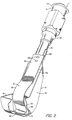
- a microsurgical stapling system comprising a manually operable driver 2 and a stapling tool or head 4 made in accordance with the present invention.
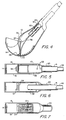
- Stapling head 4 comprises a tubular stem 6, a hollow housing 8 which contains most of the critical functioning parts of the head, and a curved laminar or leaf spring 10 for advancing a staple magazine 12 (Fig. 3) into position for dispensing the leading staple through an ejection slot formed in the bottom side of hollow housing 8.
- laminar spring 10 is attached to the hollow stem 6 through spot welds 28 (Figs. 2 and 5).
- Spring 10 has an S-shaped curvature, comprising a relatively flat portion 30 which lies against the hollow stem 6, a convexly curved section 32 which curves away from the hollow housing 8, a nearly flat section 34 which extends down toward ejection slot 22, and a concavely curved section 36 which turns upwardly along bottom wall 14.
- the forward end of spring 10 is reduced in width to form a tang 38 which engages and moves the staple magazine 12 as hereinafter described.
- hollow stem 6 has a hollow socket-like member 40 attached to its upper or outer end.
- the exterior of member 40 has a reduced diameter as shown at 41, resulting in a flange 43.
- the socket-like member 40 has a cylindrical axially-extending bore 42 which is counterbored as shown at 44.
- Bore 42 has the same diameter as the internal surface that defines axial bore 7 in stem 6.
- Slidably disposed within bores 7 and 42 is a plunger in the form of a ramrod 46.
- Adjacent its upper end the ramrod has a circular peripheral flange 48 sized to make a close sliding fit in counterbore 44.
- a return coil spring 52 Captivated between flange 48 and the tapered bottom end 50 of counterbore 44 is a return coil spring 52.
- Spring 52 is a compression spring and acts to urge ramrod 46 in an upward direction, as viewed in Fig. 3.
- driver 2 Attached to socket-like member 40 is driver 2 for applying a driving force F (see Figs. 2 and 3) to ramrod 46 against the force of return spring 52.
- Driver 2 may take various forms. Thus, as shown in Figs. 17 and 18, it may be a trigger type mechanism in which an axial force F is derived from the discharge of a pre-cocked spring released by operation of a trigger.
- driver means could be used, e.g. a pneumatically or electrically-powered driver.
- ramrod 46 has a flat recess 60 to accommodate the upper end of ram plate 58. The latter is welded or brazed to ramrod 46.
- ram plate 58 is wider than the outer diameter of stem 6, so that it projects from both sides of the diametrical slot 56.
- the bottom end of ram plate 58 is formed with two push lugs 62 that are spaced from one another.
- the bottom edges of lugs 62 are formed with circularly-curved channels 64 to allow the lugs to conform to the shape of the top portions of the staples 70 hereinafter described.
- the purpose of channels 64 is to prevent the staple which is being driven from slipping out of contact with lugs 62.
- the staple magazine 12 is formed from a flat sheet of a suitable material, preferably stainless steel, and consists of a plurality of staples 70 formed in a suitable manner, e.g. by die punching and forming. As illustrated in Figs. 8 and 9, the staples are part of a sheet continuum, each being disposed between side frame members 72 and 74 and cross frame members 76, and each having two tiny tabs 78 and 79 on one side joining it to cross frame members 76 and two tiny tabs 80 and 82 on its opposite side joining it to cross frame members 76. As seen in Figs. 8, 9, 12, 14 and 16, staples 70 are formed with a body or spine portion 83 and two convexly curved legs 84 and 85 that project above the plane of staple magazine 12.
- each leg of staples 70 are formed so that they diverge slightly from one another, e.g. each leg extends at an angle of approximately 15-20 degrees to the vertical (see Fig. 9).
- Magazine 12 has openings 73, 75, 77 and 81 which assist in defining staples 70, frame members 72, 74 and 76, and tabs 78, 79, 80 and 82.
- each staple magazine has a leading slot 90 that receives the forward end of spring 10, plus a leading end cross-member 92 that has a greater width than the cross frame members 76, in order to provide a better force distribution in response to the staple feeding action of spring 10.
- Tabs 78, 79, 80 and 82 may or may not be pre-sheared to facilitate proper separation of the staples 70 from magazine 12.
- the elastic force of spring 10 serves to feed the magazine toward bulkhead 24 every time that the ram plate 58 is retracted after a staple has been implanted.
- Each operation of ram plate 58 causes the staple magazine to be advanced a distance equal to the spacing between successive staples, with return spring 52 causing ramrod 46 to return to its original position.
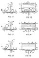
- Figures 11, 13, and 15 provide a side view in elevation of selected elements of the system of Figs. 1-9 in a typical surgical stapling operation, while Figs. 12, 14, and 16 show a cross-sectional view of the same stapling operation.
- the stapling head is shown positioned over an incision 98 in human tissue 100.
- the stapling head is in its at-rest position which is characterized by the upper end of ram plate 58 being engaged with the upper end of slot 56 in stem 6 (Fig. 3) and the lower end of the same plate being engaged with bulkhead 24 but spaced from magazine 12 (Fig. 4).
- Fig. 11 and 12 the stapling head is shown positioned over an incision 98 in human tissue 100.
- the stapling head is in its at-rest position which is characterized by the upper end of ram plate 58 being engaged with the upper end of slot 56 in stem 6 (Fig. 3) and the lower end of the same plate being engaged with bulkhead 24 but spaced from magazine 12 (Fig
- the stapler is placed so as to straddle the incision to insure that the two legs 84 and 85 of the staple to be implanted will grasp approximately the same amount of tissue at each side of the incision.
- the staple to be implanted i.e., the leading staple in the magazine
- the lower end of ram plate 58 is located directly above the staple 70A that is to be implanted.
- Leaf spring 10 urges staple magazine 12 toward the left in Fig. 11, thereby feeding the leading staple toward the gap formed between bulkhead 24 and bottom wall 14 and holding that leading staple against the bulkhead in alignment with ejection slot 22.
- the staple magazine stays in this position until staple 70A is ejected, whereupon spring 10 will advance the magazine to place the next staple against the bulkhead after ram plate 58 has been retracted.
- ram plate push lugs 62 engage the upper portion of convexly curved legs 84 and 85 of staple 70A so that those portions reside in ram plate channels 64 (Fig. 10).
- ram plate push lugs 62 deflect the two convex legs 84 and 85 of the staple downward, with the legs following a curved trajectory as they are driven into the tissue on both sides of the incision.
- Figs. 13 and 14 help illustrate what happens as ram plate 58 continues advancing downward, pushing staple 70A ahead of it.
- staple 70A is shown as it undergoes maximum deformation, which occurs just before it is sheared off from the magazine.
- the staple is deformed under the action of push lugs 62 so that its legs 84 and 85 follow an arc of trajectory as they penetrate the tissue.
- This action which is similar to the motion of a surgeon's suturing needle, is beneficial since it reduces the possibility and/or degree of stitching trauma.
- Figs. 13 and 14 show staple 70A almost fully implanted, with the two edges of the incision drawn firmly and evenly together, since they are both under the control of the bottom wall 14 of hollow body 8.
- Figs. 15 and 16 illustrate the final or shearing action.
- the downward stroke of ram plate 58 is limited, stopping when portion 59 of its bottom end has passed a short distance below the upper surface of bottom wall 14 at ejection slot 22, that distance being far enough below bottom wall 14 to sever tabs 78, 79, 80 and 82 by the shearing action previously described. Since the thickness of ram plate 58 (its width is its horizontal dimension as seen in Figs. 11, 13 and 15) is only slightly less than that of slot 22, there is virtually no space or gap remaining between those elements as the shearing of tabs 78, 79, 80 and 82 occurs.
- ram plate 58 actually depresses the tissue surface (see Fig. 16) so as to facilitate a substantially firm and flush alignment between the staple and the portions of the tissue that border on the incision.
- the present stapler also provides excellent control over the depth of penetration of the staple.
- the staple is inelastically deflected downward by ram plate 58.
- the staples 70 are finally sheared off from the magazine, they have already begun to pull upwardly from the tissue due to the edge-gathering forces resulting from their curving entry into the tissue.
- Driver 2 is designed to drive the staples with a velocity in excess of the ability of live tissues to react dynamically under the force of the penetrating staples, so as to make it unnecessary to hold and support the limp edges of some delicate tissues at the time of stapling.
- Driver 2 comprises two hollow tubular bodies 102 and 104.
- Tubular body 102 is closed off at one end by an end wall 106 and has a reduced diameter forward end section 108 that is threaded as shown so that it may be screwed into a tapped hole in the adjacent end of second hollow body 104.
- Hollow body 102 has a constant diameter bore 112.
- Hollow body 104 has a forward end surface 115 and a reduced diameter hollow front extension 116.
- Hollow body 104 is characterized by a constant diameter axial bore 120 that extends from the forward end of its extension 116 and is transformed into four counterbores 121, 122, 123, and 124. The latter is threaded to mate with hollow body 102.
- Front extension 116 has an outer diameter such that it will make a snug sliding fit in counterbore 44 of the stapler head (Fig. 3), while bore 120 is sized so as to make a close sliding fit around the outer end 47 of ramrod 46.
- the side wall of hollow body 104 is provided with an elongated flat-sided slot 128 for accomodating a clasp member 129.
- Slot 128 intersects forward end surface 115 and terminates a substantial distance short of the rear end surface 130 of hollow body 104 at a partition 131.
- Hollow body 104 has a second flat-sided slot 132 for accomodating a trigger member 133 and a trigger stop member 134.
- Slot 132 is located in diametric opposition to slot 128.
- Slot 132 extends from a point behind forward end surface 115 for approximately half the length of hollow body 104, and intersects counterbore 124.
- Hollow body 104 has a third slot 136 disposed in axial alignment with slot 128 for accommodating a pawl member 137. Slot 136 also intersects counterbore 124.
- a striker member 150 Disposed in bore 120 is a striker member 150.
- the latter has an enlarged head 152 having an outside diameter smaller than the diameters of counterbores 122 and 123.
- a compression spring 156 Surrounding striker member 150 is a compression spring 156 that urges the striker member toward counterbore 124.
- Spring 156 is engaged at one end with the shoulder formed by the junction of bore 120 and counterbore 121, while the opposite end of that spring engages head 152.
- Head 152 of striker 150 is engaged by the end of a ram member 160.
- Ram 160 has an enlarged head 162 at one end which engages a cylindrical inertia or weight member 166. The latter is engaged by a compression spring 170 that is disposed between weight 166 and the end wall 106, urging weight 166 away from end wall 106.
- ram 160 has a radially-extending finger 176 and an integral longitudinal extension 178, the latter being disposed eccentric to the center axis of the ram.
- Finger 176 has a catch 180 for engagement by a portion of pawl member 137, as hereinafter described.
- Ram extension 178 is notched as shown at 184 (Fig. 19) for engagement by a portion of trigger 133 as hereinafter described.
- Clasp 129 is pivotally secured to hollow body 104 by a pivot pin 188 (Fig. 19), while trigger member 133 and pawl member 137 are pivotally attached to hollow body 104 by pivot pins 189 and 190, respectively.
- a compression spring 192 disposed in blind holes in clasp 129 and hollow body 104, urges the clasp to the open position shown in Figs. 17, 19 and 20.
- a leaf spring 194 (Fig. 19) is brazed or welded in place in a shallow depression 195 in hollow body 104 that borders the slot 136.
- Leaf spring 194 bears against the long body portion 209 of pawl member 137 and urges it inwardly of the hollow body, i.e., so that it is urged in a counterclockwise direction as seen in Figs. 17, 19 and 20.
- Trigger 133 is generally L-shaped, comprising a first surgeon-engageable portion 196 and a ram actuating portion 198.
- Ram actuating portion 198 is provided with a hole 200 (Fig. 19) which is sized so as to make a loose fit with ram extension 178.
- a contoured leaf spring 204 has a first end portion 205 which engages the bottom of slot 132, and a folded back portion 206 which extends into hole 200 of trigger 133 and simultaneously engages the bottom surface of slot 132.
- the folded back portion 206 of spring 204 bears against the exterior surface of ram extension 178 so as to urge it downwardly (as viewed in Figs. 17, 19 and 20) toward pivot pin 190.
- the ram engaging portion 198 of trigger 133 is provided with a bevelled surface 208 which faces finger 176.
- Pawl member 137 comprises a long body portion 209 having a lateral extension 210 adjacent pivot pin 190. Lateral extension 210 extends adjacent to the bevelled surface 208 of trigger 133 when the latter and pawl member 137 are disposed in the driver's at-rest position shown in Fig. 19. Pawl member 137 also has a notch 214 at its free end for the purpose of making engagement with the catch portion of finger 176 when the driver is placed in cocking condition, as hereinafter described.
- Clasp 129 has a surface 216 which extends at an angle to a surface 220, both of said surfaces being flat for engagement with the flat surface 222 that forms the bottom of slot 128. Engagement of surface 220 with surface 222 determines the open position of the clasp member, while engagement of surface 216 with surface 222 determines the closed position of the clasp member.
- clasp member 129 At its free or forward end clasp member 129 is provided with a right angle extension 228 (Fig. 17) and also is slotted as shown at 230 (Figs. 17 and 18), whereby the forward end of the clasp member, including its right angle extension 228, is divided into two arms 234 and 236.
- the inner surfaces of arms 234 and 236 are contoured so as to have circularly curved confronting surfaces 238 and 240.
- the radius of curvature of each of the surfaces 238 and 240 is substantially the same as that of the exterior of surface 41 of socket-like member 40 (Fig. 2).
- Surfaces 234 and 236 extend far enough to be mutually converging where they intersect the flat end surfaces 239 of the free ends of the two arms, i.e., the end surfaces 239 of the free forward extremities of arms 234 and 236 are spaced from one another a distance less than the radius of curvature of surfaces 238 and 240.
- the stapler head of Figs. 1-10 is attached to the driver by inserting the driver's tubular extension 116 (Fig. 17) into axial counterbore 44 of the stapler's socket-like member 40 (Fig. 3).
- the socket-like member 40, its counterbore 44, striker 150 and extension 116 have lengths such that when extension 116 is inserted into socket-like member 40, striker 150 will lightly contact ramrod 46 and flange 43 will be spaced from end surface 115 of driver 2.
- clasp 129 is pivoted clockwise as seen in Fig. 17, forcing its arms 234 and 236 to engage the circularly-curved outer surface 41 of the stapler head.
- arms 234 and 236 are resilient, under the pivoting force they will spring apart to pass around the reduced diameter section 41 of the stapler head. The resiliency of arms 234 and 236 then will automatically cause them to compress against outer surface 41, locking the stapler head to the driver. Removal of the stapler head from the driver is achieved by the operator's pressing of bump or projection 244 (Fig. 19), which in turn will cause clasp 129 to pivot counterclockwise (as viewed in Figs. 17 and 19) out of contact with socket-like member 40.
- the driver is cocked by depressing trigger 133 once, i.e., pivoting it counterclockwise as seen in Fig. 17, until it engages trigger stop member 134.
- trigger 133 As trigger 133 is depressed, its extension 198 engages the shoulder formed by notch 184 in ram extension 178 and forces ram member 160 to the right (as seen in Figs. 17, 19 and 20), forcing inertia weight 166 to compress spring 170.
- Ram 160 is moved to the right far enough to position finger 176 beyond notch 214 in pawl 137, whereupon leaf spring 194 will force pawl 137 to pivot counterclockwise (as seen in Fig. 17) inwardly far enough for notch 214 of pawl 137 to engage catch 180 of ram member 160. Thereafter, when trigger 133 is released, spring 170 will urge ram member 160 to the left (as seen in Fig.
- ram extension 178 may or may not be engaged by head 152 of striker 150, depending on the axial position of striker 150. In any case, it is to be appreciated that spring 156 does not actively bias striker head 152 against the retracted ram extension. See Fig. 20.
- Firing of the cocked driver is achieved by depressing trigger 133 a second time.
- the lateral portion 198 of trigger 133 will force ram member 160 further out of alignment with the oversized bore 112 of hollow body 102, i.e., the extension 178 of ram member 160 is moved further upwardly against folded back portion 206 of spring 204 (as seen in Figs. 17, 19 and 20), thereby disengaging catch 180 from the notched portion 214 of pawl member 137, whereupon the ram will be driven forward by inertia weight 166 acting under the force of spring 170.
- ram extension 178 will impact against head 152 of striker 150, driving the latter forward along bore 120.
- striker 150 will engage ramrod 46 of the stapler head, causing the ramrod to drive ram plate 58 downwardly to cause a staple to be discharged in the manner previously described.
- the driver shown in Figs. 17-20 offers the advantage that it is compact, easy to hold and use, and can be arranged to cause ram plate 58 to drive staples 70 with a velocity substantially in excess of the ability of live tissues to react dynamically under the force of the penetrating staples, so as to make it unnecessary to hold together the limp edges of delicate tissues at the time of stapling.
- the latter advantage is very significant when using the stapling system to suture sensitive tissue, e.g. in ophthalmic or cosmetic surgery procedures.
- Further advantages are that the staples are positively positioned in line with ejection slot 22, thereby reducing the possibility of jamming or misfiring, and the stapler head is easily replaced by a new one when its supply of staples has been exhausted.
- each staple 70 to the surrounding frame members may be varied, so that, for example, each staple may be held at its leading or trailing side by one, two or more tabs, and the number of tabs on one side may or may not be equal to the number of tabs on the opposite side.
- the number of staples in the magazine may be varied.
- the shape of the staples may be varied somewhat from that shown in Fig. 9.
- the staples generally comprise a substantially straight body section and a pair of curved legs, it is possible to form the legs with something other than a "continuous" curvature.
- Fig. 9A illustrates such an alternative staple design. More specifically, the staple shown in Fig. 9A is identical to the staple shown in Fig. 9, except that each of the legs 84a, 85a of the staple of Fig. 9A is distinctly bent at two different points along the length of the leg, rather than being more or less “continuously” rounded as is the case with the legs of the staple of Fig. 9.
- the stapler head shown is designed to be discarded when all of the staples in magazine 12 have been used, it is contemplated that the stapler head may be modified to provide for replacing an empty magazine with a full magazine 12. Also a driver different from driver 2 may be used with the stapling head of this invention.
- leaf spring 10 may be replaced by a coil spring 500 (Fig. 21) which has its interior end 502 attached to a crossbar 504 which extends between the stapler head's opposite side walls 16 and 18 (Fig. 2) and which has its exterior end 506 attached to the leading end of staple magazine 12.
- spring 170 and weight 166 may be reversed, i.e., so that weight 166 engages end wall 106 and spring 170 engages the enlarged head 162 of ram 160.
- Such a construction will reduce the inertia to be overcome by spring 170 when driving ram 160 forward, thereby allowing the ram (and hence the staple) to be driven at a higher velocity.
Abstract
Description
- This invention relates particularly but not exclusively to new and improved methods and apparatus for the suturing of delicate tissues by means of fine wire staples.
- In a first aspect, the present invention relates to a stapler, defined below in a claim in which the prior art portion is based on the stapler of US-A-2174708. In a second aspect, the present invention is embodied in a sheet metal multi-staple magazine, and such a magazine of staples is also disclosed in US-A-2174708. A third aspect of the invention lies in an anvil-less stapling method. The method of US-A-2174708 is conventional, using an anvil.
- Suturing is a very time consuming phase of most surgical operations. Heretofore it has been realized that suturing time can be reduced considerably by the use of stapling techniques. As a consequence, in recent years several types of stapling systems have come into use for surgical suturing.
- By way of example, the following U.S. patents illustrate the various types of staplers which have been used for suturing purposes: 3604561, 3646801, 4162678, 4316468, 4317451 and 4485816, and the references cited therein.
- However, prior surgical stapling systems suffer from a variety of disadvantages, including but not limited to: (1) excessive size for the intended application; (2) the need to bend the staples across the tissue, which induces severe traumatic effects; (3) the need to extract the stapler anvil from the tissue surface after the staples have been implanted; and (4) inability to maintain precise edge alignment and smoothness as required in ophthalmic and cosmetic surgery. As a consequence, prior medical staplers have been unsuitable for delicate ophthalmic surgical operations where only an absolute minimum of trauma may be induced during the surgical procedure.
- The present invention has as its primary object the provision of a stapler for the suturing of very delicate tissue incisions such as those involved in ophthalmic operations, neurosurgery, or plastic surgery.
- A more specific object of the invention is to provide a new and improved surgical suturing microstapler system which is characterized by the use of very fine metallic staples made of a stainless steel alloy that is non-injurious to human tissues.
- Another specific object of the invention is to provide a microstapler suturing system that is adapted to implant staples with a minimum of trauma, with the implanted staples providing at least the same holding strength as that obtainable with commonly used flexible filament sutures.
- Still another object of the invention is to provide a surgical stapling system having pre-shaped staples which are held together in a magazine strip from which they are sheared cleanly after they have penetrated tissue so as to hold together the sides of an incision.
- Still another object of the invention is to provide a microsurgical stapling system in which the staples are driven with a velocity in excess of the ability of live tissues to react dynamically under the force of the penetrating staples, so as to make it unnecessary to hold the limp edges of some delicate tissues at the time of stapling.
- Still another object of the invention is to provide a stapler-type suturing system which is designed to suture together delicate tissues in a manner which reduces trauma to a minimum and assures proper incision alignment, as is essential for ophthalmic or plastic suturing where incision stresses can induce post-operative deformations such as astigmatism or scarring.
- A further object of the invention is to provide a stapling system having staples which are shaped as close as possible to the atraumatic curvature best suited to reduce tissue pull and tear during penetration.
- Still another object of the invention is to provide a microsurgical stapling system which does not require the use of a staple-bending anvil that must be retracted after the staple is implanted.
- In a first aspect, the invention provides a stapler distinguished by the characterising features of claim 1 below.
- In a second aspect, the invention provides a sheet metal, multi-staple magazine as claimed in claim 17 below.
- In a third aspect, the invention provides an anvil-less stapling method according to claim 27 below.
- In the preferred embodiment of the invention, the staple magazine is formed from a stainless steel sheet and consists of a series of staples attached to and supported by a plurality of frame members. The staples are formed by die punching, chemical etching, or some other convenient method well known to persons skilled in the art. The staples have a predetermined shape characterized by a spine or body portion and two opposite legs. The staples and frame members are formed as part of a sheet metal continuum and are joined by a plurality of tiny tabs which coact with the frame members to hold the staples in proper spaced relationship within the magazine.
- The new stapler head comprises means for holding and advancing the staple magazine so that the leading staple in the magazine is positioned in a predetermined dispensing position. The stapler head has an ejection slot through which a staple located in the predetermined dispensing position is ejected and inserted into the tissue to be sutured. The tool further includes staple driving means for engaging the leading staple and implanting it into the tissue through the ejection slot. The staple is held to the magazine at its spine as it is engaged by the staple driving means. The latter is shaped so as to contact the opposite legs of the staple and to deflect them downward following a curved trajectory inside the tissue. As the staple driving means continues advancing downward, causing the staple legs to be bent and to penetrate the tissue around an arc of trajectory which closely resembles the motion of a surgeon's suturing needle, the tabs are sheared against the edge of the ejection slot by portions of the staple driving means, freeing the staple from the magazine and leaving it implanted in the tissue. The unique shearing action of the new stapler system eliminates the need for an anvil.
- Other features and advantages of the invention are described or rendered obvious by the following detailed description of a preferred embodiment of the invention, which is to be considered together with the accompanying drawings.
-
- Fig. 1 is a side view in elevation of a stapling head made in accordance with this invention, in combination with a preferred driver;
- Fig. 2 is an enlarged perspective view of the same stapling head;
- Fig. 3 is a view similar to Fig. 2, but with certain portions broken away, illustrating the disposition of the staple magazine within the stapler head;
- Fig. 4 is a side elevation, partly in section, illustrating the disposition of the staple magazine within the stapler head;
- Fig. 5 is a plan view of the stapler head;
- Fig. 6 is a plan view of the stapler head with the magazine feed spring member removed;
- Fig. 7 is a further plan view of the stapler head with additional elements removed;
- Fig. 8 is a plan view of a preferred form of staple magazine in an uncurved state;
- Fig. 9 is a sectional view of the staple magazine taken along line 9-9 of Fig. 8;
- Fig. 9A is a sectional view of an alternative form of staple magazine, illustrating an alternative staple design;
- Fig. 10 is a fragmentary cross-sectional view taken along line 10-10 of Fig. 12 illustrating channels formed in the push lugs of
ram plate 58; - Figs. 11, 13 and 15 are fragmentary longitudinal sectional views illustrating operation of the new stapler head under the influence of the attached driver;
- Figs. 12, 14 and 16 are cross-sectional views, corresponding to Figs. 11, 13 and 15 respectively, illustrating operation of the stapler head;
- Fig. 17 is an enlarged longitudinal sectional view of the driver shown in Fig. 1;
- Fig. 18 is an end view of the same driver;
- Figs. 19 and 20 are enlarged fragmentary longitudinal sectional views illustrating operation of the driver; and
- Fig. 21 is a partial side elevation, partly in section, illustrating an alternative form of stapler head.
- Referring now to Figs. 1-7, there is shown a microsurgical stapling system comprising a manually operable driver 2 and a stapling tool or head 4 made in accordance with the present invention. Stapling head 4 comprises a
tubular stem 6, ahollow housing 8 which contains most of the critical functioning parts of the head, and a curved laminar orleaf spring 10 for advancing a staple magazine 12 (Fig. 3) into position for dispensing the leading staple through an ejection slot formed in the bottom side ofhollow housing 8. - As shown in Figs. 1-7,
hollow housing 8 is formed with acurved bottom wall 14 andopposite side walls shaped channel section 20 that embraces and is welded or otherwise fastened to stem 6. A staple ejection slot 22 (Fig. 4) is formed inbottom wall 14.Hollow housing 8 also is provided with aninternal bulkhead 24 that is attached toside walls bottom wall 14. - Preferably
laminar spring 10 is attached to thehollow stem 6 through spot welds 28 (Figs. 2 and 5).Spring 10 has an S-shaped curvature, comprising a relativelyflat portion 30 which lies against thehollow stem 6, a convexlycurved section 32 which curves away from thehollow housing 8, a nearlyflat section 34 which extends down towardejection slot 22, and a concavelycurved section 36 which turns upwardly alongbottom wall 14. The forward end ofspring 10 is reduced in width to form atang 38 which engages and moves thestaple magazine 12 as hereinafter described. - Referring to Figs. 2 and 3,
hollow stem 6 has a hollow socket-like member 40 attached to its upper or outer end. The exterior ofmember 40 has a reduced diameter as shown at 41, resulting in aflange 43. The socket-like member 40 has a cylindrical axially-extending bore 42 which is counterbored as shown at 44. Bore 42 has the same diameter as the internal surface that definesaxial bore 7 instem 6. Slidably disposed withinbores 7 and 42 is a plunger in the form of aramrod 46. Adjacent its upper end the ramrod has a circularperipheral flange 48 sized to make a close sliding fit incounterbore 44. Captivated betweenflange 48 and the taperedbottom end 50 ofcounterbore 44 is areturn coil spring 52.Spring 52 is a compression spring and acts to urgeramrod 46 in an upward direction, as viewed in Fig. 3. - Attached to socket-
like member 40 is driver 2 for applying a driving force F (see Figs. 2 and 3) to ramrod 46 against the force ofreturn spring 52. Driver 2 may take various forms. Thus, as shown in Figs. 17 and 18, it may be a trigger type mechanism in which an axial force F is derived from the discharge of a pre-cocked spring released by operation of a trigger. However, other driver means could be used, e.g. a pneumatically or electrically-powered driver. - The bottom end of hollow
tubular stem 6 extends intohousing 8 and is slotted along a diameter as shown at 56 (Fig. 3) to accommodate aram plate 58 that has a curvature as shown in Fig. 4 and is secured to the bottom end oframrod 46. For this purpose, ramrod 46 has aflat recess 60 to accommodate the upper end ofram plate 58. The latter is welded or brazed to ramrod 46. As seen in Figs. 2 and 3,ram plate 58 is wider than the outer diameter ofstem 6, so that it projects from both sides of thediametrical slot 56. With this arrangement, rectilinear axial motion oframrod 46 andram plate 58 relative to stem 6 is permitted, while rotational axial motion oframrod 46 relative to stem 6 is prevented by the interaction ofram plate 58 with the portions ofstem 6 that defineslot 56. Also the depth ofslot 56 determines the extent of rearward motion ofram plate 58, since the edge surfaces ofstem 6 that determine the depth ofslot 56 act as a stop forram plate 58. - As seen best in Figs. 3 and 4,
ram plate 58 is flat where it is attached to the ramrod, but its forward half is curved downwardly. The curvature ofplate 58 is set so that its forward end (the bottom end as seen in Fig. 4) extends down at substantially a right angle tobottom wall 14 ofhousing 8. Also the ram plate is made long enough so that its forward end is substantially parallel to and engagesbulkhead 24 when the ram plate is in its retracted position (Fig. 4). - As seen best in Fig. 12, the bottom end of
ram plate 58 is formed with two push lugs 62 that are spaced from one another. As seen in Fig. 10, the bottom edges oflugs 62 are formed with circularly-curved channels 64 to allow the lugs to conform to the shape of the top portions of thestaples 70 hereinafter described. The purpose ofchannels 64 is to prevent the staple which is being driven from slipping out of contact withlugs 62. - The
staple magazine 12 is formed from a flat sheet of a suitable material, preferably stainless steel, and consists of a plurality ofstaples 70 formed in a suitable manner, e.g. by die punching and forming. As illustrated in Figs. 8 and 9, the staples are part of a sheet continuum, each being disposed betweenside frame members cross frame members 76, and each having twotiny tabs frame members 76 and twotiny tabs frame members 76. As seen in Figs. 8, 9, 12, 14 and 16,staples 70 are formed with a body orspine portion 83 and two convexlycurved legs staple magazine 12. The legs ofstaples 70 are formed so that they diverge slightly from one another, e.g. each leg extends at an angle of approximately 15-20 degrees to the vertical (see Fig. 9).Magazine 12 hasopenings staples 70,frame members tabs slot 90 that receives the forward end ofspring 10, plus aleading end cross-member 92 that has a greater width than thecross frame members 76, in order to provide a better force distribution in response to the staple feeding action ofspring 10.Tabs staples 70 frommagazine 12. - The elastic force of
spring 10 serves to feed the magazine towardbulkhead 24 every time that theram plate 58 is retracted after a staple has been implanted. Each operation ofram plate 58 causes the staple magazine to be advanced a distance equal to the spacing between successive staples, withreturn spring 52 causingramrod 46 to return to its original position. - As seen in Fig. 4, when the
ramrod 46 is in its relaxed or raised position, the push lugs 62 ofram plate 58 are in a retracted position relative tostaple magazine 12. - The mode of operation of the system is illustrated in Figs. 11-16.
- Figures 11, 13, and 15 provide a side view in elevation of selected elements of the system of Figs. 1-9 in a typical surgical stapling operation, while Figs. 12, 14, and 16 show a cross-sectional view of the same stapling operation. Referring first to Figs. 11 and 12, the stapling head is shown positioned over an
incision 98 inhuman tissue 100. At this time the stapling head is in its at-rest position which is characterized by the upper end ofram plate 58 being engaged with the upper end ofslot 56 in stem 6 (Fig. 3) and the lower end of the same plate being engaged withbulkhead 24 but spaced from magazine 12 (Fig. 4). As seen in Fig. 12, the stapler is placed so as to straddle the incision to insure that the twolegs magazine 12. The lower end ofram plate 58 is located directly above thestaple 70A that is to be implanted.Leaf spring 10 urgesstaple magazine 12 toward the left in Fig. 11, thereby feeding the leading staple toward the gap formed betweenbulkhead 24 andbottom wall 14 and holding that leading staple against the bulkhead in alignment withejection slot 22. The staple magazine stays in this position untilstaple 70A is ejected, whereuponspring 10 will advance the magazine to place the next staple against the bulkhead afterram plate 58 has been retracted. - Assume that the surgeon now actuates driver 2 so as to cause
ram plate 58 to be driven downwardly. As this occurs, ram plate push lugs 62 engage the upper portion of convexlycurved legs staple 70A so that those portions reside in ram plate channels 64 (Fig. 10). Downward motion ofram plate 58 drivesstaple 70A downward so as to cause it to be sheared off fromstaple magazine 12. At the same time, push lugs 62 deflect the twoconvex legs channels 64 with the upper portions oflegs staple 70A assures that the staple will not slide out from under ram plate lugs 62, whereby the staple is stabilized in the downward direction and prevented from squirming away from the control ofram plate 58 and its push lugs 62. The staple is guided during its downward motion by virtue of the fact that it remains engaged withbulkhead 24 until it is sheared off from its leadingtabs tabs 80 and 82 (Fig. 8). As the staple moves down into and throughejection slot 22, downward movement oftabs bottom wall 14 that defineejection slot 22, with the result that further downward action ofram plate 58 causes those tabs to be sheared off from the staple. In this shearing action, thecenter portion 59 of the bottom end ofram plate 58 that extends betweenlugs 62 acts as a shear blade against the edges ofejection slot 22. - Figs. 13 and 14 help illustrate what happens as
ram plate 58 continues advancing downward, pushingstaple 70A ahead of it. In these figures,staple 70A is shown as it undergoes maximum deformation, which occurs just before it is sheared off from the magazine. As seen in Fig. 14, the staple is deformed under the action of push lugs 62 so that itslegs show staple 70A almost fully implanted, with the two edges of the incision drawn firmly and evenly together, since they are both under the control of thebottom wall 14 ofhollow body 8. - Figs. 15 and 16 illustrate the final or shearing action. The downward stroke of
ram plate 58 is limited, stopping whenportion 59 of its bottom end has passed a short distance below the upper surface ofbottom wall 14 atejection slot 22, that distance being far enough belowbottom wall 14 to severtabs slot 22, there is virtually no space or gap remaining between those elements as the shearing oftabs staple 70A,ram plate 58 actually depresses the tissue surface (see Fig. 16) so as to facilitate a substantially firm and flush alignment between the staple and the portions of the tissue that border on the incision. - The result is a solution long sought by surgeons. The two legs of
staple 70A move in a true, or nearly true, circular arc about the pivot points represented bytabs ram plate 58 occurring while the staple is still attached firmly to the staple magazine. - The result is virtually absolute control of the implantation of the staple and a minimization of trauma caused by improper alignment and/or direction of the implanted staple. It is to be appreciated that the present stapler also provides excellent control over the depth of penetration of the staple.
- It is to be noted that at the time of implantation of a staple 70, the staple is inelastically deflected downward by
ram plate 58. When thestaples 70 are finally sheared off from the magazine, they have already begun to pull upwardly from the tissue due to the edge-gathering forces resulting from their curving entry into the tissue. - When a staple 70 is sheared off, its body or
spine 83 will snap down against the surface of the tissue, thereby causing the staple to remain substantially flush with the tissue. When that occurs, the internal stresses imposed by the edge-gathering forces tend to disappear andincision 98 will remain perfectly closed but with a minimum of internal stressses and trauma. - The results and effects described above are obtained consistently and reliably with the present invention, in contrast with the great variability and uncertainty that characterizes present incision-closing techniques, especially those used in ophthalmology, where incision and suture sizes are extremely small and surgeons must depend on surgical microscopes for making and suturing incisions.
- Turning now to Figs. 1 and 17-20, there is shown a preferred form of driver 2 for operating the stapler described above. Driver 2 is designed to drive the staples with a velocity in excess of the ability of live tissues to react dynamically under the force of the penetrating staples, so as to make it unnecessary to hold and support the limp edges of some delicate tissues at the time of stapling.
- Driver 2 comprises two hollow
tubular bodies Tubular body 102 is closed off at one end by anend wall 106 and has a reduced diameter forward end section 108 that is threaded as shown so that it may be screwed into a tapped hole in the adjacent end of secondhollow body 104.Hollow body 102 has aconstant diameter bore 112.Hollow body 104 has aforward end surface 115 and a reduced diameter hollowfront extension 116.Hollow body 104 is characterized by a constant diameteraxial bore 120 that extends from the forward end of itsextension 116 and is transformed into fourcounterbores hollow body 102.Front extension 116 has an outer diameter such that it will make a snug sliding fit incounterbore 44 of the stapler head (Fig. 3), whilebore 120 is sized so as to make a close sliding fit around theouter end 47 oframrod 46. - The side wall of
hollow body 104 is provided with an elongated flat-sided slot 128 for accomodating aclasp member 129.Slot 128 intersectsforward end surface 115 and terminates a substantial distance short of therear end surface 130 ofhollow body 104 at a partition 131.Hollow body 104 has a second flat-sided slot 132 for accomodating atrigger member 133 and atrigger stop member 134.Slot 132 is located in diametric opposition to slot 128.Slot 132 extends from a point behindforward end surface 115 for approximately half the length ofhollow body 104, and intersectscounterbore 124.Hollow body 104 has athird slot 136 disposed in axial alignment withslot 128 for accommodating apawl member 137. Slot 136 also intersectscounterbore 124. - Disposed in
bore 120 is astriker member 150. The latter has anenlarged head 152 having an outside diameter smaller than the diameters ofcounterbores striker member 150 is acompression spring 156 that urges the striker member towardcounterbore 124.Spring 156 is engaged at one end with the shoulder formed by the junction ofbore 120 andcounterbore 121, while the opposite end of that spring engageshead 152.Head 152 ofstriker 150 is engaged by the end of aram member 160.Ram 160 has anenlarged head 162 at one end which engages a cylindrical inertia orweight member 166. The latter is engaged by acompression spring 170 that is disposed betweenweight 166 and theend wall 106, urgingweight 166 away fromend wall 106. - The forward end of
ram 160 has a radially-extendingfinger 176 and an integrallongitudinal extension 178, the latter being disposed eccentric to the center axis of the ram.Finger 176 has acatch 180 for engagement by a portion ofpawl member 137, as hereinafter described.Ram extension 178 is notched as shown at 184 (Fig. 19) for engagement by a portion oftrigger 133 as hereinafter described. -
Clasp 129 is pivotally secured tohollow body 104 by a pivot pin 188 (Fig. 19), whiletrigger member 133 andpawl member 137 are pivotally attached tohollow body 104 bypivot pins compression spring 192, disposed in blind holes inclasp 129 andhollow body 104, urges the clasp to the open position shown in Figs. 17, 19 and 20. Additionally a leaf spring 194 (Fig. 19) is brazed or welded in place in ashallow depression 195 inhollow body 104 that borders theslot 136.Leaf spring 194 bears against thelong body portion 209 ofpawl member 137 and urges it inwardly of the hollow body, i.e., so that it is urged in a counterclockwise direction as seen in Figs. 17, 19 and 20. -
Trigger 133 is generally L-shaped, comprising a first surgeon-engageable portion 196 and aram actuating portion 198.Ram actuating portion 198 is provided with a hole 200 (Fig. 19) which is sized so as to make a loose fit withram extension 178. A contouredleaf spring 204 has afirst end portion 205 which engages the bottom ofslot 132, and a foldedback portion 206 which extends intohole 200 oftrigger 133 and simultaneously engages the bottom surface ofslot 132. The folded backportion 206 ofspring 204 bears against the exterior surface ofram extension 178 so as to urge it downwardly (as viewed in Figs. 17, 19 and 20) towardpivot pin 190. Theram engaging portion 198 oftrigger 133 is provided with abevelled surface 208 which facesfinger 176. -
Pawl member 137 comprises along body portion 209 having alateral extension 210adjacent pivot pin 190.Lateral extension 210 extends adjacent to thebevelled surface 208 oftrigger 133 when the latter andpawl member 137 are disposed in the driver's at-rest position shown in Fig. 19.Pawl member 137 also has anotch 214 at its free end for the purpose of making engagement with the catch portion offinger 176 when the driver is placed in cocking condition, as hereinafter described. -
Clasp 129 has asurface 216 which extends at an angle to asurface 220, both of said surfaces being flat for engagement with theflat surface 222 that forms the bottom ofslot 128. Engagement ofsurface 220 withsurface 222 determines the open position of the clasp member, while engagement ofsurface 216 withsurface 222 determines the closed position of the clasp member. - At its free or forward
end clasp member 129 is provided with a right angle extension 228 (Fig. 17) and also is slotted as shown at 230 (Figs. 17 and 18), whereby the forward end of the clasp member, including itsright angle extension 228, is divided into twoarms 234 and 236. The inner surfaces ofarms 234 and 236 are contoured so as to have circularly curved confrontingsurfaces surfaces surface 41 of socket-like member 40 (Fig. 2).Surfaces 234 and 236 extend far enough to be mutually converging where they intersect the flat end surfaces 239 of the free ends of the two arms, i.e., the end surfaces 239 of the free forward extremities ofarms 234 and 236 are spaced from one another a distance less than the radius of curvature ofsurfaces - The stapler head of Figs. 1-10 is attached to the driver by inserting the driver's tubular extension 116 (Fig. 17) into
axial counterbore 44 of the stapler's socket-like member 40 (Fig. 3). The socket-like member 40, itscounterbore 44,striker 150 andextension 116 have lengths such that whenextension 116 is inserted into socket-like member 40,striker 150 will lightly contactramrod 46 andflange 43 will be spaced fromend surface 115 of driver 2. Thereafter clasp 129 is pivoted clockwise as seen in Fig. 17, forcing itsarms 234 and 236 to engage the circularly-curvedouter surface 41 of the stapler head. Becausearms 234 and 236 are resilient, under the pivoting force they will spring apart to pass around the reduceddiameter section 41 of the stapler head. The resiliency ofarms 234 and 236 then will automatically cause them to compress againstouter surface 41, locking the stapler head to the driver. Removal of the stapler head from the driver is achieved by the operator's pressing of bump or projection 244 (Fig. 19), which in turn will causeclasp 129 to pivot counterclockwise (as viewed in Figs. 17 and 19) out of contact with socket-like member 40. - Operation of the driver will now be described.
- Assuming that the stapling head of Figs. 1-10 is mounted on the front end of driver 2 and locked in place by
clasp 129, the driver is cocked by depressingtrigger 133 once, i.e., pivoting it counterclockwise as seen in Fig. 17, until it engagestrigger stop member 134. Astrigger 133 is depressed, itsextension 198 engages the shoulder formed bynotch 184 inram extension 178 and forces rammember 160 to the right (as seen in Figs. 17, 19 and 20), forcinginertia weight 166 to compressspring 170.Ram 160 is moved to the right far enough to positionfinger 176 beyondnotch 214 inpawl 137, whereuponleaf spring 194 will forcepawl 137 to pivot counterclockwise (as seen in Fig. 17) inwardly far enough fornotch 214 ofpawl 137 to engagecatch 180 ofram member 160. Thereafter, whentrigger 133 is released,spring 170 will urgeram member 160 to the left (as seen in Fig. 17), causingpawl 137 to pivot counterclockwise about itspivot pin 190 untilextension 210 engages partition 131, whereupon ram 160 moves out of alignment with the internaloversized bore 112 ofhollow body 102, unhookingtrigger portion 198 from ram notch 184 (as used in this context, "out of alignment" means that the left hand end ofram member 160 is shifted upwardly in Figs. 17, 19 and 20). At the same time, the free end of theportion 198 oftrigger 133 will have intruded behind and be locked by thelateral extension 210 of pawl 137 (Fig. 20). - At this point the forward end of
ram extension 178 may or may not be engaged byhead 152 ofstriker 150, depending on the axial position ofstriker 150. In any case, it is to be appreciated thatspring 156 does not actively biasstriker head 152 against the retracted ram extension. See Fig. 20. - Firing of the cocked driver is achieved by depressing trigger 133 a second time. When this occurs, the
lateral portion 198 oftrigger 133 will forceram member 160 further out of alignment with theoversized bore 112 ofhollow body 102, i.e., theextension 178 ofram member 160 is moved further upwardly against folded backportion 206 of spring 204 (as seen in Figs. 17, 19 and 20), thereby disengagingcatch 180 from the notchedportion 214 ofpawl member 137, whereupon the ram will be driven forward byinertia weight 166 acting under the force ofspring 170. As a consquence,ram extension 178 will impact againsthead 152 ofstriker 150, driving the latter forward alongbore 120. As it is propelled forward,striker 150 will engage ramrod 46 of the stapler head, causing the ramrod to driveram plate 58 downwardly to cause a staple to be discharged in the manner previously described. - At the same time forward movement of
ram member 160 will cause itsfinger 176 to slide along the inner surface ofpawl 137, thereby cammingpawl 137 in a clockwise direction (when viewed from the direction of Figs. 17, 19 and 20) back to its original at-rest position, whereby on release oftrigger 133, the trigger'slateral extension 198 is free to swing back to the position shown in Figs. 17 and 19 without interference by thelateral extension 210 ofpawl 137. At this point driver 2 is ready to be cocked again in preparation for implanting of another staple. - The driver shown in Figs. 17-20 offers the advantage that it is compact, easy to hold and use, and can be arranged to cause
ram plate 58 to drivestaples 70 with a velocity substantially in excess of the ability of live tissues to react dynamically under the force of the penetrating staples, so as to make it unnecessary to hold together the limp edges of delicate tissues at the time of stapling. The latter advantage is very significant when using the stapling system to suture sensitive tissue, e.g. in ophthalmic or cosmetic surgery procedures. Further advantages are that the staples are positively positioned in line withejection slot 22, thereby reducing the possibility of jamming or misfiring, and the stapler head is easily replaced by a new one when its supply of staples has been exhausted. - Obviously the apparatus herein described may be modified in various ways without departing from the essential principles of the invention. Thus the number of tabs holding each staple 70 to the surrounding frame members may be varied, so that, for example, each staple may be held at its leading or trailing side by one, two or more tabs, and the number of tabs on one side may or may not be equal to the number of tabs on the opposite side. Similarly, the number of staples in the magazine may be varied.
- It is also contemplated that the shape of the staples may be varied somewhat from that shown in Fig. 9. Thus, while the staples generally comprise a substantially straight body section and a pair of curved legs, it is possible to form the legs with something other than a "continuous" curvature. Fig. 9A illustrates such an alternative staple design. More specifically, the staple shown in Fig. 9A is identical to the staple shown in Fig. 9, except that each of the
legs - Furthermore, while the stapler head shown is designed to be discarded when all of the staples in
magazine 12 have been used, it is contemplated that the stapler head may be modified to provide for replacing an empty magazine with afull magazine 12. Also a driver different from driver 2 may be used with the stapling head of this invention. - Furthermore, the manner of advancing
staple magazine 12 within stapler head 4 may be changed. Thus, for example,leaf spring 10 may be replaced by a coil spring 500 (Fig. 21) which has itsinterior end 502 attached to acrossbar 504 which extends between the stapler head'sopposite side walls 16 and 18 (Fig. 2) and which has itsexterior end 506 attached to the leading end ofstaple magazine 12. - It is also to be appreciated that the relative positions of
spring 170 andweight 166 may be reversed, i.e., so thatweight 166 engagesend wall 106 andspring 170 engages theenlarged head 162 ofram 160. Such a construction will reduce the inertia to be overcome byspring 170 when drivingram 160 forward, thereby allowing the ram (and hence the staple) to be driven at a higher velocity. - Still other advantages, modifications and uses will be obvious to persons skilled in the art.
Claims (27)
- A stapler comprising a stapling mechanism (4) and a magazine (12) of integrally formed staples (70) aligned in series, each such staple having a pair of piercing legs (84, 85) linked by an elongate body portion (83) and capable of bending from an open disposition to a closed disposition, the stapling mechanism comprising a first wall surface (14) over which the magazine slides, a second wall surface (24) which extends at an angle to the first wall adjacent an ejection slot (22) in the first wall surface, magazine advancing means (10) for urging the magazine to advance over the first wall surface towards the slot and staple actuation means (58) to engage a leading staple of the magazine to sever the staple from the magazine and eject the staple through the slot;
the stapler being characterised in that:i. the staple magazine (12) and the actuation means (58) are so constructed and arranged that the actuation means acts (62) on the legs so as to cause the legs (84, 85) to bend relative to the central portion of the leading staple from their open to their closed disposition in the absence of any anvil, and in that:ii. the magazine comprises a sheet from which the staples are formed, and separated from the surrounding sheet by tabs (78, 79, 80, 82) adapted to survive the said bending of the legs of the staple yet thereafter yield with continued pressure of the actuation means on the staple so as to shear off the closed staple from the magazine. - A stapler as claimed in claim 1 wherein the free ends of the legs of the staples are in diverging relation to each other.
- A stapler as claimed in claim 1 or 2 wherein the magazine comprises a planar frame (72, 74, 76) for the staples (70).
- A stapler as claimed in claim 3 in which the legs (84, 85) of the staples extend out of the plane of the frame.
- A stapler as claimed in claim 4 in which the legs lie in a plane which itself is perpendicular to the plane of the frame.
- A stapler as claimed in claim 4 or 5 in which the legs are arcuate.
- A stapler as claimed in any one of claims 3 to 6 in which the free ends of the staple legs lie in the plane of the frame.
- A stapler according to any one of the preceding claims, characterised in that the staple actuation means comprises a pair of push lugs (62) formed on a ram plate (58) arranged so that edge portions of the ram plate co-operate with the staple ejection slot to shear off the leading staple from the magazine.
- A stapler according to claim 8, which includes means (46) for reciprocating the ram plate along the second wall into and out of the ejection slot.
- A stapler according to any one of the preceding claims, wherein the magazine has a drive slot (90) therein and the means for urging the magazine to advance along the first wall comprises a member (38) that projects into the drive slot.
- A stapler according to any one of the preceding claims, wherein the staple actuation means comprises reciprocably movable means (46, 58) having push means (62) operative when the reciprocably movable means is driven in a first direction for engaging the two legs of the leading staple and driving the two legs thereof downwardly along the second wall and through the ejection slot into human or animal tissue engaged by the first wall, the edges of the push means being operative when the reciprocably movable means is driven in the first direction for severing the body section (83) of the leading staple from the magazine and driving it through the ejection slot so as to lie tight against the tissue after the legs have penetrated the tissue.
- A stapler according to claim 11, including a selectively operable stapling head driver (2) connected to the stapling mechanism, the driver comprising a driver member (150) for engaging the reciprocably movable means and driving the reciprocably movable means in the first direction and selectively operable means (133) for causing the driver member to engage and drive the reciprocably movable means in the first direction.
- A stapler according to claim 12, in which the selectively operable driver comprises movable inertia means (166) for impacting the driver member so as to cause the driver member to engage and drive the reciprocably movable means in the first direction and means (137, 214) for controlling movement of the movable inertia means.
- A stapler according to claim 13, wherein the driver comprises a trigger (196) and means (198, 160) operative when the trigger is actuated a first time for positioning the movable inertia means in a selected position in which potential energy is stored and operative when the trigger member is actuated a second time for releasing the potential energy so as to cause the inertia means to move rapidly from the selected position in a direction to impact the driver member and thereby cause the driver member to drive the reciprocably movable means in the first direction.
- A stapler according to claim 12, 13 or 14, in which the driver is releasably attached to the stapling head.
- A stapler according to any one of claims 12 to 15, wherein the driver has a mode of operation characterised by a first cocking condition and a second driving condition, the driver having a trigger (133) and means (198, 160) responsive to movement of the trigger for placing the driver in the first cocking position on a first movement of the trigger and firing the driver on a second movement of the trigger.
- A multi-staple magazine (12) formed from a sheet of a selected metal comprising a pair of side frame members (72, 74) and a plurality of cross-frame members (76) extending between and attached to the side frame members, a plurality of staples (70) each disposed between the side frame members and a pair of cross-frame members, with a plurality of tabs (78, 79, 80, 82) extending between and attached to the staples and the cross-frame members, whereby the staples are mounted in a fixed spatial relationship to the cross-frame members.
- A staple magazine according to claim 17, in which each staple comprises a body section (83) and a pair of leg sections (84, 85) extending from opposite sides of the body section parallel to the cross-frame members, the body section being attached to adjacent cross-frame members by the tabs.
- A staple magazine according to claim 17, in which each body section is attached to each of the two adjacent parallel cross-frame members by two mutually spaced tabs.
- A staple magazine according to claim 17, in which each body section is attached to one of the two adjacent cross-frame members by one of the tabs and to the other of the two adjacent cross-frame members by two of the tabs.
- A staple magazine according to claim 17, in which each body section is attached to each of the two adjacent cross-frame members by a single one of the tabs.
- A staple magazine according to any one of claims 17 to 21, wherein the tabs have a thickness less than the thickness of the cross-frame members and the thickness of the staples.
- A staple magazine according to any one of claims 17 to 22 in which the cross-frame members reside in a common plane.
- A staple magazine according to claim 23, wherein each leg section is curved in a plane extending at a right angle to the common plane.
- A staple magazine according to claim 24, in which each leg section is circularly curved.
- A staple magazine according to any one of claims 17 to 25, wherein the pair of leg sections have pointed ends which are disposed in diverging relation to one another.
- A method of stapling comprising the step of bringing a leading staple of a magazine of staples, in which integrally formed staples are separated from a surrounding sheet structure by tabs, from an open to a closed disposition before shearing off the staple from the magazine, the shearing action being accomplished at the periphery of an ejection slot of a stapler containing the magazine by a driving means of the stapler as it drives the staple through the slot, thereby to bring the staple to its closed disposition without any requirement for the open staple to be driven against an anvil.
Applications Claiming Priority (3)
| Application Number | Priority Date | Filing Date | Title |
|---|---|---|---|
| US06/906,151 US4762260A (en) | 1986-09-11 | 1986-09-11 | Surgical microstapler |
| US906151 | 1986-09-11 | ||
| PCT/US1987/002311 WO1988001955A2 (en) | 1986-09-11 | 1987-09-10 | Surgical microstapler |
Publications (3)
| Publication Number | Publication Date |
|---|---|
| EP0286657A1 EP0286657A1 (en) | 1988-10-19 |
| EP0286657A4 EP0286657A4 (en) | 1989-07-11 |
| EP0286657B1 true EP0286657B1 (en) | 1995-01-11 |
Family
ID=25422005
Family Applications (1)
| Application Number | Title | Priority Date | Filing Date |
|---|---|---|---|
| EP87906515A Expired - Lifetime EP0286657B1 (en) | 1986-09-11 | 1987-09-10 | Stapler, multi-staple magazine and stapling method |
Country Status (6)
| Country | Link |
|---|---|
| US (1) | US4762260A (en) |
| EP (1) | EP0286657B1 (en) |
| JP (1) | JPH01500802A (en) |
| DE (1) | DE3790542T1 (en) |
| GB (1) | GB2203979B (en) |
| WO (1) | WO1988001955A2 (en) |
Families Citing this family (98)
| Publication number | Priority date | Publication date | Assignee | Title |
|---|---|---|---|---|
| IE893270L (en) * | 1988-10-11 | 1990-04-11 | Seamus Geoghegan | Ophthalmic staple and instruments for implementing use |
| US5044540A (en) * | 1990-03-05 | 1991-09-03 | Micro Precision, Inc. | Surgical stapling instrument |
| US5297714A (en) * | 1991-04-17 | 1994-03-29 | Ethicon, Inc. | Surgical staple with modified "B" shaped configuration |
| US6048351A (en) * | 1992-09-04 | 2000-04-11 | Scimed Life Systems, Inc. | Transvaginal suturing system |
| US7060077B2 (en) | 1992-09-04 | 2006-06-13 | Boston Scientific Scimed, Inc. | Suturing instruments and methods of use |
| US5578044A (en) * | 1992-09-04 | 1996-11-26 | Laurus Medical Corporation | Endoscopic suture system |
| US5304204A (en) * | 1993-02-09 | 1994-04-19 | Ethicon, Inc. | Receiverless surgical fasteners |
| FR2702647B1 (en) * | 1993-03-18 | 1995-05-05 | Baudet Jacques | Process of micro-anastomosis of blood vessels and automatic clamp for its implementation. |
| JP3355900B2 (en) * | 1995-12-21 | 2002-12-09 | マックス株式会社 | Staple driver |
| US6149660A (en) * | 1996-04-22 | 2000-11-21 | Vnus Medical Technologies, Inc. | Method and apparatus for delivery of an appliance in a vessel |
| US6261302B1 (en) | 1998-06-26 | 2001-07-17 | Ethicon Endo-Surgery, Inc. | Applier for implantable surgical marker |
| US5941890A (en) * | 1998-06-26 | 1999-08-24 | Ethicon Endo-Surgery, Inc. | Implantable surgical marker |
| DE19859950C2 (en) * | 1998-08-11 | 2003-08-21 | S & T Ag Neuhausen Am Rheinfal | Surgical clip and device for applying it |
| US6083237A (en) * | 1998-10-23 | 2000-07-04 | Ethico Endo-Surgery, Inc. | Biopsy instrument with tissue penetrating spiral |
| US6425903B1 (en) | 2000-05-09 | 2002-07-30 | James W. Voegele | Implantable surgical marker |
| US6517555B1 (en) | 2000-09-05 | 2003-02-11 | Clear Sight, Inc. | Method for treating presbyopia |
| AU737171B3 (en) * | 2001-05-23 | 2001-08-09 | Bernie Omodei | Longitudinal paper stapler |
| US7338506B2 (en) * | 2001-09-05 | 2008-03-04 | Caro Nicholas C | Scleral clip and procedures for using same |
| US7442198B2 (en) * | 2002-06-12 | 2008-10-28 | Boston Scientific Scimed, Inc. | Suturing instrument with multi-load cartridge |
| US6726705B2 (en) | 2002-06-25 | 2004-04-27 | Incisive Surgical, Inc. | Mechanical method and apparatus for bilateral tissue fastening |
| US20120145765A1 (en) | 2002-06-25 | 2012-06-14 | Peterson James A | Mechanical method and apparatus for bilateral tissue fastening |
| US7950559B2 (en) | 2002-06-25 | 2011-05-31 | Incisive Surgical, Inc. | Mechanical method and apparatus for bilateral tissue fastening |
| US8074857B2 (en) | 2002-06-25 | 2011-12-13 | Incisive Surgical, Inc. | Method and apparatus for tissue fastening with single translating trigger operation |
| US7112214B2 (en) | 2002-06-25 | 2006-09-26 | Incisive Surgical, Inc. | Dynamic bioabsorbable fastener for use in wound closure |
| US7041111B2 (en) | 2002-08-02 | 2006-05-09 | Boston Scientific Scimed, Inc. | Placing sutures |
| US20060004386A1 (en) * | 2004-07-01 | 2006-01-05 | Caro Nicholas C | Ophthalmic clip and associated surgical method |
| US8123762B2 (en) | 2004-08-19 | 2012-02-28 | Boston Scientific Scimed, Inc. | Suturing instrument |
| US8100939B2 (en) | 2005-07-15 | 2012-01-24 | Incisive Surgical, Inc. | Mechanical method and apparatus for sequential tissue fastening |
| US8709021B2 (en) | 2006-11-07 | 2014-04-29 | Boston Scientific Scimed, Inc. | Suturing instrument |
| US7988026B2 (en) | 2007-09-06 | 2011-08-02 | Cardica, Inc. | Endocutter with staple feed |
| US8403956B1 (en) | 2007-09-06 | 2013-03-26 | Cardica, Inc. | Multiple-use surgical stapler |
| US9168039B1 (en) | 2007-09-06 | 2015-10-27 | Cardica, Inc. | Surgical stapler with staples of different sizes |
| US8070036B1 (en) | 2007-09-06 | 2011-12-06 | Cardica, Inc | True multi-fire surgical stapler configured to fire staples of different sizes |
| WO2009151815A1 (en) * | 2008-06-11 | 2009-12-17 | Boston Scientific Scimed, Inc. | Suturing instrument and method for uterine preservation |
| US20100191332A1 (en) | 2009-01-08 | 2010-07-29 | Euteneuer Charles L | Implantable Tendon Protection Systems and Related Kits and Methods |
| US8397973B1 (en) | 2009-03-09 | 2013-03-19 | Cardica, Inc. | Wide handle for true multi-fire surgical stapler |
| US8356740B1 (en) | 2009-03-09 | 2013-01-22 | Cardica, Inc. | Controlling compression applied to tissue by surgical tool |
| US8317071B1 (en) | 2009-03-09 | 2012-11-27 | Cardica, Inc. | Endocutter with auto-feed buttress |
| US7918376B1 (en) | 2009-03-09 | 2011-04-05 | Cardica, Inc. | Articulated surgical instrument |
| US9179910B2 (en) | 2009-03-20 | 2015-11-10 | Rotation Medical, Inc. | Medical device delivery system and method |
| US8631992B1 (en) | 2009-05-03 | 2014-01-21 | Cardica, Inc. | Feeder belt with padded staples for true multi-fire surgical stapler |
| US8317072B1 (en) | 2009-05-03 | 2012-11-27 | Cardica, Inc. | Feeder belt for true multi-fire surgical stapler |
| US9289208B1 (en) | 2009-05-05 | 2016-03-22 | Cardica, Inc. | Articulation insert for surgical instrument |
| US8469253B1 (en) | 2009-05-05 | 2013-06-25 | Cardica, Inc. | Surgical staples attached to resorbable holder |
| US9038881B1 (en) | 2009-05-05 | 2015-05-26 | Cardica, Inc. | Feeder belt actuation mechanism for true multi-fire surgical stapler |
| US8365975B1 (en) | 2009-05-05 | 2013-02-05 | Cardica, Inc. | Cam-controlled knife for surgical instrument |
| US8096457B1 (en) | 2009-05-05 | 2012-01-17 | Cardica, Inc. | Articulation mechanisms for surgical instrument |
| US8985427B1 (en) | 2009-05-05 | 2015-03-24 | Cardica, Inc. | Feeder belt with internally manufactured staples for true multi-fire surgical stapler |
| US9004339B1 (en) | 2009-05-26 | 2015-04-14 | Cardica, Inc. | Cartridgizable feeder belt for surgical stapler |
| US8240538B1 (en) | 2009-05-29 | 2012-08-14 | Cardica, Inc. | True multi-fire surgical stapler with two-sided staple deployment |
| US8070034B1 (en) | 2009-05-29 | 2011-12-06 | Cardica, Inc. | Surgical stapler with angled staple bays |
| US8225980B1 (en) | 2009-06-02 | 2012-07-24 | Cardica, Inc. | True multi-fire surgical stapler with buttress strip |
| US8056789B1 (en) | 2009-06-03 | 2011-11-15 | Cardica, Inc. | Staple and feeder belt configurations for surgical stapler |
| CA2763937C (en) | 2009-06-04 | 2017-05-23 | Rotation Medical, Inc. | Methods and apparatus for deploying sheet-like materials |
| EP2437670B1 (en) | 2009-06-04 | 2016-01-13 | Rotation Medical, Inc. | Apparatus having bow-like staple delivery to a target tissue |
| US8701960B1 (en) | 2009-06-22 | 2014-04-22 | Cardica, Inc. | Surgical stapler with reduced clamp gap for insertion |
| US8087562B1 (en) | 2009-06-22 | 2012-01-03 | Cardica, Inc. | Anvil for surgical instrument |
| US8365971B1 (en) | 2009-09-23 | 2013-02-05 | Cardica, Inc. | True multi-fire linear cutter |
| US8261958B1 (en) | 2010-01-06 | 2012-09-11 | Cardica, Inc. | Stapler cartridge with staples frangibly affixed thereto |
| US9198750B2 (en) | 2010-03-11 | 2015-12-01 | Rotation Medical, Inc. | Tendon repair implant and method of arthroscopic implantation |
| US8662369B1 (en) | 2010-05-27 | 2014-03-04 | Cardica, Inc. | Barbed surgical staple |
| US8439246B1 (en) | 2010-07-20 | 2013-05-14 | Cardica, Inc. | Surgical stapler with cartridge-adjustable clamp gap |
| US10952783B2 (en) | 2011-12-29 | 2021-03-23 | Rotation Medical, Inc. | Guidewire having a distal fixation member for delivering and positioning sheet-like materials in surgery |
| WO2012112565A2 (en) | 2011-02-15 | 2012-08-23 | Rotation Medical, Inc. | Methods and apparatus for delivering and positioning sheet-like materials |
| US9314314B2 (en) | 2011-02-15 | 2016-04-19 | Rotation Medical, Inc. | Anatomical location markers and methods of use in positioning sheet-like materials during surgery |
| WO2012145059A1 (en) | 2011-02-15 | 2012-10-26 | Rotation Medical, Inc. | Methods and apparatus for fixing sheet-like materials to a target tissue |
| US8556935B1 (en) | 2011-03-15 | 2013-10-15 | Cardica, Inc. | Method of manufacturing surgical staples |
| US9655615B2 (en) | 2011-04-19 | 2017-05-23 | Dextera Surgical Inc. | Active wedge and I-beam for surgical stapler |
| US8636189B1 (en) | 2011-04-19 | 2014-01-28 | Cardica, Inc. | Active wedge for surgical stapler |
| US8631990B1 (en) | 2011-04-25 | 2014-01-21 | Cardica, Inc. | Staple trap for surgical stapler |
| US9038880B1 (en) | 2011-04-25 | 2015-05-26 | Cardica, Inc. | Articulated surgical instrument |
| US9320519B1 (en) | 2011-04-26 | 2016-04-26 | Cardica, Inc. | Single-trigger clamping and firing of surgical stapler |
| US9155536B1 (en) | 2011-04-26 | 2015-10-13 | Cardica, Inc. | Circular stapler |
| US9566048B1 (en) | 2011-04-26 | 2017-02-14 | Cardica, Inc. | Surgical instrument with discrete cammed articulation |
| US9474527B1 (en) | 2011-04-26 | 2016-10-25 | Bryan D. Knodel | Surgical instrument with discrete articulation |
| US8418908B1 (en) | 2011-10-26 | 2013-04-16 | Covidien Lp | Staple feeding and forming apparatus |
| US9370356B2 (en) | 2011-12-19 | 2016-06-21 | Rotation Medical, Inc. | Fasteners and fastener delivery devices for affixing sheet-like materials to bone or tissue |
| US9107661B2 (en) | 2011-12-19 | 2015-08-18 | Rotation Medical, Inc. | Fasteners and fastener delivery devices for affixing sheet-like materials to bone or tissue |
| EP2793715B1 (en) | 2011-12-19 | 2018-06-06 | Rotation Medical, Inc. | Apparatus for forming pilot holes in bone and delivering fasteners therein for retaining an implant |
| US9271726B2 (en) | 2011-12-19 | 2016-03-01 | Rotation Medical, Inc. | Fasteners and fastener delivery devices for affixing sheet-like materials to bone or tissue |
| AU2012362671B2 (en) | 2011-12-29 | 2017-07-06 | Rotation Medical, Inc. | Methods and apparatus for delivering and positioning sheet -like materials in surgery |
| US9084600B1 (en) | 2012-02-17 | 2015-07-21 | Cardica, Inc. | Anvil-side staple trap |
| US9408605B1 (en) | 2012-07-12 | 2016-08-09 | Cardica, Inc. | Single-trigger clamping and firing of surgical stapler |
| US9844377B2 (en) | 2014-04-25 | 2017-12-19 | Incisive Surgical, Inc. | Method and apparatus for wound closure with sequential tissue positioning and retention |
| EP3139859B1 (en) | 2014-05-09 | 2021-06-23 | Rotation Medical, Inc. | Medical implant delivery system for sheet-like implant |
| US11246583B2 (en) | 2014-06-18 | 2022-02-15 | Boston Scientific Scimed, Inc. | Insertion devices, anchors, and methods for securing an implant |
| US10675019B2 (en) | 2014-11-04 | 2020-06-09 | Rotation Medical, Inc. | Medical implant delivery system and related methods |
| AU2015343273B2 (en) | 2014-11-04 | 2017-12-14 | Rotation Medical, Inc. | Medical implant delivery system and related methods |
| WO2016073502A1 (en) | 2014-11-04 | 2016-05-12 | Rotation Medical, Inc. | Medical implant delivery system and related methods |
| USD752219S1 (en) | 2015-01-02 | 2016-03-22 | Incisive Surgical, Inc. | Tissue fastening instrument |
| CA2983341A1 (en) | 2015-05-06 | 2016-11-10 | Rotation Medical, Inc. | Medical implant delivery system and related methods |
| EP3307204B1 (en) | 2015-06-15 | 2021-11-24 | Rotation Medical, Inc. | Tendon repair implant |
| US10085747B2 (en) | 2015-09-11 | 2018-10-02 | Incisive Surgical, Inc. | Surgical fastening instrument |
| JP6653389B2 (en) | 2015-12-31 | 2020-02-26 | ローテーション メディカル インコーポレイテッドRotation Medical,Inc. | Medical implant delivery system and related methods |
| EP3397175B1 (en) | 2015-12-31 | 2021-11-24 | Rotation Medical, Inc. | Fastener delivery system |
| EP3422958A1 (en) | 2016-03-01 | 2019-01-09 | Kitotech Medical, Inc. | Microstructure-based systems, apparatus, and methods for wound closure |
| AU2018380146B2 (en) | 2017-12-07 | 2021-04-01 | Rotation Medical, Inc. | Medical implant delivery system and related methods |
| WO2023159181A1 (en) | 2022-02-18 | 2023-08-24 | Kitotech Medical, Inc. | Force modulating deep skin staples and instruments |
Family Cites Families (22)
| Publication number | Priority date | Publication date | Assignee | Title |
|---|---|---|---|---|
| US1568260A (en) * | 1925-01-09 | 1926-01-05 | Jesse G Bates | Stapling machine |
| US2212339A (en) * | 1936-10-27 | 1940-08-20 | Arthur V Cullen | Device for applying fastening means |
| US2174708A (en) * | 1937-04-05 | 1939-10-03 | Patek & Co | Stapling appliance |
| US2150127A (en) * | 1938-02-24 | 1939-03-07 | Alfred J Paynter | Stapling machine |
| US2520973A (en) * | 1947-08-06 | 1950-09-05 | Wendell L Sorenson | Apparatus for forming and driving staples |
| US2767399A (en) * | 1953-10-05 | 1956-10-23 | Widener Owen Maston | Ceiling nailer |
| US3294303A (en) * | 1964-10-30 | 1966-12-27 | Edgar P Anstett | Nailing strip and nailing machine therefor |
| CA925395A (en) * | 1969-07-04 | 1973-05-01 | Dbm Industries Limited | Stapler device |
| US3604561A (en) * | 1969-08-07 | 1971-09-14 | Codman & Shurtleff | Multiple stapler cartridge |
| US3949924A (en) * | 1974-10-18 | 1976-04-13 | United States Surgical Corporation | Surgical stapling instrument |
| US4014492A (en) * | 1975-06-11 | 1977-03-29 | Senco Products, Inc. | Surgical staple |
| US4025031A (en) * | 1976-01-29 | 1977-05-24 | Chi Hui Neng | Stapling machine |
| SU736969A1 (en) * | 1976-12-17 | 1980-05-30 | Всесоюзный Научно-Исследовательский И Испытательский Институт Медицинской Техники | Surgical suturing apparatus |
| US4316468A (en) * | 1977-08-05 | 1982-02-23 | Charles H. Klieman | Surgical stapler |
| US4196836A (en) * | 1978-02-14 | 1980-04-08 | Senco Products Inc. | Surgical stapling instrument |
| US4317451A (en) * | 1980-02-19 | 1982-03-02 | Ethicon, Inc. | Plastic surgical staple |
| US4485816A (en) * | 1981-06-25 | 1984-12-04 | Alchemia | Shape-memory surgical staple apparatus and method for use in surgical suturing |
| US4410125A (en) * | 1981-10-02 | 1983-10-18 | United States Surgical Corporation | Surgical stapler apparatus with curved staple pusher |
| DE3204532C2 (en) * | 1982-02-10 | 1983-12-08 | B. Braun Melsungen Ag, 3508 Melsungen | Surgical skin staple |
| US4471897A (en) * | 1982-04-15 | 1984-09-18 | Genyk Stepan N | Surgical instrument for application of staples |
| US4607777A (en) * | 1984-07-06 | 1986-08-26 | Etona Company, Limited | Stapler |
| US4607772A (en) * | 1984-07-23 | 1986-08-26 | George Gates | Rifle carrier for motorcycle |
-
1986
- 1986-09-11 US US06/906,151 patent/US4762260A/en not_active Expired - Lifetime
-
1987
- 1987-09-10 EP EP87906515A patent/EP0286657B1/en not_active Expired - Lifetime
- 1987-09-10 WO PCT/US1987/002311 patent/WO1988001955A2/en active Application Filing
- 1987-09-10 JP JP62505889A patent/JPH01500802A/en active Pending
- 1987-09-10 DE DE19873790542 patent/DE3790542T1/de not_active Ceased
- 1987-09-10 GB GB8810305A patent/GB2203979B/en not_active Expired - Lifetime
Also Published As
| Publication number | Publication date |
|---|---|
| GB2203979A (en) | 1988-11-02 |
| WO1988001955A2 (en) | 1988-03-24 |
| GB2203979B (en) | 1990-11-21 |
| US4762260A (en) | 1988-08-09 |
| EP0286657A4 (en) | 1989-07-11 |
| DE3790542T1 (en) | 1988-09-15 |
| EP0286657A1 (en) | 1988-10-19 |
| WO1988001955A3 (en) | 1988-04-07 |
| GB8810305D0 (en) | 1988-06-29 |
| JPH01500802A (en) | 1989-03-23 |
Similar Documents
| Publication | Publication Date | Title |
|---|---|---|
| EP0286657B1 (en) | Stapler, multi-staple magazine and stapling method | |
| US4821942A (en) | Driver for surgical microstapler | |
| US4969591A (en) | Surgical stapling system | |
| EP1646320B1 (en) | Surgical stapling device | |
| EP0129441B1 (en) | Two-piece tissue fastener with coinable leg staple and retaining receiver and method and instrument for applying same | |
| US4621639A (en) | Surgical instrument with hydraulic actuator | |
| US4747531A (en) | Anvil and driver assembly for a surgical skin stapling instrument | |
| US4724840A (en) | Surgical fastener applier with rotatable front housing and laterally extending curved needle for guiding a flexible pusher | |
| EP0041022B1 (en) | Self-contained gas powered surgical stapler | |
| US5456400A (en) | Apparatus and clip for fastening body tissue | |
| EP3730068B1 (en) | Tissue cutting washer for right angle surgical stapler | |
| EP0505138A1 (en) | Laparoscopic stapler with knife means | |
| MXPA04011774A (en) | Surgical stapling device. | |
| JPS6236694B2 (en) | ||
| JPS62335A (en) | Stapling apparatus for operation | |
| EP0805653A1 (en) | Surgical stapling system and method of applying staples from multiple staple cartridges | |
| EP2762089B1 (en) | Delivering bioabsorbable fasteners | |
| US4895289A (en) | Ophthalmic stapler | |
| US4364507A (en) | Variable closure surgical stapling apparatus with retractable anvil | |
| EP0348456B1 (en) | Surgical stapling system | |
| CN115944338A (en) | Nail bin assembly for surgical instrument and surgical instrument | |
| IE20030490U1 (en) | Surgical stapling device | |
| JPS6136929B2 (en) | ||
| IES83252Y1 (en) | Surgical stapling device |
Legal Events
| Date | Code | Title | Description |
|---|---|---|---|
| PUAI | Public reference made under article 153(3) epc to a published international application that has entered the european phase |
Free format text: ORIGINAL CODE: 0009012 |
|
| 17P | Request for examination filed |
Effective date: 19880725 |
|
| AK | Designated contracting states |
Kind code of ref document: A1 Designated state(s): CH FR LI NL |
|
| A4 | Supplementary search report drawn up and despatched |
Effective date: 19890711 |
|
| NLV1 | Nl: lapsed or annulled due to failure to fulfill the requirements of art. 29p and 29m of the patents act | ||
| 17Q | First examination report despatched |
Effective date: 19920728 |
|
| RAP1 | Party data changed (applicant data changed or rights of an application transferred) |
Owner name: UNITED STATES SURGICAL CORPORATION |
|
| GRAA | (expected) grant |
Free format text: ORIGINAL CODE: 0009210 |
|
| AK | Designated contracting states |
Kind code of ref document: B1 Designated state(s): CH FR LI NL |
|
| PG25 | Lapsed in a contracting state [announced via postgrant information from national office to epo] |
Ref country code: NL Effective date: 19950111 Ref country code: CH Effective date: 19950111 Ref country code: LI Effective date: 19950111 |
|
| ET | Fr: translation filed | ||
| REG | Reference to a national code |
Ref country code: CH Ref legal event code: PL |
|
| NLV1 | Nl: lapsed or annulled due to failure to fulfill the requirements of art. 29p and 29m of the patents act | ||
| PLBE | No opposition filed within time limit |
Free format text: ORIGINAL CODE: 0009261 |
|
| STAA | Information on the status of an ep patent application or granted ep patent |
Free format text: STATUS: NO OPPOSITION FILED WITHIN TIME LIMIT |
|
| 26N | No opposition filed | ||
| PGFP | Annual fee paid to national office [announced via postgrant information from national office to epo] |
Ref country code: FR Payment date: 20060918 Year of fee payment: 20 |