EP0286599B1 - Druckluft-Servoableitungsventil für Anhängerbremssteuerung und Vorrichtung mit diesem Ventil - Google Patents
Druckluft-Servoableitungsventil für Anhängerbremssteuerung und Vorrichtung mit diesem Ventil Download PDFInfo
- Publication number
- EP0286599B1 EP0286599B1 EP88830105A EP88830105A EP0286599B1 EP 0286599 B1 EP0286599 B1 EP 0286599B1 EP 88830105 A EP88830105 A EP 88830105A EP 88830105 A EP88830105 A EP 88830105A EP 0286599 B1 EP0286599 B1 EP 0286599B1
- Authority
- EP
- European Patent Office
- Prior art keywords
- chamber
- outlet
- servo
- diverter
- trailer
- Prior art date
- Legal status (The legal status is an assumption and is not a legal conclusion. Google has not performed a legal analysis and makes no representation as to the accuracy of the status listed.)
- Expired - Lifetime
Links
- 239000002184 metal Substances 0.000 description 2
- 238000005192 partition Methods 0.000 description 2
- 239000003638 chemical reducing agent Substances 0.000 description 1
Images


Classifications
-
- B—PERFORMING OPERATIONS; TRANSPORTING
- B60—VEHICLES IN GENERAL
- B60T—VEHICLE BRAKE CONTROL SYSTEMS OR PARTS THEREOF; BRAKE CONTROL SYSTEMS OR PARTS THEREOF, IN GENERAL; ARRANGEMENT OF BRAKING ELEMENTS ON VEHICLES IN GENERAL; PORTABLE DEVICES FOR PREVENTING UNWANTED MOVEMENT OF VEHICLES; VEHICLE MODIFICATIONS TO FACILITATE COOLING OF BRAKES
- B60T15/00—Construction arrangement, or operation of valves incorporated in power brake systems and not covered by groups B60T11/00 or B60T13/00
- B60T15/02—Application and release valves
- B60T15/18—Triple or other relay valves which allow step-wise application or release and which are actuated by brake-pipe pressure variation to connect brake cylinders or equivalent to compressed air or vacuum source or atmosphere
- B60T15/24—Triple or other relay valves which allow step-wise application or release and which are actuated by brake-pipe pressure variation to connect brake cylinders or equivalent to compressed air or vacuum source or atmosphere controlled by three fluid pressures
Definitions
- the present invention relates to a pneumatic servo-diverter for connection in the braking system of a tractor for controlling the braking of a trailer.
- the invention relates to a servo-diverter comprising a body in which are defined a first chamber with a pressure supply connector, an outlet for connection to the supply line (automatic line) of the braking system of the trailer, and an exhaust opening, and a second chamber with first and second inlet openings intended to be put into communication with an outlet of the control distributor of the braking system of the tractor and with the control line of the braking system of the trailer, respectively, valve means being provided in the first chamber and including a movable control member which extends through the first and second chambers and is movable between respective first and second conditions in which the valve means allow communication between the inlet connector and the outlet of the first chamber and between the outlet and the exhaust opening, respectively, by the effect of the difference between the pressures supplied to the first and second inlet openings and against the action of opposing resilient means.
- a pneumatic servo-diverter device of this type is represented, for example, by the device incorporated in the triple-control servo-distributor with adjustable predominance produced and marketed by the Applicants themselves under the commercial designation AC 595.
- the object of the present invention is to produce a pneumatic servo-diverter of the type specified above which makes unnecessary the use of a reducer or limiter of the pressure supplied to the automatic line connecting the tractor to the trailer.
- a servo-diverter comprises a hollow body 1, for example of metal, having a generally tubular shape, in which a lower chamber 2 and an upper chamber 3 are formed.
- the chamber 2 has a pneumatic pressure supply connector 4 on one side, an exhaust or vent opening 5, and an outlet opening 6 at a higher level than the supply connector 4.
- the lower chamber 2 has an extension 2a in the upper portion of the body 1, this extension being defined by a cylindrical lateral wall 7 and a flat upper wall 8.
- a movable control member is mounted so as to be sealingly translatable through a passage 10 formed in the wall 8 of the body 1.
- the chamber 3 is defined by a substantially cylindrical lateral wall 11 coaxial with the passage 10 and the chamber 2 below.
- the movable member 9 has a substantially piston-like portion 9a within the chamber 3, which is axially sealingly translatable against the wall 11 of the chamber 3. In its middle zone, the member 9 has a further portion 9b, also substantially piston-like, which is sealingly slidable against the wall 7 of the extension 2a of the chamber 2.
- the member 9 has a tubular lower end portion 9c having an axial passage 12. This passage communicates with the region above the piston portion 9b through a radial passage 13.
- An annular space 14 is defined between the tubular portion 9c of the movable member 9 and the surrounding portion of the wall of the body 1.
- the wall of the body 1 forms an annular valve seat 2c around the portion 9c of the member 9.
- a tubular obturator, indicated 15, is mounted so as to be axially sealingly translatable through the central aperture 16a of a transverse wall 16 inside the lower portion of the chamber 2.
- a spring 17 reacting against this wall tends to push the tubular obturator 15 against the end of the lower portion 9c of the movable control member, this end acting as a valve seat.
- the obturator 15 and the member 9 are in contact with each other, so that the outlet 6 is disconnected from the exhaust opening 5. This outlet is, however, in communication with the supply connector 4.
- the upper portion of the obturator 15 is also intended to cooperate with the seat 2c, so as to disconnect the outlet 6 from the chamber 2.
- a helical spring, indicated 18, is interposed between the portion 9a of the movable member 9 and the upper wall of the chamber 3. This spring tends to push the member 9 downwards towards the tubular obturator 15.
- An inlet opening 19 in the body 1 communicates with the region of the chamber 3 above the piston portion 9a of the control member 9, through an annular passage 20 surrounding the wall 7 and an axial passage 21.
- the servo-diverter described above is intended to be connected in the pneumatic braking system of a tractor so as to control the braking of a trailer or semi-trailer towed by the tractor.
- the supply connector 4 is intended to be connected to a pneumatic pressure source, not illustrated, for example, a pressure reservoir of the tractor.
- the outlet 6 is intended to be connected to the supply line (the so-called “automatic” line) of the braking system of the trailer.
- the inlet opening 19 is intended to be connected to the braking control line ("regulable" line) whilst the opening 22 is intended to be connected to an outlet of the braking control distributor of the tractor (for example of duplex- or tandem-type) activated by the brake pedal.
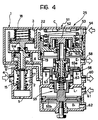
- connections of the openings 6, 19 and 22 can be made, for example, through a triple-control servo-distributor device of known type, such as that generally indicated 25 in Figures 2 to 4.
- the servo-diverter 1 can conveniently be integrated with the servo-distributor so as to form a single unit.
- the triple-control servo-distributor 25 illustrated in the drawings corresponds to the equipment produced and marketed by the Applicants under the commercial designation AC 595, and described on pages 116-118 of the instruction manual "Apparecchiature pneumatiche” published by Magneti Marelli S.p.A. in December 1983.
- the triple-control servo-distributor illustrated comprises a body 51, for example of metal, in which, from top to bottom, a series of chambers are defined:
- the servo-diverter In normal running conditions, if the braking system is not activated, the servo-diverter is in the condition illustrated in Figures 1 and 2. In this condition, the compressed air is supplied to the automatic line of the trailer through the supply connector 4 to the chamber 2 and the outlet 6 of the servo-diverter, and to the chamber B and the outlet connector 60 of the servo-distributor 25.
- the valve consisting of the movable member 9 of the servo-diverter and the obturator 15 is closed, so that the outlet 6 is disconnected from the exhaust or vent opening 5.
- the movable control member 9 of the servo-diverter As the pressure supplied to the braking system of the trailer gradually increases, the movable control member 9 of the servo-diverter is gradually displaced upwards by the effect of the pressure acting on the lower face of its piston portion 9b.
- the obturator 15 of the servo-diverter abuts the valve seat 2b formed in the body 2 around the passage through which the tubular portion 9c of the control member 9 extends with clearance. Consequently, the chamber 2 and the supply connector 4 are disconnected from the outlet 6 of the servo-diverter and from the (automatic) supply line of the trailer.
- the servo-diverter thus also limits the pressure supplied to the braking system of the trailer.
- control member 9 remains in the position illustrated in Figures 1 to 3 under the action of the spring 18, assisted by the action of the regulable pressure of the chamber E, against the action of the control pressure of the braking system coming from the chamber C of the servo-distributor.
Landscapes
- Engineering & Computer Science (AREA)
- Physics & Mathematics (AREA)
- Fluid Mechanics (AREA)
- Transportation (AREA)
- Mechanical Engineering (AREA)
- Braking Systems And Boosters (AREA)
- Valves And Accessory Devices For Braking Systems (AREA)
- Regulating Braking Force (AREA)
- Hydraulic Control Valves For Brake Systems (AREA)
Claims (3)
- Druckluft-Servoableitungsventil zur Steuerung des Bremsvorgangs eines Anhängers mit:
einem Gehäuse (1) mit
einer ersten Kammer (2) mit einem Druckversorgungsverbinder (4), einer Auslaßöffnung (6) zur Verbindung mit einer (automatischen) Versorgungsleitung des Bremssystems des Anhängers und einer Abluftöffnung (5) und einer zweiten Kammer (3) mit ersten und zweiten Einlaßöffnungen (22, 19) zur Verbindung mit einer Auslaßöffnung eines Servoverteilers des Bremssysstems eines Zugfahrzeuges bzw. mit der (regulierbaren) Steuerleitung des Bremssystems des Anhängers;
Ventilen (9c, 15, 2b) in der ersten Kammer (2) mit einem beweglichen Steuerteil (9), welches sich durch die erste und zweite Kammer (2, 3) erstreckt und zwischen entsprechenden ersten und zweiten Stellungen beweglich ist, in denen durch die Ventile (9c, 15, 2b) eine Verbindung zwischen dem Versorgungsverbinder (4) und der Auslaßöffnung (6) bzw. zwischen der Auslaßöffnung (6) und der Abluftöffnung (5) geschaffen wird, und zwar aufgrund der Wirkung der Differenz zwischen den zu der ersten und zweiten Einlaßöffnung (19, 22) der zweiten Kammer (3) zugeführten Drucke sowie gegen die entgegengesetzte Kraft federnder Einrichtungen (18),
dadurch gekennzeichnet, daß das Steuerteil (9) eine Reaktionsfläche (9b) aufweist, auf die der zu der Auslaßöffnung (6) der ersten Kammer (2) geführte Druck so einwirkt, daß das Steuerteil (9) eine Zwischenstellung einnehmen kann, in welcher die Ventile (9c, 15, 2b) die Auslaßöffnung (6) der ersten Kammer (2) von dem Versorgungsverbinder (4) und von der Abluftöffnung (5) trennen, wenn der zu der Auslaßöffnung (6) geführte Druck einen vorbestimmten Wert erreicht. - Servo-Ableitungsventil nach Anspruch 1, bei dem das bewegliche Steuerteil (9) einen Stab aufweist, der axial und abdichtend durch eine Öffnung (10) zwischen der ersten und der zweiten Kammer (2, 3) geführt werden kann,
dadurch gekennzeichnet, daß das bewegliche Steuerteil (9) einen kolbenähnlichen Abschnitt (9b) aufweist, der sich radial von dem Stab erstreckt und abdichtend und beweglich in einem Raum (2a) des Gehäuses (1) vorgesehen ist, der ständig mit der Auslaßöffnung (6) der ersten Kammer (2) verbunden ist. - Servoverteiler, insbesondere mit dreifacher Steuerung für das Bremssystem eines Zugfahrzeuges zum Ziehen eines Anhängers,
dadurch gekennzeichnet, daß es ein Servoableitungsventil gemäß einem der vorhergehenden Ansprüche aufweist.
Priority Applications (1)
| Application Number | Priority Date | Filing Date | Title |
|---|---|---|---|
| AT88830105T ATE80841T1 (de) | 1987-04-07 | 1988-03-15 | Druckluft-servoableitungsventil fuer anhaengerbremssteuerung und vorrichtung mit diesem ventil. |
Applications Claiming Priority (2)
| Application Number | Priority Date | Filing Date | Title |
|---|---|---|---|
| IT8767285A IT1215604B (it) | 1987-04-07 | 1987-04-07 | Servo deviatore pneumatico per il comando della frenatura di un veicolo rimorchiato atto a limitare lapressione alimentata all impianto frenante del veicolo rimorchiato ed apparecchiature incorporanti tale servo deviatore |
| IT6728587 | 1987-04-07 |
Publications (2)
| Publication Number | Publication Date |
|---|---|
| EP0286599A1 EP0286599A1 (de) | 1988-10-12 |
| EP0286599B1 true EP0286599B1 (de) | 1992-09-23 |
Family
ID=11301144
Family Applications (1)
| Application Number | Title | Priority Date | Filing Date |
|---|---|---|---|
| EP88830105A Expired - Lifetime EP0286599B1 (de) | 1987-04-07 | 1988-03-15 | Druckluft-Servoableitungsventil für Anhängerbremssteuerung und Vorrichtung mit diesem Ventil |
Country Status (4)
| Country | Link |
|---|---|
| EP (1) | EP0286599B1 (de) |
| AT (1) | ATE80841T1 (de) |
| DE (1) | DE3874789T2 (de) |
| IT (1) | IT1215604B (de) |
Family Cites Families (3)
| Publication number | Priority date | Publication date | Assignee | Title |
|---|---|---|---|---|
| DE2735506A1 (de) * | 1977-08-06 | 1979-02-15 | Bosch Gmbh Robert | Drosselventil |
| DE3044228C2 (de) * | 1980-11-25 | 1983-01-27 | Graubremse Gmbh, 6900 Heidelberg | Zweileitungs-Druckluftbremsanlage für Kraftfahrzeuge mit Anhänger |
| DE3413909A1 (de) * | 1984-04-13 | 1985-10-24 | Robert Bosch Gmbh, 7000 Stuttgart | Anhaenger-steuerventil fuer druckmittelbetaetigte zugwagen-bremsanlagen, insbesondere druckluftbremsanlagen |
-
1987
- 1987-04-07 IT IT8767285A patent/IT1215604B/it active
-
1988
- 1988-03-15 DE DE8888830105T patent/DE3874789T2/de not_active Expired - Fee Related
- 1988-03-15 EP EP88830105A patent/EP0286599B1/de not_active Expired - Lifetime
- 1988-03-15 AT AT88830105T patent/ATE80841T1/de not_active IP Right Cessation
Also Published As
| Publication number | Publication date |
|---|---|
| IT8767285A0 (it) | 1987-04-07 |
| DE3874789D1 (de) | 1992-10-29 |
| EP0286599A1 (de) | 1988-10-12 |
| IT1215604B (it) | 1990-02-22 |
| ATE80841T1 (de) | 1992-10-15 |
| DE3874789T2 (de) | 1993-02-25 |
Similar Documents
| Publication | Publication Date | Title |
|---|---|---|
| US4491157A (en) | Valve assembly for air bag control | |
| US4593954A (en) | Air brake valve system | |
| EP0286599B1 (de) | Druckluft-Servoableitungsventil für Anhängerbremssteuerung und Vorrichtung mit diesem Ventil | |
| US4042281A (en) | Service and emergency trailer valve | |
| US3059975A (en) | Relay emergency valve | |
| US4040673A (en) | Fluid pressure operable brake apparatus with load-compensating means for vehicles with tandem rear axles | |
| EP0221031B1 (de) | Bremsventil für Anhänger-Druckluftbremsanlage | |
| EP1270354B1 (de) | Pneumatisches Steuerventil für Bremssteuerung eines gezogenen Fahrzeuges | |
| CA1081736A (en) | Pneumatically controlled hydraulic trailer brake system | |
| EP0308375B1 (de) | Ventileinheit, insbesondere zur Verwendung im pneumatischen Bremssystem eines Zugfahrzeugs zur Steuerung der Bremsen eines Anhängers | |
| US4153143A (en) | Trailer brake actuating assembly | |
| EP0478515A1 (de) | Anhänger-Steuerventil | |
| EP0277465B1 (de) | Servosteuerventil für Druckluftbremsanlage eines Zugfahrzeuges zum Steuern der Anhängerbremsen | |
| EP1174320B1 (de) | Fahrzeugbremseinheit | |
| GB2156926A (en) | Apparatus for adjusting pressures in a dual circuit hydraulic system e g for vehicle brakes | |
| EP0239743B2 (de) | Dosier-Bremsventil mit Zweiflächen-Sekundärkolben | |
| EP0027032B1 (de) | Selbstüberlappende Ventile und Flüssigkeitsdruck-Dichtungen | |
| EP0241436B1 (de) | Druckluftventil für Bremsanlagen | |
| CA1157496A (en) | Pneumatic control valve | |
| EP0319490A2 (de) | Druckluftsteuerventil für Bremssteuerung eines Anhängers, insbesondere ein Servosteuerventil mit nachstellbarer Voreilung | |
| GB2213544A (en) | Braking corrector device for motor vehicle with hydraulic braking system and automatic levelling system with air springs | |
| SE443954B (sv) | Tryckmedelsmanovrerad bromsanleggning med automatiskt lastberoende bromskraftsreglage | |
| US3400986A (en) | Hydraulic brake control valves | |
| US3486802A (en) | Braking pressure limiting devices for automotive or other vehicles | |
| EP0322372B1 (de) | Bremsdruckregler für Kraftfahrzeuge mit Druckluftbremssystem und Federspeicherfeststellbremse |
Legal Events
| Date | Code | Title | Description |
|---|---|---|---|
| PUAI | Public reference made under article 153(3) epc to a published international application that has entered the european phase |
Free format text: ORIGINAL CODE: 0009012 |
|
| AK | Designated contracting states |
Kind code of ref document: A1 Designated state(s): AT BE CH DE ES FR GB IT LI NL SE |
|
| 17P | Request for examination filed |
Effective date: 19890331 |
|
| 17Q | First examination report despatched |
Effective date: 19901121 |
|
| RAP1 | Party data changed (applicant data changed or rights of an application transferred) |
Owner name: BENDIX HEAVY VEHICLE SYSTEMS ITALIA S.P.A. |
|
| GRAA | (expected) grant |
Free format text: ORIGINAL CODE: 0009210 |
|
| AK | Designated contracting states |
Kind code of ref document: B1 Designated state(s): AT BE CH DE ES FR GB IT LI NL SE |
|
| PG25 | Lapsed in a contracting state [announced via postgrant information from national office to epo] |
Ref country code: IT Free format text: LAPSE BECAUSE OF FAILURE TO SUBMIT A TRANSLATION OF THE DESCRIPTION OR TO PAY THE FEE WITHIN THE PRESCRIBED TIME-LIMIT;WARNING: LAPSES OF ITALIAN PATENTS WITH EFFECTIVE DATE BEFORE 2007 MAY HAVE OCCURRED AT ANY TIME BEFORE 2007. THE CORRECT EFFECTIVE DATE MAY BE DIFFERENT FROM THE ONE RECORDED. Effective date: 19920923 Ref country code: LI Effective date: 19920923 Ref country code: NL Effective date: 19920923 Ref country code: SE Effective date: 19920923 Ref country code: AT Effective date: 19920923 Ref country code: BE Effective date: 19920923 Ref country code: ES Free format text: THE PATENT HAS BEEN ANNULLED BY A DECISION OF A NATIONAL AUTHORITY Effective date: 19920923 Ref country code: CH Effective date: 19920923 |
|
| REF | Corresponds to: |
Ref document number: 80841 Country of ref document: AT Date of ref document: 19921015 Kind code of ref document: T |
|
| REF | Corresponds to: |
Ref document number: 3874789 Country of ref document: DE Date of ref document: 19921029 |
|
| ET | Fr: translation filed | ||
| REG | Reference to a national code |
Ref country code: CH Ref legal event code: PL |
|
| PG25 | Lapsed in a contracting state [announced via postgrant information from national office to epo] |
Ref country code: GB Effective date: 19930315 |
|
| NLV1 | Nl: lapsed or annulled due to failure to fulfill the requirements of art. 29p and 29m of the patents act | ||
| PLBE | No opposition filed within time limit |
Free format text: ORIGINAL CODE: 0009261 |
|
| STAA | Information on the status of an ep patent application or granted ep patent |
Free format text: STATUS: NO OPPOSITION FILED WITHIN TIME LIMIT |
|
| 26N | No opposition filed | ||
| GBPC | Gb: european patent ceased through non-payment of renewal fee |
Effective date: 19930315 |
|
| PG25 | Lapsed in a contracting state [announced via postgrant information from national office to epo] |
Ref country code: FR Effective date: 19931130 |
|
| PG25 | Lapsed in a contracting state [announced via postgrant information from national office to epo] |
Ref country code: DE Effective date: 19931201 |
|
| REG | Reference to a national code |
Ref country code: FR Ref legal event code: ST |