EP0286547B1 - Vorrichtung zum Zuführen von Wäschestücken zu einer Wäschebehandlungsmaschine - Google Patents
Vorrichtung zum Zuführen von Wäschestücken zu einer Wäschebehandlungsmaschine Download PDFInfo
- Publication number
- EP0286547B1 EP0286547B1 EP88420084A EP88420084A EP0286547B1 EP 0286547 B1 EP0286547 B1 EP 0286547B1 EP 88420084 A EP88420084 A EP 88420084A EP 88420084 A EP88420084 A EP 88420084A EP 0286547 B1 EP0286547 B1 EP 0286547B1
- Authority
- EP
- European Patent Office
- Prior art keywords
- carriages
- conveyor
- washing
- machine
- item
- Prior art date
- Legal status (The legal status is an assumption and is not a legal conclusion. Google has not performed a legal analysis and makes no representation as to the accuracy of the status listed.)
- Expired - Lifetime
Links
- 238000005406 washing Methods 0.000 claims 8
- 238000011144 upstream manufacturing Methods 0.000 abstract description 15
- 238000009434 installation Methods 0.000 abstract description 14
- 235000021183 entrée Nutrition 0.000 description 5
- 230000009471 action Effects 0.000 description 3
- 229940082150 encore Drugs 0.000 description 2
- 238000000034 method Methods 0.000 description 2
- 240000008042 Zea mays Species 0.000 description 1
- 238000007599 discharging Methods 0.000 description 1
- 238000006073 displacement reaction Methods 0.000 description 1
- 230000000694 effects Effects 0.000 description 1
- 238000010409 ironing Methods 0.000 description 1
- 230000037361 pathway Effects 0.000 description 1
- 230000008569 process Effects 0.000 description 1
- 125000006850 spacer group Chemical group 0.000 description 1
- 230000007480 spreading Effects 0.000 description 1
Images


Classifications
-
- D—TEXTILES; PAPER
- D06—TREATMENT OF TEXTILES OR THE LIKE; LAUNDERING; FLEXIBLE MATERIALS NOT OTHERWISE PROVIDED FOR
- D06F—LAUNDERING, DRYING, IRONING, PRESSING OR FOLDING TEXTILE ARTICLES
- D06F67/00—Details of ironing machines provided for in groups D06F61/00, D06F63/00, or D06F65/00
- D06F67/04—Arrangements for feeding or spreading the linen
Definitions
- the present invention relates to an installation for supplying pieces of linen for a laundry machine, for example for supplying sheets for an ironing machine.
- An installation according to the procedure of claim 1 is described in US-A-4 106 227.
- this movable beam is capable of receiving in the middle one or the other of two pairs of half-carriages which are each in the loading position, stored respectively on one of two garage tracks which are located respectively on either side of the axis of the machine and which are connected when the mobile beam is in its first axial position, on a median track fixed on this beam and able to receive one of these two pairs of half-carriages.
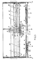
- this "feeder" for laundry items has a frame 1, elongated and transverse to the longitudinal axis 2 of the machine entry laundry, not shown, i.e. to axis 2 of the installation.
- This laundry machine is for example an ironer.
- this frame 1 supports an axial conveyor which consists of an endless belt 3 on which rests a row of independent and liftable casters 4. Plumb with the upstream end of the endless belt 3, and below it, there is a transverse bar 5 against which the sheets come to bear when they hang in front of the conveyor 3. The bar 5 overhangs a pit (not shown) which can possibly be covered to carry out the manual engagement of small pieces of laundry. Plumb with the upstream end of the conveyor 3, but above it, is fixed a fixed transverse beam 6, wider than this conveyor, which serves as a raceway for two pairs 7.8 of a half -cars, such as 9 and 10. Each half-carriage 9, 10 carries a gripper 11, 12, known per se and the operation of which will be recalled below with reference to FIG. 2.
- Two upper flanges 13, 14 of the frame 1 carry the raceways of a transverse beam 33, movable in the axial direction, which carries two carriages 42, 43, each carrying a half-rail 15a, 15b which, in position middle define a projection forming a rail portion 15 which, in the most upstream position of this beam ( Figure 1), comes into alignment with two other lateral rail portions 16, 17 to then form a continuous transverse rail 15 to 17 located axially clearly upstream of the conveyor 3.
- Each of the side portions 16, 17 carries a pair of half-carriages 18, 19, with gripping pliers similar to the pliers 11, 12 of the other pairs 7, 8, but carried by longer arms 20, all the pliers being obviously in the same horizontal plane to allow the engagement of the sheets on the conveyor 3.
- Each pair of half-carts forms a sheet loading station.
- the pairs 7 and 8 are lateral loading stations located on either side of the conveyor 3 and in alignment with the upstream part thereof.
- the pairs 18 and 19 are front loading stations, placed on either side of the axis 2 of the machine, but clearly upstream of the conveyor 3. According to the invention, as will be seen in more detail below. afterwards, the pairs 18, 19, once loaded, are in turn transferred laterally to the middle rail portion 15, and from there they are transferred to the inlet of the conveyor 3, after a halt in an intermediate position where their half -cars are symmetrically separated from each other to stretch the sheet.
- a lifting transverse bar 21, known per se, is attached to the rollers 4, and is raised and lowered with them to open the clamps in its low position, as will now be recalled with reference to FIG. 2.
- the clamp 11 is shown very roughly seen, as in Figure 1, looking at the front of the machine.
- the articulated arm 22 of this clamp In the open position, the articulated arm 22 of this clamp is engaged in a tilting pawl 23, this gripping position being indicated by dashed lines.
- the lateral engagement of a corner 24 of the sheet 25 pushes this pawl to the left, which releases the rocking arm 22.
- This arm 22 then comes to press on the corner 24 and the clamp is closed.
- the transverse bar 21 is lowered as indicated by the arrow, this bar presses on the upper boss 26 of the arm 22, which causes it to tilt and snap into 23: the clamp is then again locked in open position.
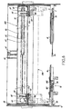
- a half-carriage 70 of the couple 7 rolls on rails 27 fixed inside the beam 6 and carries the clamp 120 identical to the clamp 12 of the half-carriage 10.
- the bar 21 is secured, by means of spacers 28 , another bar 29 which is parallel to it.
- the bar 29 moves vertically between two positions, high and low, under the action of two vertical cylinders 30, one of which at each end of the bar 29: this bar 29 is carried by the rods of the two cylinders 30 and moves between they.
- the rollers 4 are independent and they are each carried by the end of an arm 31, the other end of which is articulated around an axis 32, parallel to the bars 21 and 29 (there is therefore an arm 31 for each roller 4).
- stations 7 and 8 are associated with known devices for spacing and centering their half-carriages, which do not have have been represented here so as not to overload the drawing.
- FIGS. 3 to 6 show the different operational phases of the torque 19, while the station 18 is waiting in its garage position on the rail portion 16.
- the mobile beam referenced 33 which defines, with its carriages 42 and 43, in the middle position, the small middle rail 15, is in its most upstream position in FIG. 1, as shown in lines mixed in Figures 4 and 5.
- the rail section 15 is aligned with the two lateral sections 16 and 17, so as to form a continuous transverse rail.
- Each of the two additional stations 18 and 19 is then parked on the side, the first on the section 16 and the second on the section 17.
- the two half-carriages 181 and 182 of the station 18 for example are kept attached by means of a attachment fork 34, the two horizontal teeth of which each grip one of the half-carriages 181 and 182.
- each fork 34 is carried by a cylindrical slide 35 which is itself fixed at the end of the rod of a transverse jack 36 fixed on the section of beam, such as 37, which supports the corresponding section of rail, such as 16.
- the two slides 35 are guided in lateral translation in a common transverse tube 38 which is split on a generator to allow passage to the support of each of the two forks 34.
- the station 19 is assumed to be loaded with a sheet, which a worker has introduced through two adjacent corners between each of the two clamps which equip the station.
- the other two stations 7 and 8, for their part, are assumed to be in the course of normal tensioning operation and engagement of sheets in the machine.
- the beam 33 which is axially movable on two pathways lateral bearing 39 under the action of the two substantially axial cylinders 40 and 41, itself carries the other two carriages 42 and 43 which are able to move transversely on this beam, in a conjugate manner by approaching or deviating from it one from the other, symmetrically with respect to the axis of the machine: for this, the carriage 42 is fixed to the end of the rod of a transverse jack 44, itself fixed to the beam 33, while the carriage 43 is connected to the carriage 42 by an endless chain 45 which passes around two lateral pulleys 46, 47 returning at 150 degrees, the carriage 42 being attached at 48 to a first strand of the chain 45, while the carriage 43 is attached at 49 to the other strand of this chain.
- Each of the carriages 42 and 43 carries a longitudinal cylinder 50.51 which actuates a rocking latch 52 capable of trapping between its two legs one of the half-carriages respectively 192 and 191: in FIG. 3 are drawn in solid lines the "locked” position of the lock 52 and the "unlocked” position of this lock.
- the pair of half-carriages 19 therefore being at 39, in the middle of the rail section 15, the rod of the jacks 50, 51 is released, which locks the two latches 52 on the two half-carriages 191 and 192, then brings in the rod of the jack 40.
- the mobile beam 33 then moves towards the intermediate position 330, drawn in solid lines in FIGS. 3 and 5, the half-carriages 191 and 192 having, in this forward movement, disengaged from the teeth of the fork 34.
- the position 330 is for example located halfway between the most upstream position 331 and the most downstream position 332 which is directly above the upstream end of the conveyor 3.
- the rod of the transverse jack 44 is then brought out, which causes the spacing, symmetrical with respect to the axis of the machine, of the two carriages 42 and 43: the sheet is then stretched and centered (position drawn in phantom on the figure 6).
- This sheet is then awaiting release from the inlet of the conveyor 3, which is detected, for example, by a conventional device with a photocell, not shown in the drawing.
- the movable beam 33 is then brought back to its upstream position 331 by the action of the jacks 41 then 40, while the two half-carriages 191 and 192 are, during this transfer, brought back to their middle position by retraction of the rod of the jack 44.
- the two latches 52 are then released and the right jack 36 is activated to pull the couple 19 on its lateral garage track 17, while the couple 18, meanwhile loaded with another sheet, is in turn displaced, by the cylinder 36 on the left, towards the center of the rail 16, 15, 17, and the cycle begins again with the couple 18 while the worker loads the couple 19 with a new sheet, without prejudice to the normal operation of the two base stations 7 and 8.
- the invention is obviously not limited to the embodiment which has just been described. In particular, other locking, translation and spacing devices could be used outside its scope. It is also possible to provide a fifth station, consisting of a fifth pair of half-carriages, normally parked in the axis of the machine, but upstream of the first axial position 331. This central station would be able to advance axially towards the machine for gripping, for example by magnetic locks, on the two rail portions 15a, 15b when the movable beam 3 is in its first axial position 331, or even in its second axial position 330.
Landscapes
- Engineering & Computer Science (AREA)
- Textile Engineering (AREA)
- Branching, Merging, And Special Transfer Between Conveyors (AREA)
- Treatment Of Fiber Materials (AREA)
- Detergent Compositions (AREA)
- Accessory Of Washing/Drying Machine, Commercial Washing/Drying Machine, Other Washing/Drying Machine (AREA)
- Intermediate Stations On Conveyors (AREA)
- Control And Other Processes For Unpacking Of Materials (AREA)
- Discharge By Other Means (AREA)
Claims (4)
Priority Applications (1)
| Application Number | Priority Date | Filing Date | Title |
|---|---|---|---|
| AT88420084T ATE62942T1 (de) | 1987-03-09 | 1988-03-08 | Vorrichtung zum zufuehren von waeschestuecken zu einer waeschebehandlungsmaschine. |
Applications Claiming Priority (2)
| Application Number | Priority Date | Filing Date | Title |
|---|---|---|---|
| FR8703582A FR2612210B1 (fr) | 1987-03-09 | 1987-03-09 | Installation de fourniture de pieces de linge pour machine de blanchisserie |
| FR8703582 | 1987-03-09 |
Publications (2)
| Publication Number | Publication Date |
|---|---|
| EP0286547A1 EP0286547A1 (de) | 1988-10-12 |
| EP0286547B1 true EP0286547B1 (de) | 1991-04-24 |
Family
ID=9349016
Family Applications (1)
| Application Number | Title | Priority Date | Filing Date |
|---|---|---|---|
| EP88420084A Expired - Lifetime EP0286547B1 (de) | 1987-03-09 | 1988-03-08 | Vorrichtung zum Zuführen von Wäschestücken zu einer Wäschebehandlungsmaschine |
Country Status (6)
| Country | Link |
|---|---|
| EP (1) | EP0286547B1 (de) |
| AT (1) | ATE62942T1 (de) |
| DE (2) | DE286547T1 (de) |
| ES (1) | ES2022684B3 (de) |
| FR (1) | FR2612210B1 (de) |
| GR (1) | GR3002078T3 (de) |
Family Cites Families (4)
| Publication number | Priority date | Publication date | Assignee | Title |
|---|---|---|---|---|
| GB1169513A (en) * | 1966-01-31 | 1969-11-05 | Weir Henry J | Improvements in Laundry Feeding Machines. |
| US3729846A (en) * | 1970-05-01 | 1973-05-01 | Mc Graw Edison Co | Laundry feeding machine |
| DE2319654C3 (de) * | 1973-04-18 | 1975-09-18 | E. & E. Peters, Inh. Ludwig Mohr, 2000 Hamburg | Zuführvorrichtung für Wäschestücke od. dgl. zu einer Wäschebehandlungsmaschine |
| FR2283979A1 (fr) * | 1974-09-04 | 1976-04-02 | Bora Sa | Appareil de transfert de pieces de linge |
-
1987
- 1987-03-09 FR FR8703582A patent/FR2612210B1/fr not_active Expired
-
1988
- 1988-03-08 ES ES88420084T patent/ES2022684B3/es not_active Expired - Lifetime
- 1988-03-08 AT AT88420084T patent/ATE62942T1/de not_active IP Right Cessation
- 1988-03-08 DE DE198888420084T patent/DE286547T1/de active Pending
- 1988-03-08 DE DE8888420084T patent/DE3862499D1/de not_active Expired - Fee Related
- 1988-03-08 EP EP88420084A patent/EP0286547B1/de not_active Expired - Lifetime
-
1991
- 1991-06-06 GR GR91400749T patent/GR3002078T3/el unknown
Also Published As
| Publication number | Publication date |
|---|---|
| ATE62942T1 (de) | 1991-05-15 |
| DE3862499D1 (de) | 1991-05-29 |
| FR2612210B1 (fr) | 1989-05-26 |
| ES2022684B3 (es) | 1991-12-01 |
| FR2612210A1 (fr) | 1988-09-16 |
| GR3002078T3 (en) | 1992-12-30 |
| EP0286547A1 (de) | 1988-10-12 |
| DE286547T1 (de) | 1989-06-01 |
Similar Documents
| Publication | Publication Date | Title |
|---|---|---|
| FR1464383A (fr) | Scierie à grumes | |
| FR2553073A1 (fr) | Procede et appareil de transport de bobines enlevees d'un metier | |
| FR2499039A1 (fr) | Dispositif pour introduire des paquets de feuilles dans une machine les travaillant | |
| FR2683515A1 (fr) | Appareil pour saisir et transporter des piles d'objets plats. | |
| FR2632330A1 (fr) | Procede et dispositif d'amenee de pieces de linge a une calandre | |
| FR2574691A1 (fr) | Procede et appareil pour monter des pieces des deux cotes d'un corps principal, notamment la carrosserie d'un vehicule automobile | |
| FR2632987A1 (fr) | Procede de prehension automatisee de deux coins adjacents d'un linge plat et machine correspondante | |
| CH652954A5 (fr) | Appareil pour prelever des pieces en forme de tiges ou baguettes a partir d'une pile de telles pieces. | |
| FR2526770A1 (fr) | Dispositif pour prelever et redeposer des pieces de tissu empilees | |
| FR2584686A1 (fr) | Manipulateur de feuilles de papier applique a un appareil d'enlevement et de fourniture de feuilles de papier. | |
| CH647275A5 (fr) | Appareil automatique pour l'alimentation en meches d'une machine a filer en continu. | |
| FR2587985A1 (fr) | Transporteur de canettes pour le transport de canette d'un metier a filer a un bobinoir automatique | |
| EP0033670A1 (de) | Verfahren und Vorrichtung zum Ausformen von Weichkäse | |
| FR2556619A1 (fr) | Dispositif pour le maintien du mandrin d'un laminoir | |
| FR2494960A1 (fr) | Installation pour decouper de la viande | |
| EP0286547B1 (de) | Vorrichtung zum Zuführen von Wäschestücken zu einer Wäschebehandlungsmaschine | |
| FR2463003A1 (fr) | Perfectionnements aux machines de serigraphie concernant la monture porte-objets et son mouvement relatif par rapport a l'ecran | |
| CH403606A (fr) | Appareil pour empiler des objets | |
| FR2691480A1 (fr) | Procédé et dispositif pour introduire et extraire des bobines de fil et des bobinots sur des machines textiles. | |
| FR2605617A1 (fr) | Machine pour l'application automatique de feuilles autocollantes sur des articles | |
| FR2489802A1 (fr) | Perfectionnements a une machine rinceuse automatique, notamment pour bouteilles | |
| FR2669351A1 (fr) | Dispositif pour reunir et aligner deux a deux des blocs d'anodes pour des fours a electrolyse. | |
| EP0249568B1 (de) | Handgriff von Wickelkörpern für Zentrifugiermaschinen | |
| FR2514735A1 (fr) | Procede et installation pour le chargement de palettes avec des charges isolees differentes d'une palette a une autre | |
| FR2728852A1 (fr) | Convoyeur entrainant par intermittence des vehicules qui sont guides sur une piste de deplacement pourvue de voies ou de rails de guidage |
Legal Events
| Date | Code | Title | Description |
|---|---|---|---|
| PUAI | Public reference made under article 153(3) epc to a published international application that has entered the european phase |
Free format text: ORIGINAL CODE: 0009012 |
|
| AK | Designated contracting states |
Kind code of ref document: A1 Designated state(s): AT BE CH DE ES GB GR IT LI LU NL SE |
|
| ITCL | It: translation for ep claims filed |
Representative=s name: BARZANO' E ZANARDO MILANO S.P.A. |
|
| 17P | Request for examination filed |
Effective date: 19881203 |
|
| GBC | Gb: translation of claims filed (gb section 78(7)/1977) | ||
| TCNL | Nl: translation of patent claims filed | ||
| DET | De: translation of patent claims | ||
| 17Q | First examination report despatched |
Effective date: 19900910 |
|
| GRAA | (expected) grant |
Free format text: ORIGINAL CODE: 0009210 |
|
| AK | Designated contracting states |
Kind code of ref document: B1 Designated state(s): AT BE CH DE ES GB GR IT LI LU NL SE |
|
| REF | Corresponds to: |
Ref document number: 62942 Country of ref document: AT Date of ref document: 19910515 Kind code of ref document: T |
|
| REF | Corresponds to: |
Ref document number: 3862499 Country of ref document: DE Date of ref document: 19910529 |
|
| GBT | Gb: translation of ep patent filed (gb section 77(6)(a)/1977) | ||
| ITF | It: translation for a ep patent filed | ||
| PLBE | No opposition filed within time limit |
Free format text: ORIGINAL CODE: 0009261 |
|
| STAA | Information on the status of an ep patent application or granted ep patent |
Free format text: STATUS: NO OPPOSITION FILED WITHIN TIME LIMIT |
|
| 26N | No opposition filed | ||
| REG | Reference to a national code |
Ref country code: GR Ref legal event code: FG4A Free format text: 3002078 |
|
| EPTA | Lu: last paid annual fee | ||
| EAL | Se: european patent in force in sweden |
Ref document number: 88420084.1 |
|
| PGFP | Annual fee paid to national office [announced via postgrant information from national office to epo] |
Ref country code: GR Payment date: 19960223 Year of fee payment: 9 |
|
| PGFP | Annual fee paid to national office [announced via postgrant information from national office to epo] |
Ref country code: GB Payment date: 19960228 Year of fee payment: 9 Ref country code: BE Payment date: 19960228 Year of fee payment: 9 |
|
| PGFP | Annual fee paid to national office [announced via postgrant information from national office to epo] |
Ref country code: SE Payment date: 19960229 Year of fee payment: 9 |
|
| PGFP | Annual fee paid to national office [announced via postgrant information from national office to epo] |
Ref country code: LU Payment date: 19960301 Year of fee payment: 9 |
|
| PGFP | Annual fee paid to national office [announced via postgrant information from national office to epo] |
Ref country code: DE Payment date: 19960315 Year of fee payment: 9 Ref country code: CH Payment date: 19960315 Year of fee payment: 9 |
|
| PGFP | Annual fee paid to national office [announced via postgrant information from national office to epo] |
Ref country code: ES Payment date: 19960318 Year of fee payment: 9 |
|
| PGFP | Annual fee paid to national office [announced via postgrant information from national office to epo] |
Ref country code: AT Payment date: 19960329 Year of fee payment: 9 |
|
| PGFP | Annual fee paid to national office [announced via postgrant information from national office to epo] |
Ref country code: NL Payment date: 19960331 Year of fee payment: 9 |
|
| PG25 | Lapsed in a contracting state [announced via postgrant information from national office to epo] |
Ref country code: LU Free format text: LAPSE BECAUSE OF NON-PAYMENT OF DUE FEES Effective date: 19970308 Ref country code: GB Effective date: 19970308 Ref country code: AT Effective date: 19970308 |
|
| PG25 | Lapsed in a contracting state [announced via postgrant information from national office to epo] |
Ref country code: SE Effective date: 19970309 |
|
| PG25 | Lapsed in a contracting state [announced via postgrant information from national office to epo] |
Ref country code: ES Free format text: LAPSE BECAUSE OF NON-PAYMENT OF DUE FEES Effective date: 19970310 |
|
| PG25 | Lapsed in a contracting state [announced via postgrant information from national office to epo] |
Ref country code: LI Effective date: 19970331 Ref country code: CH Effective date: 19970331 Ref country code: BE Effective date: 19970331 |
|
| BERE | Be: lapsed |
Owner name: S.A. JEAN MICHEL Effective date: 19970331 |
|
| PG25 | Lapsed in a contracting state [announced via postgrant information from national office to epo] |
Ref country code: GR Free format text: THE PATENT HAS BEEN ANNULLED BY A DECISION OF A NATIONAL AUTHORITY Effective date: 19970930 |
|
| PG25 | Lapsed in a contracting state [announced via postgrant information from national office to epo] |
Ref country code: NL Effective date: 19971001 |
|
| GBPC | Gb: european patent ceased through non-payment of renewal fee |
Effective date: 19970308 |
|
| REG | Reference to a national code |
Ref country code: GR Ref legal event code: MM2A Free format text: 3002078 |
|
| REG | Reference to a national code |
Ref country code: CH Ref legal event code: PL |
|
| NLV4 | Nl: lapsed or anulled due to non-payment of the annual fee |
Effective date: 19971001 |
|
| PG25 | Lapsed in a contracting state [announced via postgrant information from national office to epo] |
Ref country code: DE Effective date: 19971202 |
|
| EUG | Se: european patent has lapsed |
Ref document number: 88420084.1 |
|
| REG | Reference to a national code |
Ref country code: ES Ref legal event code: FD2A Effective date: 19990301 |
|
| PG25 | Lapsed in a contracting state [announced via postgrant information from national office to epo] |
Ref country code: IT Free format text: LAPSE BECAUSE OF NON-PAYMENT OF DUE FEES;WARNING: LAPSES OF ITALIAN PATENTS WITH EFFECTIVE DATE BEFORE 2007 MAY HAVE OCCURRED AT ANY TIME BEFORE 2007. THE CORRECT EFFECTIVE DATE MAY BE DIFFERENT FROM THE ONE RECORDED. Effective date: 20050308 |