EP0286501A1 - Security device for a stoma apparatus - Google Patents
Security device for a stoma apparatus Download PDFInfo
- Publication number
- EP0286501A1 EP0286501A1 EP88400717A EP88400717A EP0286501A1 EP 0286501 A1 EP0286501 A1 EP 0286501A1 EP 88400717 A EP88400717 A EP 88400717A EP 88400717 A EP88400717 A EP 88400717A EP 0286501 A1 EP0286501 A1 EP 0286501A1
- Authority
- EP
- European Patent Office
- Prior art keywords
- end piece
- around
- tip
- locking
- face
- Prior art date
- Legal status (The legal status is an assumption and is not a legal conclusion. Google has not performed a legal analysis and makes no representation as to the accuracy of the status listed.)
- Granted
Links
Images
Classifications
-
- A—HUMAN NECESSITIES
- A61—MEDICAL OR VETERINARY SCIENCE; HYGIENE
- A61F—FILTERS IMPLANTABLE INTO BLOOD VESSELS; PROSTHESES; DEVICES PROVIDING PATENCY TO, OR PREVENTING COLLAPSING OF, TUBULAR STRUCTURES OF THE BODY, e.g. STENTS; ORTHOPAEDIC, NURSING OR CONTRACEPTIVE DEVICES; FOMENTATION; TREATMENT OR PROTECTION OF EYES OR EARS; BANDAGES, DRESSINGS OR ABSORBENT PADS; FIRST-AID KITS
- A61F5/00—Orthopaedic methods or devices for non-surgical treatment of bones or joints; Nursing devices; Anti-rape devices
- A61F5/44—Devices worn by the patient for reception of urine, faeces, catamenial or other discharge; Portable urination aids; Colostomy devices
- A61F5/445—Colostomy, ileostomy or urethrostomy devices
- A61F5/448—Means for attaching bag to seal ring
-
- A—HUMAN NECESSITIES
- A61—MEDICAL OR VETERINARY SCIENCE; HYGIENE
- A61F—FILTERS IMPLANTABLE INTO BLOOD VESSELS; PROSTHESES; DEVICES PROVIDING PATENCY TO, OR PREVENTING COLLAPSING OF, TUBULAR STRUCTURES OF THE BODY, e.g. STENTS; ORTHOPAEDIC, NURSING OR CONTRACEPTIVE DEVICES; FOMENTATION; TREATMENT OR PROTECTION OF EYES OR EARS; BANDAGES, DRESSINGS OR ABSORBENT PADS; FIRST-AID KITS
- A61F5/00—Orthopaedic methods or devices for non-surgical treatment of bones or joints; Nursing devices; Anti-rape devices
- A61F5/44—Devices worn by the patient for reception of urine, faeces, catamenial or other discharge; Portable urination aids; Colostomy devices
- A61F5/445—Colostomy, ileostomy or urethrostomy devices
- A61F2005/4486—Colostomy, ileostomy or urethrostomy devices with operable locking ring
Definitions
- the invention relates to a safety device for an ostomy fitting system.
- Ostomy devices are already known in many embodiments, that is to say devices allowing the removable attachment to the body of a user of a bag for collecting fluids and / or bodily waste. evacuated by patients who have undergone surgical procedures of the gastrointestinal tract or the urinary system, such as colostomies, ileostomies, urostomies, ureterostomies, all of these interventions being designated below by the term ostomy.
- Such devices are described, for example, in EP-A-0 171 255 or in FR-A-2 387 643, both relating to ostomy devices with a collecting bag in the form of a bag.
- the disposable or which can be emptied, and which is removably secured to a ring device fixed to the body of the user by an adhesive pad or by a belt.
- the collecting bag is put in place by a snap resulting from a push or pressure that the patient applies around the ostomy opening to make the parts of conjugate shape of the ring and of an integral part cooperate in a tight fitting from the pocket.
- Such devices are designed so that the attachment of the pocket to the ring by pressure simultaneously seals the device on the one hand and, on the other hand, prevents untimely separation of the pocket from its ring mounting.
- the known devices require that significant pressure be exerted by the patient during the assembly of the pocket and the ring. Since, however, the neighboring ostomy area is sensitive, generally painful, the application of high pressure only increases the discomfort of the user, so that known devices of the type mentioned are not fully satisfactory.
- the Applicant has set itself the goal of providing a safety device for an ostomy fitting system which is used tion less restrictive and especially less unpleasant for the patient than those of known devices, while ensuring perfect security of attachment, notwithstanding the use of a low or very low pressure for securing the pocket and the ring.
- the present invention also aims to allow the attachment of this device, which finds application regardless of the method of fixing the pad carrying the ring on the body of the user, using an adhesive product sensitive to the pressure or using a belt.
- an object of the invention to provide a device which makes it possible to modify the position slightly, easily and without risk to the patient. relative of the pocket and the ring, even when said pocket is partially filled with fluids or bodily waste.
- the present invention relates to a safety device for an ostomy fitting system comprising two elements, one of which is intended to be fixed around an artificial opening of the user's body using an appropriate fixing means.
- a fixing means such as a pressure-sensitive adhesive means, a belt or any other similar means, the other of which is integral with a collecting bag of collection of fluids and / or bodily waste, intended to be removably assembled to said first element by interlocking under the action of a pressure exerted during the bringing together of the two aforementioned elements
- the associated element the pad forming a skin protector of the peristomal area and around the outlet of one or more probe (s) or the like which is (are) integral therewith, comprises, around a first end piece tubular, a rotary member for locking, - relative to said first end piece -, a second end piece associated with the pocket and suitable for being immobilized relative to said first end piece when the two end pieces cooperate interlocking by means of elastically latching means deformable provided on the first end
- said first tubular end piece consists of an inner circular ring and an outer circular ring which is regularly cut by spaces in which the latching means are housed and, around which is arranged a rotary member for locking, said coaxial rings delimiting between them a groove in which is adapted to fit the second end piece associated with the pocket.
- said latching means consist of fastening hooks with elastic deformation regularly arranged from an angular point of view on the outer ring of the first end piece, and having on the opposite face of the inner ring, a spout which immobilizes the second end piece when the latter cooperates with the first end piece.
- the number of attachment hooks is 4.6, 8 or 12 depending on the diameter of the tips and / or the dimensions of the pockets.
- the second end piece projecting on its outer face, an annular rib with two cut sides which is housed in the groove of the first end piece, when the two aforementioned end pieces are fitted by erasing the projections of the attachment hooks.
- the rotary member for locking comprises on its internal face recesses regularly offset from an angular point of view, the number of which corresponds to that of the attachment hooks arranged on the outer ring of the first end-piece, and which allow the deformation of said hooks both for nesting and for nesting relative to one another.
- the rotary member for locking, knurled or not on its outer face has a short lever facilitating the partial rotation of said member around the first nozzle.
- a blocking block of the rotary member housed, in operating condition, in a predetermined angular opening groove provided on the inner face of the rotary locking member, which defines the stroke of the rotary locking member.
- a subject of the invention is also a bag for collecting fluids and / or bodily waste, in particular for colostomy, ileostomy, or urostomy, suitable for entering into the constitution of a device as defined above, characterized in that it comprises, around an opening which it has in one of its walls, a tip provided with an annular rib with two cut sides, which projects on the external face of said tip, and with a deformable elastic annular lip, which is located on the internal face of said nozzle, which is integral with said wall.
- the invention further relates to a skin protector suitable for entering into the constitution of such a device, characterized in that it comprises, on a pad suitable for being fixed to the body of the user using a suitable fixing means such as, in particular, a pressure-sensitive means, a belt or any other similar means, a tubular endpiece, projecting on the face of said pad opposite to that intended to come into contact with the body of the user, wearing a circular inner ring and a coaxial circular outer ring, around which is disposed a rotary locking member, said rings delimiting between them a groove in which is adapted to fit the nozzle associated with the pocket.
- a suitable fixing means such as, in particular, a pressure-sensitive means, a belt or any other similar means
- a tubular endpiece projecting on the face of said pad opposite to that intended to come into contact with the body of the user, wearing a circular inner ring and a coaxial circular outer ring, around which is disposed a rotary locking member, said rings delimiting between them a groove in which is
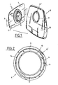
- Figures 1 to 10 relate to a safety device for ostomy fitting system according to the invention.
- This comprises an element 1, intended to be fixed around an artificial opening of the body of the user using an appropriate fixing means such as an adhesive means sensitive to pressure, known per se, and which is protected, as long as the device is not used, by a film 2 which can be easily removed by peeling (FIG. 11), or a belt 3 or any other similar means.
- an appropriate fixing means such as an adhesive means sensitive to pressure, known per se, and which is protected, as long as the device is not used, by a film 2 which can be easily removed by peeling (FIG. 11), or a belt 3 or any other similar means.
- Element 1 essentially comprises a pad 4 made of a flexible material, which can be square, rectangular, round or polygonal, for example, intended to form a skin protection of the peristomal area around which it is placed and maintained.
- This item 1 has an opening 5 concentric or substantially concentric to the stoma, and a mouthpiece 6 projecting from the face 7 of the pad 4 opposite to that carrying the adhesive material 8, FIG. 11, or when such material is not present, opposite the face in contact with the user's skin.
- the end-piece 6 is made integral with the shoe 4 by welding, for example of the thermal or high-frequency type or also by bonding by means of films compatible with the material constituting the end-piece 6.
- the pad 4 can be formed from a hydrophilic adhesive mass with a thickness between 0.5 and 3 mm, or from a very thin acrylic adhesive mass whose thickness is between a few microns and 200 microns approximately or by a combination of these two elements, that is to say, by providing around the stoma a hydrophilic adhesive gum and, at the periphery thereof, a thin acrylic adhesive mass.
- the end piece 6 can be made of polyethylene, high or low density, or of a copolymer of ethylene and vinyl acetate (EVA) or of polyvinyl chloride (PVC) or of a polyamide, by molding for example, and the films compatible for fixing the end piece to the skin protector are then advantageously films of polyethelene, PVC, polyamide, or complex barrier films or nonwovens based on polyester, polypropylene and / or polyethylene.
- EVA ethylene and vinyl acetate
- PVC polyvinyl chloride
- polyamide polyamide
- the end piece 6 comprises a circular base 9, which carries an internal circular ring 10 and an external circular ring 11 coaxial with the first and regularly cut by spaces in which are attached hooks 12, said coaxial rings delimiting between them a groove 10 ⁇ in which comes to fit the second end piece 21 associated with the pocket 20.
- the attachment hooks 12 have on the opposite face of the ring inner 10, a spout 12 ⁇ which immobilizes the second endpiece 21 secured to the pocket 20 for collecting fluids and / or bodily waste when said endpiece 21 cooperates with the endpiece 6 in the embedding condition.
- the outer circular ring 11 has on the periphery of its outer face slight bulges 14, which prevent the extraction of a rotary locking member 15 when the latter is disposed around the ring 11, the latter also comprising on its face external a stud 13 for limiting the rotation span of the rotary member 15, housed in operating condition in a groove 30 of predetermined angular opening, for example 45 °, provided on the internal face of the rotary member 15, figure 3.
- Said member is or is not knurled on its external face 13 and has a short lever 18 which facilitates the partial rotation of said member around the external circular ring 11.
- the rotary member 15 also has, on its internal face, recesses 16 regularly offset from the angular point of view, the number of which corresponds to that of the attachment hooks 12, said recesses allowing the elastic deformation of the hooks 12 when the two ends 6 and 21 are fitted and / or when one of them is extracted the other.
- the safety device for ostomy fitting system also comprises an element 19 capable of cooperating, in a removable manner, with element 1.
- This element consists essentially of the bag 20 for collecting fluids and / or body waste suitable for being evacuated through the nozzle 6 and which comprises a wall 22 ⁇ (FIG. 11), pierced with a hole 21 ⁇ through which fluids or body waste penetrate inside the pocket, which can be of the type to be discarded, or to be emptied, depending on the practice's wishes.
- a complex barrier film of the polyethylene / EVA / polyvinylidene chloride / EVA / polyethylene type such as those known under the trademark SARANEX from the company DOW CHEMICAL
- the pocket 20 is associated with the end piece 21, advantageously made of the same plastic material as the end piece 6, for example made of high density polyethylene, and securely joined to the pocket 20, on which it is welded or glued, as indicated above, so that its axis is coaxial with that of the hole 21 ⁇ .
- Said end piece 21 has a projecting annular rib 22 with two cut sides 22a, 22b projecting from its external face which is housed in the groove 10 ⁇ , elastically erasing the nozzles 12 ⁇ of the hooks 12 of the first end piece 6 when the two end pieces 6 and 21 are nested.
- the end piece 21 also comprises projecting on its internal face a deformable plastic annular lip 23 which, in known manner, ensures the sealing of the device against the fluids and / or waste collected.
- the fitting 21 is fitted into the fitting 6, making sure beforehand that the rotary member for locking 15 is arranged so that the recesses 26 are opposite.
- the hooks are elastically deformed (position in phantom in Figure 8) and enter the recesses 16, when the tip 21 is positioned at the bottom of the groove 10 ⁇ , of the endpiece 6, said hooks return to their initial position (solid line position in FIG. 8) ensuring the maintenance of the endpiece 21 in said groove 10 ⁇ by the nozzles 12 ⁇ which are then positioned against one cut sides 22b of the annular rib 22 of said end piece 21.
- Partial rotation of the rotary member 15 is then carried out for locking the pocket 20 relative to the shoe 4, this rotation being limited at the end of travel by the stop of the blocking stud 13 on one of the edges of the predetermined angular opening groove 30 provided on the internal face of the rotary member for locking 15.
- the two end pieces 6 and 21 then being fitted and locked, a rotation of the element 19 relative to element 1 is possible and the patient can take advantage of it, to slightly modify the position of the bag 20, even when the latter is partially filled, without detaching it from the pad 4.
- the base 9 of the endpiece 6 can also be provided in diametrically opposite zones with ears 31 and 32 for attaching a belt, not shown.
- Such an embodiment which also includes a pad 4 with pressure-sensitive adhesive is of particular interest for patients with an invaginated ostomy.
- the device of the invention When the device of the invention is used for urostomies or ureterostomies at least one or more catheters, probes or the like, can be fixed to the pad, as known per se, and without this resulting in structural modifications of the other parts of the device according to the invention.
Landscapes
- Health & Medical Sciences (AREA)
- Epidemiology (AREA)
- Nursing (AREA)
- Orthopedic Medicine & Surgery (AREA)
- Engineering & Computer Science (AREA)
- Biomedical Technology (AREA)
- Heart & Thoracic Surgery (AREA)
- Vascular Medicine (AREA)
- Life Sciences & Earth Sciences (AREA)
- Animal Behavior & Ethology (AREA)
- General Health & Medical Sciences (AREA)
- Public Health (AREA)
- Veterinary Medicine (AREA)
- Orthopedics, Nursing, And Contraception (AREA)
- Cookers (AREA)
Abstract
Description
L'invention a pour objet un dispositif de sécurité pour système d'appareillage des stomies.The invention relates to a safety device for an ostomy fitting system.
On connaît déjà, dans de nombreuses réalisations, des systèmes d'appareillage des stomies, c'est-à-dire des dispositifs permettant la fixation amovible au corps d'un utilisateur d'une poche de recueil de fluides et/ou de déchets corporels évacués par des patients ayant subi des interventions chirurgicales du tractus gastrointestinal ou de l'appareil urinaire, comme des colostomies, des iléostomies, des urostomies, des urétérostomies, l'ensemble de ces interventions étant désigné ci-après sous le terme d'ostomie. De tels dispositifs sont décrits, par exemple, dans EP-A-0 171 255 ou dans FR-A-2 387 643, relatifs l'un et l'autre à des dispositifs d'ostomie à poche collectrice sous forme d'un sac jetable, ou qui peut être vidé, et qui est solidarisé de manière amovible sur un dispositif de bague fixé au corps de l'utilisateur par un patin adhésif ou par une ceinture. La poche collectrice est mise en place par un encliquetage résultant d'une poussée ou pression qu'applique le patient autour de l'ouverture d'ostomie pour faire coopérer à emboîtement étanche les parties de forme conjuguée de la bague et d'une pièce solidaire de la poche. De tels dispositifs sont conçus pour que la fixation de la poche sur la bague par pression assure simultanément l'étanchéité du dispositif d'une part et, d'autre part, s'oppose à une séparation intempestive de la poche par rapport à sa bague de montage. Pour l'obtention de résultats satisfaisants, les dispositifs connus exigent qu'une pression importante soit exercée par le patient lors de l'assemblage de la poche et de la bague. Etant donné, cependant, que la zone voisine d'ostomie est sensible, généralement douloureuse, l'application d'une forte pression ne fait qu'accroître le malaise de l'utilisateur, de sorte que les dispositifs connus du type mentionné ne sont pas entièrement satisfaisants.Ostomy devices are already known in many embodiments, that is to say devices allowing the removable attachment to the body of a user of a bag for collecting fluids and / or bodily waste. evacuated by patients who have undergone surgical procedures of the gastrointestinal tract or the urinary system, such as colostomies, ileostomies, urostomies, ureterostomies, all of these interventions being designated below by the term ostomy. Such devices are described, for example, in EP-A-0 171 255 or in FR-A-2 387 643, both relating to ostomy devices with a collecting bag in the form of a bag. disposable, or which can be emptied, and which is removably secured to a ring device fixed to the body of the user by an adhesive pad or by a belt. The collecting bag is put in place by a snap resulting from a push or pressure that the patient applies around the ostomy opening to make the parts of conjugate shape of the ring and of an integral part cooperate in a tight fitting from the pocket. Such devices are designed so that the attachment of the pocket to the ring by pressure simultaneously seals the device on the one hand and, on the other hand, prevents untimely separation of the pocket from its ring mounting. In order to obtain satisfactory results, the known devices require that significant pressure be exerted by the patient during the assembly of the pocket and the ring. Since, however, the neighboring ostomy area is sensitive, generally painful, the application of high pressure only increases the discomfort of the user, so that known devices of the type mentioned are not fully satisfactory.
Compte tenu de cet état de la technique, la Demanderesse s'est fixé pour but de pourvoir à un dispositif de sécurité pour système d'appareillage des stomies qui soit d'utilisa tion moins contraignante et surtout moins désagréable pour le patient que celles des dispositifs connus, tout en assurant une parfaite sécurité de fixation, nonobstant l'utilisation d'une faible ou très faible pression pour la solidarisation de la poche et de la bague.In view of this state of the art, the Applicant has set itself the goal of providing a safety device for an ostomy fitting system which is used tion less restrictive and especially less unpleasant for the patient than those of known devices, while ensuring perfect security of attachment, notwithstanding the use of a low or very low pressure for securing the pocket and the ring.
La présente invention a également pour but de permettre la fixation de ce dispositif, qui trouve application quel que soit le mode de fixation du patin portant la bague sur le corps de l'utilisateur, à l'aide d'un produit adhésif sensible à la pression ou à l'aide d'une ceinture.The present invention also aims to allow the attachment of this device, which finds application regardless of the method of fixing the pad carrying the ring on the body of the user, using an adhesive product sensitive to the pressure or using a belt.
C'est, aussi, un but de l'invention de pourvoir à un tel dispositif qui soit applicable non seulement dans le cas d'ostomie abdominale mais également pour des ostomies du système urinaire dans lesquelles on met parfois en oeuvre un système semi-permanent, c'est-à-dire un systéme dans lequel la poche ou sac de recueil des urines est muni d'un moyen d'évacuation de son contenu, de sorte que le dispositif n'est pas renouvelé à chaque miction mais est conservé par l'utilisateur pendant une durée plus longue que les dispositifs à usage unique.It is also an object of the invention to provide such a device which is applicable not only in the case of abdominal ostomy but also for ostomies of the urinary system in which a semi-permanent system is sometimes used. , that is to say a system in which the urine collection bag or bag is provided with a means of evacuating its contents, so that the device is not renewed with each urination but is kept by the user for a longer period of time than single-use devices.
C'est, alors, dans un tel cas d'utilisation, mais aussi pour un dispositif d'ostomie abdominale, un but de l'invention de fournir un dispositif qui permet de modifier légèrement, facilement et sans risque pour le patient, la position relative de la poche et de la bague, même lorsque ladite poche est partiellement remplie de fluides ou de déchets corporels.It is, then, in such a use case, but also for an abdominal ostomy device, an object of the invention to provide a device which makes it possible to modify the position slightly, easily and without risk to the patient. relative of the pocket and the ring, even when said pocket is partially filled with fluids or bodily waste.
La présente invention a pour objet un dispositif de sécurité pour système d'appareillage des stomies comportant deux éléments dont un est prévu pour être fixé autour d'une ouverture artificielle du corps de l'utilisateur à l'aide d'un moyen de fixation approprié tel qu'un moyen adhésif sensible à la pression, une ceinture ou tout autre moyen analogue, et dont l'autre est solidaire d'une poche collectrice de recueil de fluides et/ou de déchets corporels, destinée à être assemblée de manière amovible audit premier élément par emboîtement sous l'action d'une pression exercée lors du rapprochement des deux éléments susdits, lequel dispositif est caractérisé en ce que l'élément associé au patin formant un protecteur cutané de la zone péristomiale et autour du débouché d'une ou de(s) sonde(s) ou analogue(s) qui en est (sont) solidaire(s), comporte, autour d'un premier embout tubulaire, un organe rotatif pour le verrouillage, - par rapport audit premier embout -, d'un second embout associé à la poche et propre à être immobilisé par rapport audit premier embout lorsque les deux embouts coopèrent à emboîtement par des moyens d'encliquetage élastiquement déformables prévus sur le premier embout et en nombre discret.The present invention relates to a safety device for an ostomy fitting system comprising two elements, one of which is intended to be fixed around an artificial opening of the user's body using an appropriate fixing means. such as a pressure-sensitive adhesive means, a belt or any other similar means, the other of which is integral with a collecting bag of collection of fluids and / or bodily waste, intended to be removably assembled to said first element by interlocking under the action of a pressure exerted during the bringing together of the two aforementioned elements, which device is characterized in that the associated element the pad forming a skin protector of the peristomal area and around the outlet of one or more probe (s) or the like which is (are) integral therewith, comprises, around a first end piece tubular, a rotary member for locking, - relative to said first end piece -, a second end piece associated with the pocket and suitable for being immobilized relative to said first end piece when the two end pieces cooperate interlocking by means of elastically latching means deformable provided on the first end piece and in discreet numbers.
Selon un mode de réalisation préféré de l'invention, ledit premier embout tubulaire est constitué d'une bague circulaire intérieure et d'une bague circulaire extérieure qui est régulièrement découpée par des espaces dans lesquels sont logés les moyens d'encliquetage et, autour de laquelle est disposé un organe rotatif pour le verrouillage, lesdites bagues coaxiales délimitant entre elles une gorge dans laquelle est propre à s'emboîter le second embout associé à la poche.According to a preferred embodiment of the invention, said first tubular end piece consists of an inner circular ring and an outer circular ring which is regularly cut by spaces in which the latching means are housed and, around which is arranged a rotary member for locking, said coaxial rings delimiting between them a groove in which is adapted to fit the second end piece associated with the pocket.
Selon un mode de réalisation particulièrement avantageux de l'invention, lesdits moyens d'encliquetage sont constitués par des crochets d'attache à déformation élastique régulièrement disposés du point de vue angulaire sur la bague extérieure du premier embout, et présentant sur la face en regard de la bague intérieure, un bec qui immobilise le second embout quand celui-ci coopère avec le premier embout.According to a particularly advantageous embodiment of the invention, said latching means consist of fastening hooks with elastic deformation regularly arranged from an angular point of view on the outer ring of the first end piece, and having on the opposite face of the inner ring, a spout which immobilizes the second end piece when the latter cooperates with the first end piece.
Selon une disposition avantageuse, le nombre de crochets d'attache est de 4,6, 8 ou 12 en fonction du diamètre des embouts et/ou des dimensions des poches.According to an advantageous arrangement, the number of attachment hooks is 4.6, 8 or 12 depending on the diameter of the tips and / or the dimensions of the pockets.
Selon un mode de réalisation préféré de l'inven tion, le second embout comporte en saillie sur sa face externe, une nervure annulaire à deux pans coupés qui se loge dans la gorge du premier embout, lorsque les deux embouts susdits sont emboîtés en effaçant les saillies des crochets d'attache.According to a preferred embodiment of the invention tion, the second end piece projecting on its outer face, an annular rib with two cut sides which is housed in the groove of the first end piece, when the two aforementioned end pieces are fitted by erasing the projections of the attachment hooks.
Selon un autre mode de réalisation préféré de l'invention, l'organe rotatif pour le verrouillage comprend sur sa face interne des évidements régulièrement décalés du point de vue angulaire, dont le nombre correspond à celui des crochets d'attache disposés sur la bague extérieure du premier embout, et qui autorisent la déformation desdits crochets aussi bien pour l'emboîtement que le désemboîtement l'un par rapport à l'autre.According to another preferred embodiment of the invention, the rotary member for locking comprises on its internal face recesses regularly offset from an angular point of view, the number of which corresponds to that of the attachment hooks arranged on the outer ring of the first end-piece, and which allow the deformation of said hooks both for nesting and for nesting relative to one another.
Selon un mode de réalisation avantageux de l'invention, l'organe rotatif pour le verrouillage, moleté ou non sur sa face externe, présente un court levier facilitant la rotation partielle dudit organe autour du premier embout.According to an advantageous embodiment of the invention, the rotary member for locking, knurled or not on its outer face, has a short lever facilitating the partial rotation of said member around the first nozzle.
Selon une autre caractéristique de l'invention, on prévoit sur la face externe de la bague extérieure du premier embout, un plot de blocage de l'organe rotatif, logé, en condition opératoire, dans une rainure d'ouverture angulaire prédéterminée prévue sur la face interne de l'organe rotatif pour le verrouillage, ce qui définit la course de l'organe rotatif de verrouillage.According to another characteristic of the invention, there is provided on the external face of the outer ring of the first end piece, a blocking block of the rotary member, housed, in operating condition, in a predetermined angular opening groove provided on the inner face of the rotary locking member, which defines the stroke of the rotary locking member.
L'invention a également pour objet une poche de recueil de fluides et/ou déchets corporels notamment pour colostomie, iléostomie, ou urostomie, propre à entrer dans la constitution d'un dispositif tel que défini ci-dessus, caractérisée en ce qu'elle comprend, autour d'une ouverture qu'elle présente dans une de ses parois, un embout muni d'une nervure annulaire à deux pans coupés, qui fait saillie sur la face externe dudit embout, et d'une lèvre annulaire élastique déformable, qui se trouve sur la face interne dudit embout, lequel est solidaire de ladite paroi.A subject of the invention is also a bag for collecting fluids and / or bodily waste, in particular for colostomy, ileostomy, or urostomy, suitable for entering into the constitution of a device as defined above, characterized in that it comprises, around an opening which it has in one of its walls, a tip provided with an annular rib with two cut sides, which projects on the external face of said tip, and with a deformable elastic annular lip, which is located on the internal face of said nozzle, which is integral with said wall.
L'invention a, de plus, pour objet un protecteur cutané propre à entrer dans la constitution d'un tel dispositif, caractérisé en ce qu'il comprend, sur un patin propre à être fixé au corps de l'utilisateur à l'aide d'un moyen de fixation approprié tel, notamment, qu'un moyen sensible à la pression, une ceinture ou tout autre moyen analogue, un embout tubulaire, en saillie sur la face dudit patin opposée à celle destinée à venir au contact du corps de l'utilisateur, portant une bague intérieure circulaire et une bague extérieure circulaire coaxiales, autour de laquelle est disposé un organe rotatif de verrouillage, lesdites bagues délimitant entre elles une gorge dans laquelle est propre à s'emboîter l'embout associé à la poche.The invention further relates to a skin protector suitable for entering into the constitution of such a device, characterized in that it comprises, on a pad suitable for being fixed to the body of the user using a suitable fixing means such as, in particular, a pressure-sensitive means, a belt or any other similar means, a tubular endpiece, projecting on the face of said pad opposite to that intended to come into contact with the body of the user, wearing a circular inner ring and a coaxial circular outer ring, around which is disposed a rotary locking member, said rings delimiting between them a groove in which is adapted to fit the nozzle associated with the pocket.
Outre les dispositions qui précédent, l'invention comprend encore d'autres dispositions, qui ressortiront de la description qui va suivre.In addition to the preceding arrangements, the invention also comprises other arrangements which will emerge from the description which follows.
L'invention sera mieux comprise par la description qui suit, faite à titre d'exemple et en référence aux dessins annexés.The invention will be better understood from the description which follows, given by way of example and with reference to the appended drawings.
Il doit être bien entendu, toutefois, que ces dessins et les parties descriptives correspondantes, sont donnés uniquement à titre d'illustration de l'objet de l'invention, dont ils ne constituent en aucune manière une limitation.
- - la figure 1 est une vue schématique, en perspective, des deux éléments constitutifs d'un dispositif selon l'invention,
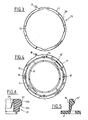
- - la figure 2 est une vue en plan de dessus, d'un embout de dispositif selon l'invention,
- - la figure 3 est une vue en plan de dessus de l'organe rotatif pour le verrouillage selon l'invention,
- - la figure 4 est une vue en plan de dessus d'un embout de dispositif selon l'invention sur lequel est disposé l'organe rotatif pour le verrouillage,
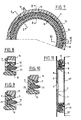
- - la figure 5 est une section d'un crochet d'attache d'un embout de dispositif selon l'invention,
- - la figure 6 est une section de l'autre embout de dispositif selon l'invention,
- - la figure 7 est une demi-vue en plan lorsque les deux embouts de dispositif selon l'invention sont dans la condition d'emboîtement,
- - la figure 8 est une section suivant la ligne 8-8 de la figure 7, à plus grande échelle,
- - la figure 9 est une section suivant la ligne 9-9 de la figure 7, à plus grande échelle,
- - la figure 10 est une section suivant la ligne 10-10 de la figure 7, à plus grande échelle,
- - la figure 11 est une vue en coupe d'un dispositif selon l'invention lorsque les deux embouts sont dans la condition d'emboîtement,
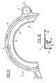
- - la figure 12 est une vue partielle, à plus grande échelle, analogue à la figure 2, mais pour une variante,
- - la figure 13 est une vue en coupe selon la ligne 13-13 de la figure 12.
- FIG. 1 is a schematic perspective view of the two constituent elements of a device according to the invention,
- FIG. 2 is a plan view from above of a device tip according to the invention,
- FIG. 3 is a top plan view of the rotary member for locking according to the invention,
- FIG. 4 is a plan view from above of a tip of a device according to the invention on which the rotary member for locking is disposed,
- FIG. 5 is a section of a hook for attaching a device tip according to the invention,
- FIG. 6 is a section of the other end piece of the device according to the invention,
- FIG. 7 is a half-plan view when the two end pieces of the device according to the invention are in the nesting condition,
- FIG. 8 is a section along line 8-8 of FIG. 7, on a larger scale,
- FIG. 9 is a section on line 9-9 of FIG. 7, on a larger scale,
- FIG. 10 is a section along line 10-10 of FIG. 7, on a larger scale,
- FIG. 11 is a sectional view of a device according to the invention when the two end pieces are in the fitting condition,
- FIG. 12 is a partial view, on a larger scale, similar to FIG. 2, but for a variant,
- - Figure 13 is a sectional view along line 13-13 of Figure 12.
Les figures 1 à 10 sont relatives à un dispositif de sécurité pour système d'appareillage des stomies selon l'invention. Celui-ci comprend un élément 1, prévu pour être fixé autour d'une ouverture artificielle du corps de l'utilisateur à l'aide d'un moyen de fixation approprié tel qu'un moyen adhésif sensible à la pression, en soi connu, et qui est protégé, aussi longtemps que le dispositif n'est pas mis en oeuvre, par une pellicule 2 qui peut être aisément retirée par pelage (figure 11), ou une ceinture 3 ou tout autre moyen analogue.Figures 1 to 10 relate to a safety device for ostomy fitting system according to the invention. This comprises an
L'élément 1 comprend essentiellement un patin 4 en un matériau souple, qui peut être de forme carrée, rectangulaire, ronde ou polygonale par exemple, destiné à former une protection cutanée de la zone péristomiale autour de laquelle il est placé et maintenu. Cet élément 1 présente une ouverture 5 concentrique ou sensiblement concentrique à la stomie, et un embout 6 en saillie sur la face 7 du patin 4 opposée à celle portant le matériau adhésif 8, figure 11, ou lorsqu'un tel matériau n'est pas présent, opposée à la face en contact avec la peau de l'utilisateur.
L'embout 6 est rendu solidaire du patin 4 par soudure, par exemple du type thermique ou haute fréquence ou encore par collage par l'intermédiaire de films compatibles avec le matériau constitutif de l'embout 6.The end-
Le patin 4 peut être constitué à partir d'une masse adhésive hydrophile d'une épaisseur comprise entre 0,5 et 3 mm, ou à partir d'une masse adhésive acrylique très mince dont l'épaisseur est comprise entre quelques microns et 200 microns environ ou encore par combinaison de ces deux éléments, c'est-à-dire, en prévoyant autour de la stomie une gomme adhésive hydrophile et, à la périphérie de celle-ci, une masse adhésive acrylique mince.The
L'embout 6 peut être réalisé en polyéthylène, haute ou basse densité, ou en copolymère d'éthylène et d'acétate de vinyle (EVA) ou en polychlorure de vinyle (PVC) ou en un polyamide, par moulage par exemple, et les films compatibles pour la fixation de l'embout sur le protecteur cutané sont alors avantageusement des films de polyéthelène, de PVC, de polyamide, ou des films barrière complexes ou des non-tissés à base de polyester, de polypropylène et/ou de polyéthylène.The
L'embout 6 comprend une embase 9 circulaire, qui porte une bague circulaire intérieure 10 et une bague circulaire extérieure 11 coaxiale à la première et régulièrement découpée par des espaces dans lesquels sont logés des crochets d'attache 12, lesdites bagues coaxiales délimitant entre elles une gorge 10ʹ dans laquelle vient s'emboîter le second embout 21 associé à la poche 20. Les crochets d'attache 12 présentent sur la face en regard de la bague intérieure 10, un bec 12ʹ qui immobilise le second embout 21 solidaire de la poche 20 de recueil des fluides et/ou des déchets corporels quand ledit embout 21 coopère avec l'embout 6 dans la condition d'embotement.The
La bague circulaire extérieure 11 présente sur le pourtour de sa face externe de légers renflements 14, qui empêchent l'extraction d'un organe rotatif de verrouillage 15 lorsque ce dernier est disposé autour de la bague 11, celle-ci comportant également sur sa face externe un plot 13 de limitation de l'envergure de rotation de l'organe rotatif 15, logé en condition opératoire dans une rainure 30 d'ouverture angulaire prédéterminée, par exemple 45°, prévue sur la face interne de l'organe rotatif 15, figure 3.The outer
Ledit organe est ou non moleté sur sa face externe 13 et présente un court levier 18 qui facilite la rotation partielle dudit organe autour de la bague circulaire extérieure 11. L'organe rotatif 15 présente également, sur sa face interne, des évidements 16 régulièrement décalés du point de vue angulaire, dont le nombre correspond à celui des crochets d'attache 12, lesdits évidements autorisant la déformation élastique des crochets 12 lorsqu'on emboîte les deux embouts 6 et 21 et/ou lorsqu'on les extraie l'un de l'autre.Said member is or is not knurled on its
Le dispositif de sécurité pour système d'appareillage des stomies selon l'invention comprend également un élément 19 propre à coopérer, de manière amovible, avec l'élément 1. Cet élément est constitué essentiellement de la poche 20 de recueil de fluides et/ou déchets corporels propres à être évacués au travers de l'embout 6 et qui comprend une paroi 22ʹ, (figure 11), percée d'un trou 21ʹ par lequel les fluides ou déchets corporels pénètrent à l'intérieur de la poche, laquelle peut être du type à jeter, ou à vider, en fonction des desiderata de la pratique. Elle peut être réalisée en un film de polyéthylène, ou de PVC, ou de polyamide (comme celui connu sous la marque déposée RILSAN) ou en un film barrière complexe du type polyéthylène/EVA/polychlorure de vinylidène/EVA/polyéthylène, comme ceux connus sous la marque déposée SARANEX de la Société DOW CHEMICAL, ou un film complexe du type EVA/copolymère polychlorure de vinylidène-EVA, comme ceux connus sous la marque CRYOVAC de la Société GRACE et sous la marque déposée SARANEX de la Société DOW CHEMICAL, ou encore en film complexe du type EVA/EVOH/EVA, ou en caoutchouc ou analogue.The safety device for ostomy fitting system according to the invention also comprises an
Conformément à l'invention, à la poche 20 est associé l'embout 21, avantageusement réalisé en la même matière plastique que l'embout 6, par exemple en polyéthylène haute densité, et solidarisé de manière étanche avec la poche 20, sur laquelle il est soudé ou collé, comme indiqué ci-dessus, de manière que son axe soit coaxial à celui du trou 21ʹ.In accordance with the invention, the
Ledit embout 21 comporte en saillie sur sa face externe une nervure annulaire 22 à deux pans coupés 22a, 22b qui se loge dans la gorge 10ʹ, en effaçant élastiquement les becs 12ʹ des crochets 12 du premier embout 6 lorsque les deux embouts 6 et 21 sont emboîtés. L'embout 21 comporte également en saillie sur sa face interne une lévre annulaire plastique déformable 23 qui, de façon en soi connue, assure l'étanchéité du dispositif à l'encontre des fluides et/ou déchets recueillis.Said
Le fait que l'embout 21 est de forme et de dimension conjuguées par rapport à l'embout 6 contribue à cette étanchéité.The fact that the
Pour la mise en place du dispositif, on réalise l'emboîtement de l'embout 21 dans l'embout 6 en s'assurant au préalable que l'organe rotatif pour le verrouillage 15 est disposé de manière que les évidements 26 se présentent en face des crochets d'attache 12. Lors de l'emboîtement, les crochets sont déformés élastiquement (position en trait mixte de la figure 8) et pénètrent dans les évidements 16, quand l'embout 21 est positionné au fond de la gorge 10ʹ, de l'embout 6, lesdits crochets reprennent leur position initiale (position en trait plein de la figure 8) en assurant le maintien de l'embout 21 dans ladite gorge 10ʹ par les becs 12ʹ qui se positionnent alors contre l'un des pans coupés 22b de la nervure annulaire 22 dudit embout 21. On procède alors à la rotation partielle de l'organe rotatif 15 pour le verrouillage de la poche 20 par rapport au patin 4, cette rotation étant limitée en fin de course par butée du plot de blocage 13 sur l'un des bords de la rainure 30 d'ouverture angulaire prédéterminée prévue sur la face interne de l'organe rotatif pour le verrouillage 15. Les deux embouts 6 et 21 étant alors emboîtés et verrouillés, une rotation de l'élément 19 par rapport à l'élément 1 est possible et le patient peut en tirer parti, pour modifier légèrement la position de la poche 20, même lorsque celle-ci est partiellement remplie, sans la désolidariser du patin 4.For the installation of the device, the fitting 21 is fitted into the
C'est un processus inverse qui est mis en oeuvre pour séparer la poche 20 du patin 4 après rotation de l'organe 15 pour deverrouiller les crochets 12.It is a reverse process which is implemented to separate the
Ainsi que cela ressort de ce qui précède, l'invention ne se limite nullement à ceux de ses modes de réalisation et d'application qui viennent d'être décrits de façon plus explicite ; elle en embrasse au contraire toutes les variantes qui peuvent venir à l'esprit du technicien en la matière, sans s'écarter du cadre, ni de la portée, de la présente invention.As is apparent from the above, the invention is in no way limited to those of its embodiments and of application which have just been described more explicitly; on the contrary, it embraces all the variants which may come to the mind of the technician in the matter, without departing from the framework, or the scope, of the present invention.
Ainsi, et comme montré sur les figures 12 et 13, l'embase 9 de l'embout 6 peut aussi être munie en des zones diamétralement opposées d'oreilles 31 et 32 d'attache d'une ceinture non représentée. Une telle réalisation qui comprend également un patin 4 à adhésif sensible à la pression est d'un intérêt particulier pour les patients présentant une stomie invaginée.Thus, and as shown in FIGS. 12 and 13, the
Lorsque le dispositif de l'Invention est utilisé pour des urostomies ou des urétérostomies au moins un ou plusieurs cathéters, des sondes ou analogues, peuvent être fixés au patin, comme connu en soi, et sans que cela entraîne de modifications de structure des autres parties du dispositif selon l'invention.When the device of the invention is used for urostomies or ureterostomies at least one or more catheters, probes or the like, can be fixed to the pad, as known per se, and without this resulting in structural modifications of the other parts of the device according to the invention.
Claims (11)
Priority Applications (1)
| Application Number | Priority Date | Filing Date | Title |
|---|---|---|---|
| AT88400717T ATE89150T1 (en) | 1987-04-10 | 1988-03-24 | SAFETY DEVICE FOR AN STOMA DEVICE. |
Applications Claiming Priority (2)
| Application Number | Priority Date | Filing Date | Title |
|---|---|---|---|
| FR8705146A FR2613613B1 (en) | 1987-04-10 | 1987-04-10 | ASSEMBLY DEVICE FOR AN OSTOMY POCKET |
| FR8705146 | 1987-04-10 |
Publications (2)
| Publication Number | Publication Date |
|---|---|
| EP0286501A1 true EP0286501A1 (en) | 1988-10-12 |
| EP0286501B1 EP0286501B1 (en) | 1993-05-12 |
Family
ID=9350024
Family Applications (1)
| Application Number | Title | Priority Date | Filing Date |
|---|---|---|---|
| EP88400717A Expired - Lifetime EP0286501B1 (en) | 1987-04-10 | 1988-03-24 | Security device for a stoma apparatus |
Country Status (8)
| Country | Link |
|---|---|
| US (1) | US4929245A (en) |
| EP (1) | EP0286501B1 (en) |
| AT (1) | ATE89150T1 (en) |
| CA (1) | CA1322506C (en) |
| DE (2) | DE286501T1 (en) |
| ES (1) | ES2005532A4 (en) |
| FR (1) | FR2613613B1 (en) |
| SU (1) | SU1724004A3 (en) |
Cited By (11)
| Publication number | Priority date | Publication date | Assignee | Title |
|---|---|---|---|---|
| EP0429199A2 (en) * | 1989-11-17 | 1991-05-29 | E.R. Squibb & Sons, Inc. | Ostomy coupling |
| US5041102A (en) * | 1989-02-03 | 1991-08-20 | E. R. Squibb & Sons, Inc. | Ostomy coupling |
| GB2219507B (en) * | 1988-06-13 | 1992-05-20 | Squibb & Sons Inc | An ostomy bag coupling |
| WO1994018919A1 (en) * | 1993-02-22 | 1994-09-01 | Coloplast A/S | An ostomy coupling |
| EP0373782B1 (en) * | 1988-12-13 | 1994-10-05 | E.R. Squibb & Sons, Inc. | Ostomy Coupling |
| EP0650709A1 (en) * | 1993-10-28 | 1995-05-03 | E.R. Squibb & Sons, Inc. | Ostomy coupling |
| EP0650710A1 (en) * | 1993-10-28 | 1995-05-03 | E.R. Squibb & Sons, Inc. | Male incontinence device |
| EP0737456A2 (en) * | 1995-04-13 | 1996-10-16 | Bristol-Myers Squibb Company | Ostomy coupling |
| EP0737460A2 (en) * | 1995-04-13 | 1996-10-16 | Bristol-Myers Squibb Company | Ostomy coupling |
| EP0830855A1 (en) * | 1996-08-20 | 1998-03-25 | Bristol-Myers Squibb Company | An ostomy coupling |
| US10076438B2 (en) | 2011-09-14 | 2018-09-18 | Coloplast A/S | Human waste collection bag |
Families Citing this family (20)
| Publication number | Priority date | Publication date | Assignee | Title |
|---|---|---|---|---|
| US5178614A (en) * | 1991-08-29 | 1993-01-12 | Mcdowell Charles E | Protective shield for a stoma pough |
| DE69328427T2 (en) * | 1992-05-12 | 2000-11-23 | Squibb & Sons Inc | METHOD FOR MOLDING PLASTIC ITEMS AND ITEMS PRODUCED THEREOF |
| US8142406B2 (en) | 2005-12-07 | 2012-03-27 | Convatec Technologies Inc. | Ostomy coupling |
| CA2688499A1 (en) * | 2007-06-01 | 2008-12-04 | Unomedical A/S | Urine measurement vessel and hose connection |
| RU2529475C2 (en) * | 2009-08-04 | 2014-09-27 | Колопласт А/С | Two-component stoma care device with auxiliary guide |
| US8316985B2 (en) * | 2009-12-23 | 2012-11-27 | Mark Bain | Methods and devices for sound abatement of an abdominal stoma |
| EP2531152B1 (en) * | 2010-02-01 | 2015-04-08 | Coloplast A/S | Ostomy appliance comprising a wicking layer |
| US9044340B2 (en) * | 2010-04-29 | 2015-06-02 | Coloplast A/S | Customizable collection device |
| CN102917673B (en) * | 2010-06-04 | 2015-06-17 | 科洛普拉斯特公司 | Filter with an extension element |
| WO2013004235A1 (en) * | 2011-07-01 | 2013-01-10 | Coloplast A/S | A coupling for an ostomy appliance |
| CN104168861B (en) * | 2012-03-06 | 2016-06-22 | 科洛普拉斯特公司 | There is the locking ring of lever arm |
| US10238529B2 (en) | 2013-09-26 | 2019-03-26 | 3 West C. LLC | Ostomy bag |
| US9993364B2 (en) | 2013-09-26 | 2018-06-12 | 3 West C, Llc | Ostomy bag |
| WO2016025314A2 (en) * | 2014-08-11 | 2016-02-18 | Western Connecticut Health Network, Inc. | Systems and methods wound drainage management |
| DK178391B1 (en) * | 2015-03-18 | 2016-10-17 | Multi-Lock Aps | An ostomy appliance |
| BR112018007234A2 (en) * | 2015-10-20 | 2018-10-16 | Coloplast A/S | ostomy appliance, sealing wafer, parts kit, and uses of a parts kit and an ostomy device |
| CN106420146B (en) * | 2016-08-19 | 2018-09-04 | 丽水市人民医院 | A kind of rotatable ostomy bag and its application method |
| US9919133B1 (en) | 2016-12-28 | 2018-03-20 | Abdullatif E. A. H. Al-Terki | Surgical drain anchoring device |
| US11298257B2 (en) * | 2017-03-22 | 2022-04-12 | 3 West C, Llc. | Ostomy apparatuses and related methods |
| CN107638244A (en) * | 2017-10-10 | 2018-01-30 | 华中科技大学同济医学院附属协和医院 | A kind of two-piece type fistula-building device |
Citations (5)
| Publication number | Priority date | Publication date | Assignee | Title |
|---|---|---|---|---|
| US2973759A (en) * | 1956-11-16 | 1961-03-07 | Jr Mis William S Plymale | Colostomy unit |
| FR2387643A1 (en) * | 1977-04-18 | 1978-11-17 | Squibb & Sons Inc | OSTOMY DEVICE |
| EP0089138A2 (en) * | 1982-03-11 | 1983-09-21 | Craig Medical Products Limited | A coupling for an ostomy bag |
| EP0163979A1 (en) * | 1984-05-09 | 1985-12-11 | Gerald Dr. Hauer | Anus-praeter supply system |
| EP0171255A2 (en) * | 1984-08-08 | 1986-02-12 | Craig Medical Products Limited | Ostomy appliance |
Family Cites Families (7)
| Publication number | Priority date | Publication date | Assignee | Title |
|---|---|---|---|---|
| US3736934A (en) * | 1971-09-21 | 1973-06-05 | A Hennessy | Surgical drainage appliance |
| NZ186585A (en) * | 1977-03-30 | 1981-03-16 | Kingsdown Medical Consultants | Coupling for joining pad or dressing to an ostomy bag |
| GB1568860A (en) * | 1978-03-21 | 1980-06-04 | Kingsdown Medical Consultants | Coupling for an ostomy bag |
| GB8403237D0 (en) * | 1984-02-07 | 1984-03-14 | Edwards J V | Ostomy appliance |
| US4610676A (en) * | 1984-05-17 | 1986-09-09 | Hollister Incorporated | Ostomy appliance coupling ring construction |
| AU601194B2 (en) * | 1986-07-31 | 1990-09-06 | E.R. Squibb & Sons, Inc. | Ostomy coupling |
| GB8618693D0 (en) * | 1986-07-31 | 1986-09-10 | Craig Med Prod Ltd | Ostomy coupling |
-
1987
- 1987-04-10 FR FR8705146A patent/FR2613613B1/en not_active Expired - Fee Related
-
1988
- 1988-03-24 AT AT88400717T patent/ATE89150T1/en not_active IP Right Cessation
- 1988-03-24 EP EP88400717A patent/EP0286501B1/en not_active Expired - Lifetime
- 1988-03-24 ES ES88400717T patent/ES2005532A4/en active Pending
- 1988-03-24 DE DE198888400717T patent/DE286501T1/en active Pending
- 1988-03-24 DE DE8888400717T patent/DE3880875T2/en not_active Expired - Fee Related
- 1988-04-08 CA CA000563716A patent/CA1322506C/en not_active Expired - Fee Related
- 1988-04-08 US US07/179,629 patent/US4929245A/en not_active Expired - Lifetime
- 1988-04-09 SU SU884355538A patent/SU1724004A3/en active
Patent Citations (5)
| Publication number | Priority date | Publication date | Assignee | Title |
|---|---|---|---|---|
| US2973759A (en) * | 1956-11-16 | 1961-03-07 | Jr Mis William S Plymale | Colostomy unit |
| FR2387643A1 (en) * | 1977-04-18 | 1978-11-17 | Squibb & Sons Inc | OSTOMY DEVICE |
| EP0089138A2 (en) * | 1982-03-11 | 1983-09-21 | Craig Medical Products Limited | A coupling for an ostomy bag |
| EP0163979A1 (en) * | 1984-05-09 | 1985-12-11 | Gerald Dr. Hauer | Anus-praeter supply system |
| EP0171255A2 (en) * | 1984-08-08 | 1986-02-12 | Craig Medical Products Limited | Ostomy appliance |
Cited By (18)
| Publication number | Priority date | Publication date | Assignee | Title |
|---|---|---|---|---|
| GB2219507B (en) * | 1988-06-13 | 1992-05-20 | Squibb & Sons Inc | An ostomy bag coupling |
| EP0373782B1 (en) * | 1988-12-13 | 1994-10-05 | E.R. Squibb & Sons, Inc. | Ostomy Coupling |
| US5041102A (en) * | 1989-02-03 | 1991-08-20 | E. R. Squibb & Sons, Inc. | Ostomy coupling |
| EP0429199A3 (en) * | 1989-11-17 | 1992-05-13 | E.R. Squibb & Sons, Inc. | Ostomy coupling |
| EP0429199A2 (en) * | 1989-11-17 | 1991-05-29 | E.R. Squibb & Sons, Inc. | Ostomy coupling |
| US5496297A (en) * | 1993-02-22 | 1996-03-05 | Coloplast A/S | Ostomy coupling |
| WO1994018919A1 (en) * | 1993-02-22 | 1994-09-01 | Coloplast A/S | An ostomy coupling |
| AU674060B2 (en) * | 1993-02-22 | 1996-12-05 | Coloplast A/S | An ostomy coupling |
| EP0650709A1 (en) * | 1993-10-28 | 1995-05-03 | E.R. Squibb & Sons, Inc. | Ostomy coupling |
| EP0650710A1 (en) * | 1993-10-28 | 1995-05-03 | E.R. Squibb & Sons, Inc. | Male incontinence device |
| AU685511B2 (en) * | 1993-10-28 | 1998-01-22 | Convatec Technologies Inc. | Male incontinence device |
| EP0737456A2 (en) * | 1995-04-13 | 1996-10-16 | Bristol-Myers Squibb Company | Ostomy coupling |
| EP0737460A2 (en) * | 1995-04-13 | 1996-10-16 | Bristol-Myers Squibb Company | Ostomy coupling |
| EP0737456A3 (en) * | 1995-04-13 | 1996-11-27 | Bristol Myers Squibb Co | |
| EP0737460A3 (en) * | 1995-04-13 | 1996-11-27 | Bristol Myers Squibb Co | |
| EP1407731A3 (en) * | 1995-04-13 | 2004-04-28 | Bristol-Myers Squibb Company | Ostomy coupling |
| EP0830855A1 (en) * | 1996-08-20 | 1998-03-25 | Bristol-Myers Squibb Company | An ostomy coupling |
| US10076438B2 (en) | 2011-09-14 | 2018-09-18 | Coloplast A/S | Human waste collection bag |
Also Published As
| Publication number | Publication date |
|---|---|
| EP0286501B1 (en) | 1993-05-12 |
| DE3880875T2 (en) | 1993-08-26 |
| FR2613613A1 (en) | 1988-10-14 |
| ES2005532A4 (en) | 1989-03-16 |
| SU1724004A3 (en) | 1992-03-30 |
| ATE89150T1 (en) | 1993-05-15 |
| US4929245A (en) | 1990-05-29 |
| FR2613613B1 (en) | 1990-12-07 |
| DE3880875D1 (en) | 1993-06-17 |
| DE286501T1 (en) | 1989-03-30 |
| CA1322506C (en) | 1993-09-28 |
Similar Documents
| Publication | Publication Date | Title |
|---|---|---|
| EP0286501B1 (en) | Security device for a stoma apparatus | |
| EP0270400B1 (en) | Ostomey device | |
| EP1663084B1 (en) | Connecting ostomy device | |
| EP0433102B1 (en) | Ostomy coupling | |
| EP0369923B1 (en) | Closure device for controlling ileo colostomies | |
| FR2626464A1 (en) | MEDICO-SURGICAL RECOVERY POCKET DEVICE | |
| EP0653196B1 (en) | Venting and internal pressure control device for ostomy pouch | |
| EP3248624B1 (en) | Device for monitoring a blood flow occurring in a haemorrhagic region | |
| FR2474858A1 (en) | DRAINING DEVICE WITH TAP FOR UROSTOMY POCKET | |
| CH620357A5 (en) | ||
| FR2523434A1 (en) | Ostomy accessory and plasterboard attachment for this accessory | |
| FR2523436A1 (en) | COLLECTION POCKET FOR OSTOMY | |
| FR2579097A1 (en) | OUTDOOR CATHETER ASSEMBLY AND APPLICATOR, AND METHOD FOR APPLYING SUCH CATHETER TO PENIS OF PATIENT | |
| FR2638634A1 (en) | ||
| EP0149391B1 (en) | Urine outlet for ureterostomy | |
| FR2809015A1 (en) | Needle holder used in hypodermic syringe, comprises sleeve whose movable tab is engaged with recess when tab is in inwardly squeezed state and disengaged when tab is extended | |
| FR2662934A1 (en) | Ostomy equipment | |
| EP0941724B1 (en) | Stoma apparatus | |
| FR2638633A1 (en) | MEDICO-SURGICAL DEVICE WITH COLLECTOR POCKET | |
| FR2548014A1 (en) | POCKET FOR STOMISE | |
| FR2721204A1 (en) | Convex rig for an invaginated stomy, e.g. colostomy | |
| FR2746633A1 (en) | APPARATUS CONNECTION FOR STOMY AND APPARATUS FOR STOMY COMPRISING SUCH A CONNECTION | |
| EP0461007A1 (en) | Stoma apparatus | |
| FR2690333A1 (en) | Body attachment location for colostomy bag - comprises rigid securing ring attachable around body opening, with deformable locking clip securing collar of bag aperture in fastening groove | |
| FR2816202A1 (en) | Positioning implement for colostomy bags has tube fitting around stoma opening and connected to emission collector |
Legal Events
| Date | Code | Title | Description |
|---|---|---|---|
| PUAI | Public reference made under article 153(3) epc to a published international application that has entered the european phase |
Free format text: ORIGINAL CODE: 0009012 |
|
| AK | Designated contracting states |
Kind code of ref document: A1 Designated state(s): AT BE CH DE ES GB IT LI NL SE |
|
| ITCL | It: translation for ep claims filed |
Representative=s name: STUDIO ASSOC. MARIETTI & PIPPARELLI |
|
| TCNL | Nl: translation of patent claims filed | ||
| GBC | Gb: translation of claims filed (gb section 78(7)/1977) | ||
| TCAT | At: translation of patent claims filed | ||
| DET | De: translation of patent claims | ||
| 17P | Request for examination filed |
Effective date: 19890223 |
|
| 17Q | First examination report despatched |
Effective date: 19901001 |
|
| GRAA | (expected) grant |
Free format text: ORIGINAL CODE: 0009210 |
|
| AK | Designated contracting states |
Kind code of ref document: B1 Designated state(s): AT BE CH DE ES GB IT LI NL SE |
|
| PG25 | Lapsed in a contracting state [announced via postgrant information from national office to epo] |
Ref country code: IT Free format text: LAPSE BECAUSE OF FAILURE TO SUBMIT A TRANSLATION OF THE DESCRIPTION OR TO PAY THE FEE WITHIN THE PRESCRIBED TIME-LIMIT;WARNING: LAPSES OF ITALIAN PATENTS WITH EFFECTIVE DATE BEFORE 2007 MAY HAVE OCCURRED AT ANY TIME BEFORE 2007. THE CORRECT EFFECTIVE DATE MAY BE DIFFERENT FROM THE ONE RECORDED. Effective date: 19930512 Ref country code: SE Effective date: 19930512 |
|
| REF | Corresponds to: |
Ref document number: 89150 Country of ref document: AT Date of ref document: 19930515 Kind code of ref document: T |
|
| GBT | Gb: translation of ep patent filed (gb section 77(6)(a)/1977) |
Effective date: 19930519 |
|
| REF | Corresponds to: |
Ref document number: 3880875 Country of ref document: DE Date of ref document: 19930617 |
|
| PG25 | Lapsed in a contracting state [announced via postgrant information from national office to epo] |
Ref country code: ES Free format text: LAPSE BECAUSE OF FAILURE TO SUBMIT A TRANSLATION OF THE DESCRIPTION OR TO PAY THE FEE WITHIN THE PRESCRIBED TIME-LIMIT Effective date: 19930823 |
|
| RAP2 | Party data changed (patent owner data changed or rights of a patent transferred) |
Owner name: LABORATOIRES MERCK-CLEVENOT |
|
| REG | Reference to a national code |
Ref country code: CH Ref legal event code: PUE Owner name: LABORATOIRES MERCK-CLEVENOT |
|
| REG | Reference to a national code |
Ref country code: GB Ref legal event code: 732E |
|
| NLS | Nl: assignments of ep-patents |
Owner name: LABORATOIRES MERCK CLEVENOT TE NOGENT-SUR-MARNE, F |
|
| BECA | Be: change of holder's address |
Free format text: 930512 LABORATOIRES *MERCK CLEVENOT:5 a 9 RUE ANQUETIL, F-94736 NOGENT-SUR-MARNE |
|
| BECH | Be: change of holder |
Free format text: 930512 LABORATOIRES *MERCK CLEVENOT |
|
| PLBI | Opposition filed |
Free format text: ORIGINAL CODE: 0009260 |
|
| 26 | Opposition filed |
Opponent name: E.R. SQIBB & SONS, INC. Effective date: 19940210 |
|
| NLR1 | Nl: opposition has been filed with the epo |
Opponent name: SQUIBB & SONS, INC. |
|
| RAP2 | Party data changed (patent owner data changed or rights of a patent transferred) |
Owner name: B. BRAUN BIOTROL |
|
| NLT2 | Nl: modifications (of names), taken from the european patent patent bulletin |
Owner name: B. BRAUN BIOTROL |
|
| PLBM | Termination of opposition procedure: date of legal effect published |
Free format text: ORIGINAL CODE: 0009276 |
|
| STAA | Information on the status of an ep patent application or granted ep patent |
Free format text: STATUS: OPPOSITION PROCEDURE CLOSED |
|
| 27C | Opposition proceedings terminated |
Effective date: 19951112 |
|
| REG | Reference to a national code |
Ref country code: CH Ref legal event code: PUE Owner name: LABORATOIRES MERCK-CLEVENOT TRANSFER- B. BRAUN BIO |
|
| NLR2 | Nl: decision of opposition | ||
| REG | Reference to a national code |
Ref country code: GB Ref legal event code: IF02 |
|
| PGFP | Annual fee paid to national office [announced via postgrant information from national office to epo] |
Ref country code: CH Payment date: 20030218 Year of fee payment: 16 |
|
| PGFP | Annual fee paid to national office [announced via postgrant information from national office to epo] |
Ref country code: GB Payment date: 20030226 Year of fee payment: 16 |
|
| PGFP | Annual fee paid to national office [announced via postgrant information from national office to epo] |
Ref country code: NL Payment date: 20030228 Year of fee payment: 16 |
|
| PGFP | Annual fee paid to national office [announced via postgrant information from national office to epo] |
Ref country code: AT Payment date: 20030304 Year of fee payment: 16 |
|
| PGFP | Annual fee paid to national office [announced via postgrant information from national office to epo] |
Ref country code: BE Payment date: 20030310 Year of fee payment: 16 |
|
| PGFP | Annual fee paid to national office [announced via postgrant information from national office to epo] |
Ref country code: DE Payment date: 20030311 Year of fee payment: 16 |
|
| PG25 | Lapsed in a contracting state [announced via postgrant information from national office to epo] |
Ref country code: AT Free format text: LAPSE BECAUSE OF NON-PAYMENT OF DUE FEES Effective date: 20040324 Ref country code: GB Free format text: LAPSE BECAUSE OF NON-PAYMENT OF DUE FEES Effective date: 20040324 |
|
| PG25 | Lapsed in a contracting state [announced via postgrant information from national office to epo] |
Ref country code: CH Free format text: LAPSE BECAUSE OF NON-PAYMENT OF DUE FEES Effective date: 20040331 Ref country code: BE Free format text: LAPSE BECAUSE OF NON-PAYMENT OF DUE FEES Effective date: 20040331 Ref country code: LI Free format text: LAPSE BECAUSE OF NON-PAYMENT OF DUE FEES Effective date: 20040331 |
|
| BERE | Be: lapsed |
Owner name: LABORATOIRES *MERCK CLEVENOT Effective date: 20040331 |
|
| PG25 | Lapsed in a contracting state [announced via postgrant information from national office to epo] |
Ref country code: NL Free format text: LAPSE BECAUSE OF NON-PAYMENT OF DUE FEES Effective date: 20041001 Ref country code: DE Free format text: LAPSE BECAUSE OF NON-PAYMENT OF DUE FEES Effective date: 20041001 |
|
| REG | Reference to a national code |
Ref country code: CH Ref legal event code: PL |
|
| GBPC | Gb: european patent ceased through non-payment of renewal fee |
Effective date: 20040324 |
|
| NLV4 | Nl: lapsed or anulled due to non-payment of the annual fee |
Effective date: 20041001 |