EP0286373A2 - Ring zur Sicherung des Bohrmeissels bei der Bergung von Bohrgestängeteilen - Google Patents
Ring zur Sicherung des Bohrmeissels bei der Bergung von Bohrgestängeteilen Download PDFInfo
- Publication number
- EP0286373A2 EP0286373A2 EP88303050A EP88303050A EP0286373A2 EP 0286373 A2 EP0286373 A2 EP 0286373A2 EP 88303050 A EP88303050 A EP 88303050A EP 88303050 A EP88303050 A EP 88303050A EP 0286373 A2 EP0286373 A2 EP 0286373A2
- Authority
- EP
- European Patent Office
- Prior art keywords
- bit
- hammer
- retaining ring
- ring
- drill bit
- Prior art date
- Legal status (The legal status is an assumption and is not a legal conclusion. Google has not performed a legal analysis and makes no representation as to the accuracy of the status listed.)
- Withdrawn
Links
- 238000009527 percussion Methods 0.000 claims abstract description 10
- 239000013013 elastic material Substances 0.000 claims description 3
- 230000008878 coupling Effects 0.000 claims 1
- 238000010168 coupling process Methods 0.000 claims 1
- 238000005859 coupling reaction Methods 0.000 claims 1
- 230000033001 locomotion Effects 0.000 abstract description 2
- 238000005553 drilling Methods 0.000 description 11
- 239000004677 Nylon Substances 0.000 description 4
- 229920001778 nylon Polymers 0.000 description 4
- 238000011084 recovery Methods 0.000 description 3
- 229910000831 Steel Inorganic materials 0.000 description 2
- 230000006378 damage Effects 0.000 description 2
- 239000000463 material Substances 0.000 description 2
- 239000011435 rock Substances 0.000 description 2
- 239000003381 stabilizer Substances 0.000 description 2
- 239000010959 steel Substances 0.000 description 2
- 208000027418 Wounds and injury Diseases 0.000 description 1
- 230000015572 biosynthetic process Effects 0.000 description 1
- -1 earth Substances 0.000 description 1
- 208000014674 injury Diseases 0.000 description 1
- 239000002184 metal Substances 0.000 description 1
- 238000000034 method Methods 0.000 description 1
- 230000002028 premature Effects 0.000 description 1
- 238000010008 shearing Methods 0.000 description 1
- 239000011800 void material Substances 0.000 description 1
- 239000002699 waste material Substances 0.000 description 1
Images
Classifications
-
- E—FIXED CONSTRUCTIONS
- E21—EARTH OR ROCK DRILLING; MINING
- E21B—EARTH OR ROCK DRILLING; OBTAINING OIL, GAS, WATER, SOLUBLE OR MELTABLE MATERIALS OR A SLURRY OF MINERALS FROM WELLS
- E21B17/00—Drilling rods or pipes; Flexible drill strings; Kellies; Drill collars; Sucker rods; Cables; Casings; Tubings
- E21B17/02—Couplings; joints
- E21B17/04—Couplings; joints between rod or the like and bit or between rod and rod or the like
- E21B17/07—Telescoping joints for varying drill string lengths; Shock absorbers
- E21B17/076—Telescoping joints for varying drill string lengths; Shock absorbers between rod or pipe and drill bit
-
- E—FIXED CONSTRUCTIONS
- E21—EARTH OR ROCK DRILLING; MINING
- E21B—EARTH OR ROCK DRILLING; OBTAINING OIL, GAS, WATER, SOLUBLE OR MELTABLE MATERIALS OR A SLURRY OF MINERALS FROM WELLS
- E21B17/00—Drilling rods or pipes; Flexible drill strings; Kellies; Drill collars; Sucker rods; Cables; Casings; Tubings
- E21B17/02—Couplings; joints
- E21B17/04—Couplings; joints between rod or the like and bit or between rod and rod or the like
- E21B17/06—Releasing-joints, e.g. safety joints
-
- E—FIXED CONSTRUCTIONS
- E21—EARTH OR ROCK DRILLING; MINING
- E21B—EARTH OR ROCK DRILLING; OBTAINING OIL, GAS, WATER, SOLUBLE OR MELTABLE MATERIALS OR A SLURRY OF MINERALS FROM WELLS
- E21B17/00—Drilling rods or pipes; Flexible drill strings; Kellies; Drill collars; Sucker rods; Cables; Casings; Tubings
- E21B17/02—Couplings; joints
- E21B17/04—Couplings; joints between rod or the like and bit or between rod and rod or the like
- E21B17/07—Telescoping joints for varying drill string lengths; Shock absorbers
-
- E—FIXED CONSTRUCTIONS
- E21—EARTH OR ROCK DRILLING; MINING
- E21B—EARTH OR ROCK DRILLING; OBTAINING OIL, GAS, WATER, SOLUBLE OR MELTABLE MATERIALS OR A SLURRY OF MINERALS FROM WELLS
- E21B4/00—Drives for drilling, used in the borehole
- E21B4/06—Down-hole impacting means, e.g. hammers
Definitions
- the instant invention relates to drilling in general and more particularly to an apparatus or a system for recovering drill string components within a hole.
- hams, stabilizers and otherwise good drill pipe are relatively expensive commodities and to leave them in the ground is simply a waste of resources. For example, a hammer costs about 7000 (Canadian) and a five foot (1.5m) drill rod costs about 440 (Canadian).
- drilling equipment components are often equipped with shear pins that are designed to break when predetermined maximum stresses are experienced by the equipment (usually rotational forces).
- the pins are designed to shear thus freeing the component in question and preventing injury to personnel and damage to related components.
- shear pins require a drilled hole to pass through and means for maintaining their position during normal (i.e., nonstressful) working situations. It is difficult to form a hole through a number of hardened drill components and maintain the alignment of the hole so as to allow the pin to bridge the various components. In addition, shear pins usually are not contemplated for equipment recovery purposes although that may be an unintended result.
- drill bits are usually attached to a percussion hammer.
- a steel bit retaining ring is disposed around the drill bit shank to maintain the drill bit within the hammer.
- the ends of the splines on the drill bit act as stops against the ring as the bit is driven by the piston in the hammer to cause reciprocating percussive movement.
- bit retaining ring having a predetermined shear strength registered with a drill bit.
- the bit retaining ring is constructed to break upon a predetermined loading so as to allow for the recovery of selected components.
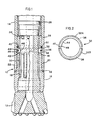
- Figure 1 depicts the distal end 10 of a drill string.
- a drill bit 12 is affixed to a percussion hammer 14 via threaded chuck 16.
- the chuck 16 is threaded 20 to mate with lower extension 22 of the hammer 14 and maintain the position of the bit 12 within the hammer 14.
- the shank 18 of the bit 12 includes a plurality of upper splines 24 that slide against support guide 26.
- the support guide 26 is secured by ring 50.
- Blow energy is imparted against the bit 12 by hammer piston 28.
- Vertical reciprocating travel of the bit 12 is limited by the upper splines 24 and a plurality of lower splines 30 meeting breakaway bit retaining ring 32.
- the ring 32 is disposed within the void 34 formed between the bottom of the support guide 26 and top of the chuck 16.
- the bit retaining ring 32 is comprised of two half circles 32A and 32B of a preferably elastic material (such as nylon) having a predetermined maximum shear strength.
- An O-ring 36 girdles the bit retaining ring 32 in groove 38 to assist in keeping the half circles 32A and 32B of the bit retaining ring 32 in place about the shank 18.
- the ring 32 has flat upper and lower surfaces 40 and 42, canted upper and lower intermediate surfaces 44 and 46 and a shank registering surface 48 essentially perpendicular to the parallel upper and lower surfaces 40 and 42.
- the canted upper intermediate surface 44 acts as a lower limit stop for the upper splines 24 and conversely the canted lower intermediate surface 46 acts as an upper limit stop for the lower splines 30.
- the drill bit 12 is inserted into the chuck 16.
- the two halves of the retaining ring 32 are placed about the shank 18 between the upper splines 24 and the lower splines 30 and held together and in place by the O-ring 36.
- the bit-shank-ring assembly is then screwed into the extension 22 of the hammer 14.
- Gasket 52 prevents dirt from entering the threads 20.
- the hammer 14 is then affixed to a drill rod and ultimately to the drilling rig in the usual manner.
- the expression "negatively applied load” means any affirmative load that ultimately tends to pull and separate the hammer away from the bit and away from the end of the hole.
- drilling an object into a medium requires a positive load; withdrawing the object requires a negative load.
- a negatively applied load would pull the components upwardly.
- a negatively applied load would be in the down position.
- the embodiment in Figure 1 is pictured in a downward direction.
- a known negatively applied load may be applied to the entire drill string.
- the negatively applied load will cause the hammer 14 to rise so that the upper splines 24 are brought into contact with the upper intermediate surface 44 of the bit retaining ring 32.
- the bit retaining ring 32 will ultimately shear, thereby freeing the hammer 14 from the bit 12.
- the hammer 14 will slide free of the bit 12.
- the rod and hammer 14 circumscribing the chuck 16 can then be removed upwardly through the hole leaving only the bit 12 entombed in the hole.
- the physical dimensions and the materials of the bit will, of necessity, be a function of the dimensions of the bit, hammer and contemplated drilling conditions.
- a nylon bit retaining ring of about 4.5 inches (11.4 cm) outside diameter was about 0.63 inches (1.6 cm) thick and about 0.5 inches (1.3 cm) high was designed to shear when subjected to a pull of about 12 tons (107 kN) vertical pull.
- a set of the rings 32 were installed on a high pressure hammer at the end of an in-the-hole drill. After having drilled 946 ough hard rock, the bit retaining ring 32 failed after drilling a breakthrough hole. As a consequence, it was determined that the bit retaining ring 32 may be designed to be somewhat thicker and stronger.
- a negatively applied pull on the drill string may be engendered by any jacking device.
- a twenty-four inch (61 cm) square base plate having a thickness of one inch (2.5 cm) and a central aperture was placed over a down hole with the rod extending through the aperture. The plate was carefully placed over the hole so as to be perpendicular to the drill string.
- a hollow hydraulic jack with a clamp for securing the rod to the jack was energized to pull up on the rod.
- a set of prototype nylon bit rings 32 successfully sheared at 20 tons (178 kN) of pull freeing the hammer 14 and associated rod.
- the breakaway bit retaining ring 32 is designed and sized with the expectation that ultimately it may have to be affirmatively sheared, the ring 32 still must be strong enough to resist premature failure resulting from the typical stresses experienced during normal drilling operations.
- the drill bit 12 and the hammer 14 are subjected to tremendous physical forces, heat, dirt, corrosive material, etc. Therefore, although the shear resistance of the breakaway bit retaining ring 32 is less than a conventional metallic ring, it still must exhibit sufficient physical resistance so that it will shear only when such a state-of-affairs is desired by the operator.
- a weak ring 32 is worthless and an extremely strong one will only duplicate the properties of the prior art rings. Rather the shear strength of the ring should be selected to be: (1) greater than the typical shear experienced by the bit ring; (2) within the shear causing capabilities of the jack; and (3) less than the shear characteristics exhibited by prior art rings.
Landscapes
- Engineering & Computer Science (AREA)
- Geology (AREA)
- Life Sciences & Earth Sciences (AREA)
- Mining & Mineral Resources (AREA)
- Physics & Mathematics (AREA)
- Environmental & Geological Engineering (AREA)
- Fluid Mechanics (AREA)
- Mechanical Engineering (AREA)
- General Life Sciences & Earth Sciences (AREA)
- Geochemistry & Mineralogy (AREA)
- Earth Drilling (AREA)
- Drilling And Boring (AREA)
- Percussive Tools And Related Accessories (AREA)
Applications Claiming Priority (2)
| Application Number | Priority Date | Filing Date | Title |
|---|---|---|---|
| CA534135 | 1987-04-08 | ||
| CA534135 | 1987-04-08 |
Publications (2)
| Publication Number | Publication Date |
|---|---|
| EP0286373A2 true EP0286373A2 (de) | 1988-10-12 |
| EP0286373A3 EP0286373A3 (de) | 1989-07-12 |
Family
ID=4135391
Family Applications (1)
| Application Number | Title | Priority Date | Filing Date |
|---|---|---|---|
| EP88303050A Withdrawn EP0286373A3 (de) | 1987-04-08 | 1988-04-06 | Ring zur Sicherung des Bohrmeissels bei der Bergung von Bohrgestängeteilen |
Country Status (7)
| Country | Link |
|---|---|
| EP (1) | EP0286373A3 (de) |
| JP (1) | JPS63268895A (de) |
| AU (1) | AU1432988A (de) |
| BR (1) | BR8801655A (de) |
| FI (1) | FI881622L (de) |
| ZA (1) | ZA882413B (de) |
| ZW (1) | ZW3688A1 (de) |
Cited By (9)
| Publication number | Priority date | Publication date | Assignee | Title |
|---|---|---|---|---|
| WO1991009203A1 (en) * | 1989-12-15 | 1991-06-27 | Numa Tool Company | Downhole drill bit and bit coupling |
| US6021856A (en) * | 1998-05-29 | 2000-02-08 | Numa Tool Company | Bit retention system |
| US6070678A (en) * | 1998-05-01 | 2000-06-06 | Numa Tool Company | Bit retention system |
| GB2378196A (en) * | 2001-07-30 | 2003-02-05 | Smith International | Downhole release joint |
| GB2382090A (en) * | 2001-11-16 | 2003-05-21 | Varel International Inc | Breakable washer for an earth boring bit |
| WO2005019594A1 (en) * | 2003-08-13 | 2005-03-03 | Baker Hughes Incorporated | Releasable mill |
| US20120152521A1 (en) * | 2011-02-28 | 2012-06-21 | Akkerman Neil H | Disconnect assembly for cylindrical members |
| CN103774998A (zh) * | 2012-10-18 | 2014-05-07 | 张卫星 | 钻探用内芯可脱式钻头的内芯开启装置 |
| CN115584939A (zh) * | 2022-10-13 | 2023-01-10 | 贵州远东兄弟钻探有限公司 | 一种带有螺纹补偿功能的钻机加杆装置及其系统 |
Families Citing this family (1)
| Publication number | Priority date | Publication date | Assignee | Title |
|---|---|---|---|---|
| CA2423295C (en) * | 2000-09-22 | 2009-05-12 | Ingersoll-Rand Company | Quick release drill bit for down-hole drills |
Family Cites Families (8)
| Publication number | Priority date | Publication date | Assignee | Title |
|---|---|---|---|---|
| US3322216A (en) * | 1964-11-18 | 1967-05-30 | Ingersoll Rand Co | Anvil for percussive drill |
| US3499664A (en) * | 1968-07-29 | 1970-03-10 | Bruns Tool Co | Releasing collar |
| GB1419981A (en) * | 1973-01-09 | 1976-01-07 | Halifax Tool Co Ltd | Percussion drills |
| GB1472501A (en) * | 1975-01-13 | 1977-05-04 | Gien Abraham | Pneumatic percussive machines |
| US3945444A (en) * | 1975-04-01 | 1976-03-23 | The Anaconda Company | Split bit casing drill |
| US4445572A (en) * | 1981-08-17 | 1984-05-01 | Baker International Corporation | Unrestricted bore safety joint |
| DE3514030A1 (de) * | 1985-04-18 | 1986-10-23 | Hütte & Co. Bohrtechnik GmbH, 5960 Olpe | Bohrvorrichtung, insbesondere zum rammbohren |
| FR2595404B1 (fr) * | 1986-03-10 | 1988-07-08 | Alsthom | Raccord pour forage |
-
1988
- 1988-03-25 JP JP63071697A patent/JPS63268895A/ja active Pending
- 1988-04-06 EP EP88303050A patent/EP0286373A3/de not_active Withdrawn
- 1988-04-06 ZW ZW36/88A patent/ZW3688A1/xx unknown
- 1988-04-07 FI FI881622A patent/FI881622L/fi not_active Application Discontinuation
- 1988-04-07 ZA ZA882413A patent/ZA882413B/xx unknown
- 1988-04-07 AU AU14329/88A patent/AU1432988A/en not_active Abandoned
- 1988-04-07 BR BR8801655A patent/BR8801655A/pt unknown
Cited By (14)
| Publication number | Priority date | Publication date | Assignee | Title |
|---|---|---|---|---|
| WO1991009203A1 (en) * | 1989-12-15 | 1991-06-27 | Numa Tool Company | Downhole drill bit and bit coupling |
| AU640992B2 (en) * | 1989-12-15 | 1993-09-09 | Numa Tool Company | Downhole drill bit and bit coupling |
| US6070678A (en) * | 1998-05-01 | 2000-06-06 | Numa Tool Company | Bit retention system |
| US6021856A (en) * | 1998-05-29 | 2000-02-08 | Numa Tool Company | Bit retention system |
| US7198101B2 (en) | 2001-07-30 | 2007-04-03 | Smith International, Inc. | Downhole release joint |
| GB2378196B (en) * | 2001-07-30 | 2005-09-14 | Smith International | Downhole release joint |
| GB2378196A (en) * | 2001-07-30 | 2003-02-05 | Smith International | Downhole release joint |
| GB2382090A (en) * | 2001-11-16 | 2003-05-21 | Varel International Inc | Breakable washer for an earth boring bit |
| US6892832B2 (en) | 2001-11-16 | 2005-05-17 | Varel International, Ltd. | Breakable washer earth boring bit |
| WO2005019594A1 (en) * | 2003-08-13 | 2005-03-03 | Baker Hughes Incorporated | Releasable mill |
| US20120152521A1 (en) * | 2011-02-28 | 2012-06-21 | Akkerman Neil H | Disconnect assembly for cylindrical members |
| US9512683B2 (en) * | 2011-02-28 | 2016-12-06 | Neil H. Akkerman | Disconnect assembly for cylindrical members |
| CN103774998A (zh) * | 2012-10-18 | 2014-05-07 | 张卫星 | 钻探用内芯可脱式钻头的内芯开启装置 |
| CN115584939A (zh) * | 2022-10-13 | 2023-01-10 | 贵州远东兄弟钻探有限公司 | 一种带有螺纹补偿功能的钻机加杆装置及其系统 |
Also Published As
| Publication number | Publication date |
|---|---|
| FI881622A0 (fi) | 1988-04-07 |
| JPS63268895A (ja) | 1988-11-07 |
| BR8801655A (pt) | 1988-11-16 |
| ZA882413B (en) | 1988-09-28 |
| EP0286373A3 (de) | 1989-07-12 |
| AU1432988A (en) | 1988-10-13 |
| FI881622A7 (fi) | 1988-10-09 |
| FI881622L (fi) | 1988-10-09 |
| ZW3688A1 (en) | 1988-10-12 |
Similar Documents
| Publication | Publication Date | Title |
|---|---|---|
| US4523878A (en) | Remotely replaceable guidepost method and apparatus | |
| CN101460694B (zh) | 多段式冲击钻头组件 | |
| AU6657600A (en) | A method for improving performance of fishing and drilling jars in deviated and extended reach wellbores | |
| US5103903A (en) | Jar | |
| JPH10507796A (ja) | セントラライザー | |
| US2947362A (en) | Fishing tool | |
| US3485310A (en) | Wire line core barrel apparatus | |
| US4658901A (en) | Method of and apparatus for removing stuck well pipe | |
| CN111456664B (zh) | 一种可防止岩心卡堵的取心钻具 | |
| US3316963A (en) | Repair of wells | |
| US3108637A (en) | Packer retrieving tool | |
| JPS63268895A (ja) | ドリル刃と衝撃ハンマ、および刃保持リング | |
| US11629569B2 (en) | System and method for moving stuck objects in a well | |
| CN112049596A (zh) | 一种可退式捞矛及打捞方法 | |
| US4557339A (en) | Borehole conditioning apparatus | |
| EP0086582A1 (de) | Vorrichtung zur Entfernung von Packern aus Erdölbohrlöchern | |
| US2998067A (en) | Method and apparatus for releasing stuck drill pipe | |
| HUT63911A (en) | Method and apparatus for breaking rock and other, similar material | |
| US3920089A (en) | Removable stem for raise bit | |
| EP2029851B1 (de) | Spülwelle für das bohrgestänge einer drehschlagbohranlage, prallpaket für eine spülwelle und drehschlagbohranlage | |
| CN217897741U (zh) | 一种三翼同心跟管钻具 | |
| US6516904B1 (en) | Mining drill steels and methods of making the same | |
| US583317A (en) | Fishing-tool | |
| CN116927702A (zh) | 一种连续震击解卡器 | |
| CN1159848A (zh) | 扶正器 |
Legal Events
| Date | Code | Title | Description |
|---|---|---|---|
| PUAI | Public reference made under article 153(3) epc to a published international application that has entered the european phase |
Free format text: ORIGINAL CODE: 0009012 |
|
| AK | Designated contracting states |
Kind code of ref document: A2 Designated state(s): DE ES FR GB GR IT SE |
|
| PUAL | Search report despatched |
Free format text: ORIGINAL CODE: 0009013 |
|
| AK | Designated contracting states |
Kind code of ref document: A3 Designated state(s): DE ES FR GB GR IT SE |
|
| STAA | Information on the status of an ep patent application or granted ep patent |
Free format text: STATUS: THE APPLICATION IS DEEMED TO BE WITHDRAWN |
|
| 18D | Application deemed to be withdrawn |
Effective date: 19900115 |