EP0285416B1 - Fuel filter assembly with heater - Google Patents
Fuel filter assembly with heater Download PDFInfo
- Publication number
- EP0285416B1 EP0285416B1 EP88302884A EP88302884A EP0285416B1 EP 0285416 B1 EP0285416 B1 EP 0285416B1 EP 88302884 A EP88302884 A EP 88302884A EP 88302884 A EP88302884 A EP 88302884A EP 0285416 B1 EP0285416 B1 EP 0285416B1
- Authority
- EP
- European Patent Office
- Prior art keywords
- fuel
- filter
- filter head
- spin
- chamber
- Prior art date
- Legal status (The legal status is an assumption and is not a legal conclusion. Google has not performed a legal analysis and makes no representation as to the accuracy of the status listed.)
- Expired - Lifetime
Links
- 239000000446 fuel Substances 0.000 title claims description 106
- 239000012530 fluid Substances 0.000 claims description 30
- 238000004891 communication Methods 0.000 claims description 15
- 239000002283 diesel fuel Substances 0.000 claims description 14
- 239000002828 fuel tank Substances 0.000 claims description 12
- 239000000356 contaminant Substances 0.000 claims description 9
- 230000002093 peripheral effect Effects 0.000 claims description 9
- 238000012546 transfer Methods 0.000 description 6
- 239000002184 metal Substances 0.000 description 4
- XLYOFNOQVPJJNP-UHFFFAOYSA-N water Substances O XLYOFNOQVPJJNP-UHFFFAOYSA-N 0.000 description 4
- 238000002347 injection Methods 0.000 description 3
- 239000007924 injection Substances 0.000 description 3
- 230000000717 retained effect Effects 0.000 description 3
- 150000001875 compounds Chemical class 0.000 description 2
- 230000000994 depressogenic effect Effects 0.000 description 2
- 239000000463 material Substances 0.000 description 2
- 238000000034 method Methods 0.000 description 2
- 239000000523 sample Substances 0.000 description 2
- 238000007789 sealing Methods 0.000 description 2
- 241000272525 Anas platyrhynchos Species 0.000 description 1
- 239000000853 adhesive Substances 0.000 description 1
- 230000001070 adhesive effect Effects 0.000 description 1
- 230000004888 barrier function Effects 0.000 description 1
- 230000033228 biological regulation Effects 0.000 description 1
- 239000004020 conductor Substances 0.000 description 1
- 238000011109 contamination Methods 0.000 description 1
- 238000001914 filtration Methods 0.000 description 1
- 238000010438 heat treatment Methods 0.000 description 1
- 108010036050 human cationic antimicrobial protein 57 Proteins 0.000 description 1
- 238000003780 insertion Methods 0.000 description 1
- 230000037431 insertion Effects 0.000 description 1
- 238000012423 maintenance Methods 0.000 description 1
- 230000014759 maintenance of location Effects 0.000 description 1
- 239000013618 particulate matter Substances 0.000 description 1
- 229920000728 polyester Polymers 0.000 description 1
- 238000004382 potting Methods 0.000 description 1
- 239000004065 semiconductor Substances 0.000 description 1
- 238000013022 venting Methods 0.000 description 1
- 238000010792 warming Methods 0.000 description 1
Images


Classifications
-
- B—PERFORMING OPERATIONS; TRANSPORTING
- B01—PHYSICAL OR CHEMICAL PROCESSES OR APPARATUS IN GENERAL
- B01D—SEPARATION
- B01D21/00—Separation of suspended solid particles from liquids by sedimentation
- B01D21/24—Feed or discharge mechanisms for settling tanks
- B01D21/245—Discharge mechanisms for the sediments
- B01D21/2483—Means or provisions for manually removing the sediments
-
- B—PERFORMING OPERATIONS; TRANSPORTING
- B01—PHYSICAL OR CHEMICAL PROCESSES OR APPARATUS IN GENERAL
- B01D—SEPARATION
- B01D17/00—Separation of liquids, not provided for elsewhere, e.g. by thermal diffusion
-
- B—PERFORMING OPERATIONS; TRANSPORTING
- B01—PHYSICAL OR CHEMICAL PROCESSES OR APPARATUS IN GENERAL
- B01D—SEPARATION
- B01D17/00—Separation of liquids, not provided for elsewhere, e.g. by thermal diffusion
- B01D17/02—Separation of non-miscible liquids
- B01D17/0208—Separation of non-miscible liquids by sedimentation
- B01D17/0214—Separation of non-miscible liquids by sedimentation with removal of one of the phases
-
- B—PERFORMING OPERATIONS; TRANSPORTING
- B01—PHYSICAL OR CHEMICAL PROCESSES OR APPARATUS IN GENERAL
- B01D—SEPARATION
- B01D17/00—Separation of liquids, not provided for elsewhere, e.g. by thermal diffusion
- B01D17/02—Separation of non-miscible liquids
- B01D17/04—Breaking emulsions
- B01D17/042—Breaking emulsions by changing the temperature
-
- B—PERFORMING OPERATIONS; TRANSPORTING
- B01—PHYSICAL OR CHEMICAL PROCESSES OR APPARATUS IN GENERAL
- B01D—SEPARATION
- B01D17/00—Separation of liquids, not provided for elsewhere, e.g. by thermal diffusion
- B01D17/08—Thickening liquid suspensions by filtration
- B01D17/10—Thickening liquid suspensions by filtration with stationary filtering elements
-
- B—PERFORMING OPERATIONS; TRANSPORTING
- B01—PHYSICAL OR CHEMICAL PROCESSES OR APPARATUS IN GENERAL
- B01D—SEPARATION
- B01D17/00—Separation of liquids, not provided for elsewhere, e.g. by thermal diffusion
- B01D17/12—Auxiliary equipment particularly adapted for use with liquid-separating apparatus, e.g. control circuits
-
- B—PERFORMING OPERATIONS; TRANSPORTING
- B01—PHYSICAL OR CHEMICAL PROCESSES OR APPARATUS IN GENERAL
- B01D—SEPARATION
- B01D21/00—Separation of suspended solid particles from liquids by sedimentation
- B01D21/0003—Making of sedimentation devices, structural details thereof, e.g. prefabricated parts
-
- B—PERFORMING OPERATIONS; TRANSPORTING
- B01—PHYSICAL OR CHEMICAL PROCESSES OR APPARATUS IN GENERAL
- B01D—SEPARATION
- B01D21/00—Separation of suspended solid particles from liquids by sedimentation
- B01D21/0012—Settling tanks making use of filters, e.g. by floating layers of particulate material
-
- B—PERFORMING OPERATIONS; TRANSPORTING
- B01—PHYSICAL OR CHEMICAL PROCESSES OR APPARATUS IN GENERAL
- B01D—SEPARATION
- B01D21/00—Separation of suspended solid particles from liquids by sedimentation
- B01D21/24—Feed or discharge mechanisms for settling tanks
- B01D21/2405—Feed mechanisms for settling tanks
-
- B—PERFORMING OPERATIONS; TRANSPORTING
- B01—PHYSICAL OR CHEMICAL PROCESSES OR APPARATUS IN GENERAL
- B01D—SEPARATION
- B01D21/00—Separation of suspended solid particles from liquids by sedimentation
- B01D21/24—Feed or discharge mechanisms for settling tanks
- B01D21/2444—Discharge mechanisms for the classified liquid
-
- B—PERFORMING OPERATIONS; TRANSPORTING
- B01—PHYSICAL OR CHEMICAL PROCESSES OR APPARATUS IN GENERAL
- B01D—SEPARATION
- B01D21/00—Separation of suspended solid particles from liquids by sedimentation
- B01D21/30—Control equipment
- B01D21/302—Active control mechanisms with external energy, e.g. with solenoid valve
-
- B—PERFORMING OPERATIONS; TRANSPORTING
- B01—PHYSICAL OR CHEMICAL PROCESSES OR APPARATUS IN GENERAL
- B01D—SEPARATION
- B01D21/00—Separation of suspended solid particles from liquids by sedimentation
- B01D21/30—Control equipment
- B01D21/34—Controlling the feed distribution; Controlling the liquid level ; Control of process parameters
-
- B—PERFORMING OPERATIONS; TRANSPORTING
- B01—PHYSICAL OR CHEMICAL PROCESSES OR APPARATUS IN GENERAL
- B01D—SEPARATION
- B01D27/00—Cartridge filters of the throw-away type
- B01D27/04—Cartridge filters of the throw-away type with cartridges made of a piece of unitary material, e.g. filter paper
- B01D27/06—Cartridge filters of the throw-away type with cartridges made of a piece of unitary material, e.g. filter paper with corrugated, folded or wound material
-
- B—PERFORMING OPERATIONS; TRANSPORTING
- B01—PHYSICAL OR CHEMICAL PROCESSES OR APPARATUS IN GENERAL
- B01D—SEPARATION
- B01D27/00—Cartridge filters of the throw-away type
- B01D27/08—Construction of the casing
-
- B—PERFORMING OPERATIONS; TRANSPORTING
- B01—PHYSICAL OR CHEMICAL PROCESSES OR APPARATUS IN GENERAL
- B01D—SEPARATION
- B01D29/00—Filters with filtering elements stationary during filtration, e.g. pressure or suction filters, not covered by groups B01D24/00 - B01D27/00; Filtering elements therefor
- B01D29/11—Filters with filtering elements stationary during filtration, e.g. pressure or suction filters, not covered by groups B01D24/00 - B01D27/00; Filtering elements therefor with bag, cage, hose, tube, sleeve or like filtering elements
- B01D29/13—Supported filter elements
- B01D29/15—Supported filter elements arranged for inward flow filtration
- B01D29/21—Supported filter elements arranged for inward flow filtration with corrugated, folded or wound sheets
-
- B—PERFORMING OPERATIONS; TRANSPORTING
- B01—PHYSICAL OR CHEMICAL PROCESSES OR APPARATUS IN GENERAL
- B01D—SEPARATION
- B01D29/00—Filters with filtering elements stationary during filtration, e.g. pressure or suction filters, not covered by groups B01D24/00 - B01D27/00; Filtering elements therefor
- B01D29/76—Handling the filter cake in the filter for purposes other than for regenerating
- B01D29/80—Handling the filter cake in the filter for purposes other than for regenerating for drying
- B01D29/84—Handling the filter cake in the filter for purposes other than for regenerating for drying by gases or by heating
- B01D29/846—Handling the filter cake in the filter for purposes other than for regenerating for drying by gases or by heating by indirect heat-exchange
-
- B—PERFORMING OPERATIONS; TRANSPORTING
- B01—PHYSICAL OR CHEMICAL PROCESSES OR APPARATUS IN GENERAL
- B01D—SEPARATION
- B01D35/00—Filtering devices having features not specifically covered by groups B01D24/00 - B01D33/00, or for applications not specifically covered by groups B01D24/00 - B01D33/00; Auxiliary devices for filtration; Filter housing constructions
- B01D35/14—Safety devices specially adapted for filtration; Devices for indicating clogging
- B01D35/147—Bypass or safety valves
-
- B—PERFORMING OPERATIONS; TRANSPORTING
- B01—PHYSICAL OR CHEMICAL PROCESSES OR APPARATUS IN GENERAL
- B01D—SEPARATION
- B01D35/00—Filtering devices having features not specifically covered by groups B01D24/00 - B01D33/00, or for applications not specifically covered by groups B01D24/00 - B01D33/00; Auxiliary devices for filtration; Filter housing constructions
- B01D35/14—Safety devices specially adapted for filtration; Devices for indicating clogging
- B01D35/153—Anti-leakage or anti-return valves
-
- B—PERFORMING OPERATIONS; TRANSPORTING
- B01—PHYSICAL OR CHEMICAL PROCESSES OR APPARATUS IN GENERAL
- B01D—SEPARATION
- B01D35/00—Filtering devices having features not specifically covered by groups B01D24/00 - B01D33/00, or for applications not specifically covered by groups B01D24/00 - B01D33/00; Auxiliary devices for filtration; Filter housing constructions
- B01D35/18—Heating or cooling the filters
-
- B—PERFORMING OPERATIONS; TRANSPORTING
- B01—PHYSICAL OR CHEMICAL PROCESSES OR APPARATUS IN GENERAL
- B01D—SEPARATION
- B01D35/00—Filtering devices having features not specifically covered by groups B01D24/00 - B01D33/00, or for applications not specifically covered by groups B01D24/00 - B01D33/00; Auxiliary devices for filtration; Filter housing constructions
- B01D35/26—Filters with built-in pumps filters provided with a pump mounted in or on the casing
-
- B—PERFORMING OPERATIONS; TRANSPORTING
- B01—PHYSICAL OR CHEMICAL PROCESSES OR APPARATUS IN GENERAL
- B01D—SEPARATION
- B01D35/00—Filtering devices having features not specifically covered by groups B01D24/00 - B01D33/00, or for applications not specifically covered by groups B01D24/00 - B01D33/00; Auxiliary devices for filtration; Filter housing constructions
- B01D35/30—Filter housing constructions
-
- B—PERFORMING OPERATIONS; TRANSPORTING
- B01—PHYSICAL OR CHEMICAL PROCESSES OR APPARATUS IN GENERAL
- B01D—SEPARATION
- B01D36/00—Filter circuits or combinations of filters with other separating devices
- B01D36/001—Filters in combination with devices for the removal of gas, air purge systems
-
- B—PERFORMING OPERATIONS; TRANSPORTING
- B01—PHYSICAL OR CHEMICAL PROCESSES OR APPARATUS IN GENERAL
- B01D—SEPARATION
- B01D36/00—Filter circuits or combinations of filters with other separating devices
- B01D36/003—Filters in combination with devices for the removal of liquids
-
- F—MECHANICAL ENGINEERING; LIGHTING; HEATING; WEAPONS; BLASTING
- F02—COMBUSTION ENGINES; HOT-GAS OR COMBUSTION-PRODUCT ENGINE PLANTS
- F02M—SUPPLYING COMBUSTION ENGINES IN GENERAL WITH COMBUSTIBLE MIXTURES OR CONSTITUENTS THEREOF
- F02M31/00—Apparatus for thermally treating combustion-air, fuel, or fuel-air mixture
- F02M31/02—Apparatus for thermally treating combustion-air, fuel, or fuel-air mixture for heating
- F02M31/12—Apparatus for thermally treating combustion-air, fuel, or fuel-air mixture for heating electrically
- F02M31/125—Fuel
-
- F—MECHANICAL ENGINEERING; LIGHTING; HEATING; WEAPONS; BLASTING
- F02—COMBUSTION ENGINES; HOT-GAS OR COMBUSTION-PRODUCT ENGINE PLANTS
- F02M—SUPPLYING COMBUSTION ENGINES IN GENERAL WITH COMBUSTIBLE MIXTURES OR CONSTITUENTS THEREOF
- F02M37/00—Apparatus or systems for feeding liquid fuel from storage containers to carburettors or fuel-injection apparatus; Arrangements for purifying liquid fuel specially adapted for, or arranged on, internal-combustion engines
- F02M37/22—Arrangements for purifying liquid fuel specially adapted for, or arranged on, internal-combustion engines, e.g. arrangements in the feeding system
- F02M37/24—Arrangements for purifying liquid fuel specially adapted for, or arranged on, internal-combustion engines, e.g. arrangements in the feeding system characterised by water separating means
- F02M37/26—Arrangements for purifying liquid fuel specially adapted for, or arranged on, internal-combustion engines, e.g. arrangements in the feeding system characterised by water separating means with water detection means
-
- F—MECHANICAL ENGINEERING; LIGHTING; HEATING; WEAPONS; BLASTING
- F02—COMBUSTION ENGINES; HOT-GAS OR COMBUSTION-PRODUCT ENGINE PLANTS
- F02M—SUPPLYING COMBUSTION ENGINES IN GENERAL WITH COMBUSTIBLE MIXTURES OR CONSTITUENTS THEREOF
- F02M37/00—Apparatus or systems for feeding liquid fuel from storage containers to carburettors or fuel-injection apparatus; Arrangements for purifying liquid fuel specially adapted for, or arranged on, internal-combustion engines
- F02M37/22—Arrangements for purifying liquid fuel specially adapted for, or arranged on, internal-combustion engines, e.g. arrangements in the feeding system
- F02M37/30—Arrangements for purifying liquid fuel specially adapted for, or arranged on, internal-combustion engines, e.g. arrangements in the feeding system characterised by heating means
-
- F—MECHANICAL ENGINEERING; LIGHTING; HEATING; WEAPONS; BLASTING
- F02—COMBUSTION ENGINES; HOT-GAS OR COMBUSTION-PRODUCT ENGINE PLANTS
- F02M—SUPPLYING COMBUSTION ENGINES IN GENERAL WITH COMBUSTIBLE MIXTURES OR CONSTITUENTS THEREOF
- F02M37/00—Apparatus or systems for feeding liquid fuel from storage containers to carburettors or fuel-injection apparatus; Arrangements for purifying liquid fuel specially adapted for, or arranged on, internal-combustion engines
- F02M37/22—Arrangements for purifying liquid fuel specially adapted for, or arranged on, internal-combustion engines, e.g. arrangements in the feeding system
- F02M37/32—Arrangements for purifying liquid fuel specially adapted for, or arranged on, internal-combustion engines, e.g. arrangements in the feeding system characterised by filters or filter arrangements
- F02M37/48—Filters structurally associated with fuel valves
-
- F—MECHANICAL ENGINEERING; LIGHTING; HEATING; WEAPONS; BLASTING
- F02—COMBUSTION ENGINES; HOT-GAS OR COMBUSTION-PRODUCT ENGINE PLANTS
- F02M—SUPPLYING COMBUSTION ENGINES IN GENERAL WITH COMBUSTIBLE MIXTURES OR CONSTITUENTS THEREOF
- F02M37/00—Apparatus or systems for feeding liquid fuel from storage containers to carburettors or fuel-injection apparatus; Arrangements for purifying liquid fuel specially adapted for, or arranged on, internal-combustion engines
- F02M37/22—Arrangements for purifying liquid fuel specially adapted for, or arranged on, internal-combustion engines, e.g. arrangements in the feeding system
- F02M37/54—Arrangements for purifying liquid fuel specially adapted for, or arranged on, internal-combustion engines, e.g. arrangements in the feeding system characterised by air purging means
-
- B—PERFORMING OPERATIONS; TRANSPORTING
- B01—PHYSICAL OR CHEMICAL PROCESSES OR APPARATUS IN GENERAL
- B01D—SEPARATION
- B01D2201/00—Details relating to filtering apparatus
- B01D2201/30—Filter housing constructions
- B01D2201/301—Details of removable closures, lids, caps, filter heads
- B01D2201/302—Details of removable closures, lids, caps, filter heads having inlet or outlet ports
-
- B—PERFORMING OPERATIONS; TRANSPORTING
- B01—PHYSICAL OR CHEMICAL PROCESSES OR APPARATUS IN GENERAL
- B01D—SEPARATION
- B01D2201/00—Details relating to filtering apparatus
- B01D2201/30—Filter housing constructions
- B01D2201/301—Details of removable closures, lids, caps, filter heads
- B01D2201/304—Seals or gaskets
-
- B—PERFORMING OPERATIONS; TRANSPORTING
- B01—PHYSICAL OR CHEMICAL PROCESSES OR APPARATUS IN GENERAL
- B01D—SEPARATION
- B01D2201/00—Details relating to filtering apparatus
- B01D2201/30—Filter housing constructions
- B01D2201/301—Details of removable closures, lids, caps, filter heads
- B01D2201/305—Snap, latch or clip connecting means
-
- F—MECHANICAL ENGINEERING; LIGHTING; HEATING; WEAPONS; BLASTING
- F02—COMBUSTION ENGINES; HOT-GAS OR COMBUSTION-PRODUCT ENGINE PLANTS
- F02B—INTERNAL-COMBUSTION PISTON ENGINES; COMBUSTION ENGINES IN GENERAL
- F02B3/00—Engines characterised by air compression and subsequent fuel addition
- F02B3/06—Engines characterised by air compression and subsequent fuel addition with compression ignition
-
- Y—GENERAL TAGGING OF NEW TECHNOLOGICAL DEVELOPMENTS; GENERAL TAGGING OF CROSS-SECTIONAL TECHNOLOGIES SPANNING OVER SEVERAL SECTIONS OF THE IPC; TECHNICAL SUBJECTS COVERED BY FORMER USPC CROSS-REFERENCE ART COLLECTIONS [XRACs] AND DIGESTS
- Y02—TECHNOLOGIES OR APPLICATIONS FOR MITIGATION OR ADAPTATION AGAINST CLIMATE CHANGE
- Y02T—CLIMATE CHANGE MITIGATION TECHNOLOGIES RELATED TO TRANSPORTATION
- Y02T10/00—Road transport of goods or passengers
- Y02T10/10—Internal combustion engine [ICE] based vehicles
- Y02T10/12—Improving ICE efficiencies
Definitions
- the invention relates to a fuel filter used to filter and heat diesel fuel, the filter including heater means therein to elevate the temperature of the fuel to prevent buildup of residues and subsequent clogging of the fuel system.
- heater devices to diesel fuel filters has become accepted in the field because of the successful results obtained and the fact that much wider temperature ranges can be accommodated, which had previously introduced problems of clogging and plugging of the filters. While initially heaters were adapted to preexisting filter devices, it has now become commonplace to incorporate the heater as an integral part of the filter assembly and to achieve an efficient heat transfer with the fuel being passed to the filter element.
- heater elements have been applied to the spin-on type of fuel filter wherein it is desired not only to obtain an efficient heat transfer relationship, but also to provide an efficient housing structure which can be incorporated safely into an engine compartment and still provide relatively free access for filter changes, maintenance and the like.
- Particular attention has been paid in such devices to the retention of a quantity of fuel in the filter head and/or the heater element so that when the filter element is exchanged there is not an excessive spillage of fuel.
- An alternate scheme is to provide means for efficiently draining the filter casing or cartridge prior to removal of the spin-on element so as to avoid or minimize the fuel spillage problem.
- Patent specification US-A-4 387 691 wherein a particular form of heater structure is employed in the filter head of a filter assembly which includes a spin-on type of filter element. Particular attention is paid in this disclosure to the routing of fluids through the heater structure and the filter medium so as to achieve an efficient and advantageous heat transfer relationship.
- Patent specification US-A-4 406 785 A similar arrangement of diesel fuel heater is shown in Patent specification US-A-4 406 785 wherein a plurality of PTC fuel heater elements are disposed on a conductive plate and located within the filter head of a fuel filter assembly to achieve the heat transfer relationship.
- a circuitous path of travel for fluid flow through the heater element is provided which is about 360° in angular length and the heater is directly operative in the fuel path.
- Patent specification US-A-4 596 224 wherein a separate insulative housing is provided for the fuel heater, which housing is disposed between the filter head and the spin-on element and in which, again, a circuitous path of travel for the fluid flow is provided.
- Patent specification US-A-4 608 161 wherein a fuel heater structure is disposed in the filter head of the filter assembly.
- special structure is provided between the filter head and the spin-on filter element to displace fuel which might have been trapped in this location and which avoids significant fuel spillage upon element replacement.
- a vent duct is provided in the filter head.
- EP-A-166160 discloses a filter which has a closed chamber at the head thereof with an outlet tube closed by a bimetal disc such that, when fuel is cold, no fuel can flow out of the outlet tube and resulting fuel pressure opens a non-return valve to allow fuel to flow into a filter housing to warm the fuel flowing in the filter media and assist flow thereof.
- a fuel filter assembly used to filter and heat diesel fuel and the like, comprising a filter head assembly supporting the filter assembly and interconnected with a fuel system of an engine, the filter head having an annular mounting surface thereon sealingly to receive a spin-on cylindrical element, inlet and outlet ports in the filter head in fluid communication respectively with inlet and outlet chambers in the filter head, an annular fuel heater in the inlet chamber effective to warm the fuel prior to passage thereof to the spin-on element, a filter element in the spin-on element to separate out contaminants in the diesel fuel and to establish a flow path for diesel fuel between an outer peripheral fuel chamber and a central fuel chamber, the peripheral fuel chamber being in direct fluid communication with the inlet chamber in the filter head and the central fuel chamber being in direct communication with the outlet chamber in the filter head, means releasably interconnecting the filter head and the spin-on element, and an air vent port in the filter head, characterised in that the fuel filter assembly is provided on the pressure side of a fuel supply pump, the spin-on element has an
- the invention can provide a heater located in the filter head of a filter assembly, which filter assembly includes a compound spin-on element comprising a casing for a filter element subassembly together with a removable threaded collection bowl.
- a compound spin-on element comprising a casing for a filter element subassembly together with a removable threaded collection bowl.
- the spin-on diesel fuel filter structure can incorporate a number of features in a die cast head structure for the assembly. These include among others, the heater element and in particular the non-return check valve in fluid communication with the inlet chamber in the filter head to release trapped air and to return fuel to the fuel system of the engine.
- the die cast head assembly can include not only inlet and outlet ports for interconnection with the fuel system of the vehicle, but also additional ports for the provision of a vent/calibration valve and a vacuum switch, both in fluid communication with an outlet chamber in the filter head.
- the entire filter assembly can be supported by the filter head which may be attached at any convenient location in the engine compartment. Interconnection with the replacement spin-on element can be made by means of a threaded tube in the filter head which provides not only the mounting device but also a means for securing the fuel heater in the filter head and making electrical connection therewith.
- the fuel heater can be an annular can structure having a central mounting aperture to receive the threaded tube and comprising an upper insulating housing and a lower conductive plate which is in electrical connection with the threaded tube.
- a feed-through electrical contact and thermostat assembly can provide electrical power to a pair of PTC-type heater elements disposed on the conductive plate.
- a circuitous fuel path can be established so that a suitable heat transfer relationship is achieved with the heater elements.
- the spin-on element may comprise the removable contaminant collection bowl threadedly attached to an adaptor member secured in the spin-on element casing.
- the casing in turn can be supported by a rigid top plate from the threaded tube and contain therewithin the filter element subassembly comprising an annular filter medium contained within upper and lower end caps and surrounding a central perforated supported tube.
- a filter drain assembly and water sensor probe can be included in the collection bowl for removal of water and other contaminants or for removal of fluid preparatory to exchange of the spin-on element.
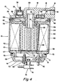
- a fuel filter assembly 10 for filtering and heating fuel for diesel engines and the like comprises a filter head 12, a spin-on element 13 and a collection bowl 15.
- the filter head 12 is fastened to an engine or other suitable structure by a flange 16 and supports the entire fuel filter assembly 10.
- the filter head 12 is a die cast head and includes therein an inlet port 18, an outlet port 19, and connected respectively thereto, an inlet chamber 21 and an outlet chamber 22.
- the filter head 12 is a generally circular structure having a flat annular mounting surface 24 at the lower portion thereof for sealing engagement by the spin-on element 13 and further includes an annular cavity 25 forming a part of the inlet chamber 21 and surrounding a circular portion of the outlet chamber 22.
- a heater assembly 26 is received in the cavity 25 of the inlet chamber 21 and is secured in place by a threaded tube 28, the bore of which communicates with the outlet chamber 22.
- the filter head 12 further comprises a vent port 29 and a vacuum switch port 30, both of which are in fluid communication with the outlet chamber 22 and a return check valve port 31 which is in fluid communication with the inlet chamber 21.
- the filter head 12 includes a heater port 32 which houses a feed through connector 34 and a thermostat 35 for supplying electrical power to the heater assembly 26.
- the fuel supply system for a typical diesel engine is depicted in schematic form as comprising a fuel tank 40, a fuel pump 41, the fuel filter assembly 10, an injection pump 42 and a plurality of injectors 44.
- Typical fuel lines are interconnected among the various components of the system with, for example, a fuel line 45 connected to the inlet port 18 of the filter assembly 10 and with various bleed lines 46 providing a fuel return path from each of the injectors 44 to the fuel tank 40.
- a bleed line 47 is also depicted as returning fuel from the injection pump 42 to the fuel tank 40 as a part of the fuel system.
- bleed lines 48 are shown as connected between the fuel filter assembly 10 and the fuel tank 40 by way of bleed lines such as 46, this being the line which is connected from a return check valve 50 connected at the return check valve port 31.
- the port 31 is connected to the inlet chamber 21 of the filter head 12 for venting air and fuel from the fuel filter assembly 10, which air is entrained in the diesel fuel or which is trapped therein upon change of the spin-on element 13.
- the spin-on element 13 can be seen to comprise a cylindrical casing 52 which houses a filter element 54 for separating out contaminants and particulate matter in the fuel passing through the filter assembly.
- the filter element 54 comprises a filter medium 55 which is an annulus or loop of pleated paper element well known in the art or any other form of filter medium which would be suitable for separating out contaminants.
- the filter medium 55 is housed between an upper end cap 56 and a lower end cap 57 each of which comprise generally circular sheet metal plates for supporting the filter structure. Both of the end caps 56, 57 include circular ridges at the outer periphery thereof which extend inwardly of the filter medium 55 further to contain the structure.
- a perforated central support tube 58 is housed in the centre of the structure centrally of the filter medium 55 and all of the elements are secured together by means of potting compound closely adjacent the inner surfaces 59 of the upper and bottom end caps 56, 57 respectively. Therefore it is apparent that the filter medium 55 divides the spin-on element casing 52 into an outer peripheral fuel chamber 60 and a central fuel chamber 61.
- the filter element 54 further includes a rigid top plate 62 which is generally of circular configuration having a central threaded aperture 64 and a plurality of openings 65 which surround the central aperture 64 and provide a path for fuel flow through the top plate 62.
- An annular gasket 66 is provided above the top plate 62 and is retained in place on the spin-on element 13 to provide sealed engagement with the mounting surface 24 of the filter head 12.
- the spin on element 13 further comprises an inner annular gasket 68 which is pressed in place in a central opening in the upper end cap 56 and retained in position by being trapped between the end cap 56 and the top plate 62.
- the gasket 68 provides a seal for the spin-on element 13 when in engagement with a smooth portion of the outer periphery of the threaded tube 28 as depicted in Figure 4.
- the spin-on element 13 further comprises an adaptor ring 69 which is a continuous ring which can lie flat and be sealed against a lower turned-in edge of the casing 52 by means of a polyester adhesive material.
- the adaptor ring 69 includes a plurality of radially oriented and circumferentially distributed upstanding ribs 70 and a depending annular threaded portion 71 for securement of the collection bowl 15.
- the upstanding ribs 70 provide fluid paths 72 therebetween for flow of contaminants and the like to the interior of the collection bowl 15.
- the spin-on element 13 is fabricated by placement and adhesion of the adaptor ring 69 against the lower turned-in end of the casing 52. Thereafter, the filter element 54, as a subassembly, is positioned on the ribs 70 of the adaptor ring 69 thereby forming the fluid paths 72.
- the inner annular gasket 68 is placed in position in the central opening of the upper end cap 56 and the top plate 62 placed thereover with the material forming the central threaded aperture 64 pressed into an inner peripheral opening of the gasket 68.
- a thin metal plate covering the top plate 62 and welded in place thereto is then secured to the casing 52 by means of a rolled edge to secure the entire spin-on element assembly 13.
- the annular gasket 66 is positioned in an annular groove above the top plate 62 and is retained in place therein by several indented portions.
- this device comprises a cup-like member having a bottom wall 73 and a peripheral side wall 74.
- the side wall 74 has an internally threaded portion thereon and culminates at the upper edge in an annular groove in which an o-ring seal 76 is disposed for sealing engagement with the lower surface of the turned-in edge of the casing 52.
- the collection bowl 15 has a filter drain assembly 78 mounted in the lower portion thereof for disposing of water accumulated in the collection bowl and for draining of the entire spin-on element 13 upon replacement thereof.
- the filter drain assembly 78 comprises a pop-up valve 79 mounted in an opening in the bottom wall 73 of the collection bowl 15 as well as a vent valve 80 which can allow air to be drawn into the collection bowl 15 to relieve the partial vacuum created therein on opening of the pop-up valve 79.
- a water sensor probe 82 mounted in the lower wall 73 of the collection bowl 15 is an insulated electrical conductor which can achieve electrical continuity with fluid in the collection bowl when the fluid rises to a level to contact its exposed inner end.
- the heater assembly 26 is shown in more detail in Figures 5 and 6 as comprising an annular container formed with an upper insulating cover 84 and a lower conductive cup 85 which are joined at their margins and staked in place to provide a fuel heater enclosure 86 of generally annular configuration.
- the upper insulated cover 84 is depressed at a central portion thereof to form the inner margin of the annular enclosure 86 and is received on a central stud in the filter head 12 for securement in the inlet chamber 21.
- the lower conductive cup 85 is depressed at two locations about its lower wall, spaced 180 o apart for receipt of a pair of heater element discs 88 which are the devices which supply the thermal energy for warming of the diesel fuel passing through the heater assembly 26.
- the heater discs 88 are positive temperature coefficient (PTC) semiconductor elements which are commonly employed for similar purposes and which have a self-regulating thermal capability due to their relatively high positive temperature coefficient. This provides regulation of the electrical input and thus, the power output of the heater discs.
- a conductive plate of generally half-ring configuration is joined to the inner end of the feed through the connector 34 and the thermostat 35 to supply electrical power to one side of the heater discs 88 by means of plurality of spring fingers 90 depending from a conductive plate 89 at the location of each of the discs 88.
- the lower conductive cup 85 is in contact with the threaded tube 28 which in turn is threaded into the filter head 12, and with all of these devices made of highly conductive metal, this arrangement provides an efficient earth connection for the heater assembly 26.
- the heater assembly 26 includes an outlet aperture 92 in the lower conductive cup 85, an inlet aperture 94 in the upper insulated cover 84 and a barrier comprising a radially positioned wall 95 extending downwardly from the upper cover 84 to the lower conductive cup 85 to provide a blockage in the annular fuel enclosure 86 in the heater assembly 26.
- fuel entering the inlet port 18 and the inlet chamber 21 of the filter head 12 is directed to the upper cover 84 of the heater assembly 26 and into the inlet opening 94, to be passed in a circuitous path of approximately 360 o over and around the heater elements discs 88 to the outlet opening 92 in the lower conductive cup 85.
- Fuel then flows to the space between the filter head 12 and the top plate 62 of the spin-on element 13 to pass through the openings 65 in the top plate 62 and into the outer peripheral fuel chamber 60.
- moisture and other contaminants are collected on the outer surface thereof and drop to the bottom of the casing 52, thereafter to pass through the fluid paths 72 in the adaptor ring 69 and to be collected in the collection bowl 15.
- Fuel that traverses the filter medium 55 enters the perforated tube 58 and the central fuel chamber 61 and is delivered through the threaded tube 28 to the outlet chamber 22 and the outlet port 19 for delivery to a further part of the fuel system of the vehicle.
- the filter pop up valve 79 of the filter drain assembly To replace the spin-on element 13 it is only necessary to actuate the filter pop up valve 79 of the filter drain assembly and remove not only contaminants from the collection bowl 15 but also fuel that may be entrained in the filter medium 55, the peripheral fuel chamber 60 and the cavities located above the spin-on element 13. The element 13 may then be unthreaded from the filter head 12 and removed therefrom for replacement purposes. During this procedure, the collection bowl 15 is unthreaded from the spin-on element 13, a new spin-on element introduced to which the collection bowl 15 is threaded and secured in position and the entire new spin-on element 13 attached to the threaded tube 28 to be secured to the filter head 12.
- a vacuum could be applied to a vent valve 96 which is merely a check valve threaded into the vent port 29 to draw fuel throughout the filter assembly until the outlet chamber 22 is filled.
- a fuel supply pump such as the pump 41 could be actuated to force fluid through the filter assembly until it was again filled.
- air that has been introduced into the assembly during replacement of the spin-on element 13 will tend to rise to the top of the inlet chamber 21 and air that is entrained in the diesel fuel will similarly rise to the top of the inlet chamber 21.
- the return check valve 50 will become operative to vent air from the chamber and fluid as well to the return line 48 to be returned eventually to the fuel tank 40. In this manner a considerable amount of air which had previously been trapped in the fuel filter assembly will be expunged therefrom to provide more reliable operating characteristics.
- the return check valve 50 comprises a metal body member 101 having a hexagonal portion thereon, an externally threaded inner end, and a central axial stepped bore 103 therein.
- the outer end portion of the body 101 is a reduced tubular part having barbs 104 thereon and a closure member 105 at the outer end to provide a fitting for push-on tubing or the like to serve as a drain line for return of fuel to a fuel tank 40.
- the closure member 105 includes a small central orifice 106 therein which is typically of 1 mm (0.040 inches) in diameter and which serves as a device to restrict flow of fuel through the return check valve 50.
- a check valve 110 Seated in the bore 103, against a shoulder 108 is a check valve 110 which is a single piece elastomeric part in the form of a duck-bill valve.
- the check valve 110 comprises a circular entrance ring 114 of relatively thick proportions, a tubular portion 115 and a pair of lips 116 in the shape of a duck's bill which provides a check valve function for the valve 110.
- the lips 116 taper inwardly from the tubular portion 115 and are closely adjacent one another at their downstream end to provide a seal against fluid flow in the reverse direction, but are sufficiently flexible to be distended slightly upon fluid flow from the inlet of the check valve 50 toward the orifice 106 to provide very little resistance to such fluid flow.
- air that is trapped within the inlet chamber 21 of the filter head 12 passes with the fluid through the check valve 50 to the fuel tank 40.
- the relatively small size of the outlet orifice 106 in the return check valve 50 ensures that while a substantially continuous flow of fluid is provided such flow will be restricted to a relatively minimal amount sufficient to ensure clearance of entrapped air in the filter head 12.
- a vacuum switch 98 of conventional variety is threaded in the vacuum switch port 30 of the filter head 12 in fluid communication with the outlet port 19 so as to provide an indication of the pressure level in this chamber and a signal of clogging or contamination of the filter medium 55 so that replacement can be performed as necessary.
Description
- The invention relates to a fuel filter used to filter and heat diesel fuel, the filter including heater means therein to elevate the temperature of the fuel to prevent buildup of residues and subsequent clogging of the fuel system.
- The application of heater devices to diesel fuel filters has become accepted in the field because of the successful results obtained and the fact that much wider temperature ranges can be accommodated, which had previously introduced problems of clogging and plugging of the filters. While initially heaters were adapted to preexisting filter devices, it has now become commonplace to incorporate the heater as an integral part of the filter assembly and to achieve an efficient heat transfer with the fuel being passed to the filter element.
- In particular, heater elements have been applied to the spin-on type of fuel filter wherein it is desired not only to obtain an efficient heat transfer relationship, but also to provide an efficient housing structure which can be incorporated safely into an engine compartment and still provide relatively free access for filter changes, maintenance and the like. Particular attention has been paid in such devices to the retention of a quantity of fuel in the filter head and/or the heater element so that when the filter element is exchanged there is not an excessive spillage of fuel. An alternate scheme is to provide means for efficiently draining the filter casing or cartridge prior to removal of the spin-on element so as to avoid or minimize the fuel spillage problem.
- One device of this type is shown in Patent specification US-A-4 387 691 wherein a particular form of heater structure is employed in the filter head of a filter assembly which includes a spin-on type of filter element. Particular attention is paid in this disclosure to the routing of fluids through the heater structure and the filter medium so as to achieve an efficient and advantageous heat transfer relationship.
- A similar arrangement of diesel fuel heater is shown in Patent specification US-A-4 406 785 wherein a plurality of PTC fuel heater elements are disposed on a conductive plate and located within the filter head of a fuel filter assembly to achieve the heat transfer relationship. In this form of apparatus, a circuitous path of travel for fluid flow through the heater element is provided which is about 360° in angular length and the heater is directly operative in the fuel path.
- Still another form of prior art device is shown in Patent specification US-A-4 596 224 wherein a separate insulative housing is provided for the fuel heater, which housing is disposed between the filter head and the spin-on element and in which, again, a circuitous path of travel for the fluid flow is provided.
- A more recent disclosure is made in Patent specification US-A-4 608 161 wherein a fuel heater structure is disposed in the filter head of the filter assembly. In this disclosure special structure is provided between the filter head and the spin-on filter element to displace fuel which might have been trapped in this location and which avoids significant fuel spillage upon element replacement. A vent duct is provided in the filter head. The preamble of claim corresponds to US-A-4 608 161
Patent specification EP-A-166160 discloses a filter which has a closed chamber at the head thereof with an outlet tube closed by a bimetal disc such that, when fuel is cold, no fuel can flow out of the outlet tube and resulting fuel pressure opens a non-return valve to allow fuel to flow into a filter housing to warm the fuel flowing in the filter media and assist flow thereof. - According to the invention there is provided a fuel filter assembly used to filter and heat diesel fuel and the like, comprising a filter head assembly supporting the filter assembly and interconnected with a fuel system of an engine, the filter head having an annular mounting surface thereon sealingly to receive a spin-on cylindrical element,
inlet and outlet ports in the filter head in fluid communication respectively with inlet and outlet chambers in the filter head,
an annular fuel heater in the inlet chamber effective to warm the fuel prior to passage thereof to the spin-on element,
a filter element in the spin-on element to separate out contaminants in the diesel fuel and to establish a flow path for diesel fuel between an outer peripheral fuel chamber and a central fuel chamber, the peripheral fuel chamber being in direct fluid communication with the inlet chamber in the filter head and the central fuel chamber being in direct communication with the outlet chamber in the filter head,
means releasably interconnecting the filter head and the spin-on element, and
an air vent port in the filter head,
characterised in that the fuel filter assembly is provided on the pressure side of a fuel supply pump,
the spin-on element has an annular mounting surface thereon sealingly to receive a collection bowl,
the air vent port in the filter head is externally connected to a fuel tank of the fuel system of the engine, and
the fuel filter assembly further comprises
means releasably interconnecting the spin-on element and the collection bowl, and
return check valve means in the filter head in fluid communication with the inlet chamber effective to release trapped air and to return fuel through the air vent port to the fuel tank of the fuel system of the engine to vent air and fuel from the inlet chamber after replacement of the spin-on cylindrical element. - Thus the invention can provide a heater located in the filter head of a filter assembly, which filter assembly includes a compound spin-on element comprising a casing for a filter element subassembly together with a removable threaded collection bowl. This can provide a convenient and safe mechanism for accommodating element exchange and also provide an efficient heat transfer relationship between the fuel heater and the diesel fuel passing through the filter apparatus.
- The spin-on diesel fuel filter structure can incorporate a number of features in a die cast head structure for the assembly. These include among others, the heater element and in particular the non-return check valve in fluid communication with the inlet chamber in the filter head to release trapped air and to return fuel to the fuel system of the engine. The die cast head assembly can include not only inlet and outlet ports for interconnection with the fuel system of the vehicle, but also additional ports for the provision of a vent/calibration valve and a vacuum switch, both in fluid communication with an outlet chamber in the filter head.
- The entire filter assembly can be supported by the filter head which may be attached at any convenient location in the engine compartment. Interconnection with the replacement spin-on element can be made by means of a threaded tube in the filter head which provides not only the mounting device but also a means for securing the fuel heater in the filter head and making electrical connection therewith. The fuel heater can be an annular can structure having a central mounting aperture to receive the threaded tube and comprising an upper insulating housing and a lower conductive plate which is in electrical connection with the threaded tube. A feed-through electrical contact and thermostat assembly can provide electrical power to a pair of PTC-type heater elements disposed on the conductive plate. A circuitous fuel path can be established so that a suitable heat transfer relationship is achieved with the heater elements.
- The spin-on element may comprise the removable contaminant collection bowl threadedly attached to an adaptor member secured in the spin-on element casing. The casing in turn can be supported by a rigid top plate from the threaded tube and contain therewithin the filter element subassembly comprising an annular filter medium contained within upper and lower end caps and surrounding a central perforated supported tube. A filter drain assembly and water sensor probe can be included in the collection bowl for removal of water and other contaminants or for removal of fluid preparatory to exchange of the spin-on element.
- The invention is diagrammatically illustrated by way of example in the accompanying drawings, in which:-
- Figure 1 is a schematic drawing of a fuel filter according to the invention in a typical fuel supply and return system for a diesel engine and the like;
- Figure 2 is a plan view of a fuel filter according to the invention;
- Figure 3 is an elevation of a fuel filter according to the invention;
- Figure 4 is a sectional view of a fuel filter according to the invention;
- Figure 5 is a sectional view of a filter head portion of a fuel filter according to the invention;
- Figure 6 is an underneath view of the filter head portion of Figure 5; and
- Figure 7 is a sectional view of a return check valve used in a fuel filter according to the invention.
- A
fuel filter assembly 10 for filtering and heating fuel for diesel engines and the like comprises afilter head 12, a spin-onelement 13 and acollection bowl 15. Thefilter head 12 is fastened to an engine or other suitable structure by aflange 16 and supports the entirefuel filter assembly 10. Preferably, thefilter head 12 is a die cast head and includes therein aninlet port 18, anoutlet port 19, and connected respectively thereto, aninlet chamber 21 and anoutlet chamber 22. Thefilter head 12 is a generally circular structure having a flatannular mounting surface 24 at the lower portion thereof for sealing engagement by the spin-onelement 13 and further includes anannular cavity 25 forming a part of theinlet chamber 21 and surrounding a circular portion of theoutlet chamber 22. Aheater assembly 26 is received in thecavity 25 of theinlet chamber 21 and is secured in place by a threadedtube 28, the bore of which communicates with theoutlet chamber 22. Thefilter head 12 further comprises avent port 29 and avacuum switch port 30, both of which are in fluid communication with theoutlet chamber 22 and a returncheck valve port 31 which is in fluid communication with theinlet chamber 21. Still further, thefilter head 12 includes aheater port 32 which houses a feed throughconnector 34 and athermostat 35 for supplying electrical power to theheater assembly 26. - Referring to Figure 1, the fuel supply system for a typical diesel engine is depicted in schematic form as comprising a
fuel tank 40, afuel pump 41, thefuel filter assembly 10, aninjection pump 42 and a plurality ofinjectors 44. Typical fuel lines are interconnected among the various components of the system with, for example, afuel line 45 connected to theinlet port 18 of thefilter assembly 10 and with variousbleed lines 46 providing a fuel return path from each of theinjectors 44 to thefuel tank 40. Ableed line 47 is also depicted as returning fuel from theinjection pump 42 to thefuel tank 40 as a part of the fuel system. Not depicted in Figure 1 but understood as comprising a part of the fuel system, are pressure lines between theinjection pump 42 and each of theinjectors 44 which supply fuel to the diesel engine. A furtherbleed line 48 is shown as connected between thefuel filter assembly 10 and thefuel tank 40 by way of bleed lines such as 46, this being the line which is connected from areturn check valve 50 connected at the returncheck valve port 31. In turn, theport 31 is connected to theinlet chamber 21 of thefilter head 12 for venting air and fuel from thefuel filter assembly 10, which air is entrained in the diesel fuel or which is trapped therein upon change of the spin-onelement 13. - Referring now more particularly to the cross sectional view of Figure 4, the spin-on
element 13 can be seen to comprise acylindrical casing 52 which houses afilter element 54 for separating out contaminants and particulate matter in the fuel passing through the filter assembly. Thefilter element 54 comprises afilter medium 55 which is an annulus or loop of pleated paper element well known in the art or any other form of filter medium which would be suitable for separating out contaminants. Thefilter medium 55 is housed between anupper end cap 56 and alower end cap 57 each of which comprise generally circular sheet metal plates for supporting the filter structure. Both of the end caps 56, 57 include circular ridges at the outer periphery thereof which extend inwardly of thefilter medium 55 further to contain the structure. A perforated central support tube 58 is housed in the centre of the structure centrally of thefilter medium 55 and all of the elements are secured together by means of potting compound closely adjacent theinner surfaces 59 of the upper and bottom end caps 56, 57 respectively. Therefore it is apparent that thefilter medium 55 divides the spin-on element casing 52 into an outerperipheral fuel chamber 60 and acentral fuel chamber 61. - The
filter element 54 further includes a rigidtop plate 62 which is generally of circular configuration having a central threaded aperture 64 and a plurality ofopenings 65 which surround the central aperture 64 and provide a path for fuel flow through thetop plate 62. Anannular gasket 66 is provided above thetop plate 62 and is retained in place on the spin-onelement 13 to provide sealed engagement with the mountingsurface 24 of thefilter head 12. The spin onelement 13 further comprises an innerannular gasket 68 which is pressed in place in a central opening in theupper end cap 56 and retained in position by being trapped between theend cap 56 and thetop plate 62. Thegasket 68 provides a seal for the spin-onelement 13 when in engagement with a smooth portion of the outer periphery of the threadedtube 28 as depicted in Figure 4. At the lower portion thereof, the spin-onelement 13 further comprises anadaptor ring 69 which is a continuous ring which can lie flat and be sealed against a lower turned-in edge of thecasing 52 by means of a polyester adhesive material. Theadaptor ring 69 includes a plurality of radially oriented and circumferentially distributedupstanding ribs 70 and a depending annular threadedportion 71 for securement of thecollection bowl 15. Theupstanding ribs 70 providefluid paths 72 therebetween for flow of contaminants and the like to the interior of thecollection bowl 15. - The spin-on
element 13 is fabricated by placement and adhesion of theadaptor ring 69 against the lower turned-in end of thecasing 52. Thereafter, thefilter element 54, as a subassembly, is positioned on theribs 70 of theadaptor ring 69 thereby forming thefluid paths 72. The innerannular gasket 68 is placed in position in the central opening of theupper end cap 56 and thetop plate 62 placed thereover with the material forming the central threaded aperture 64 pressed into an inner peripheral opening of thegasket 68. A thin metal plate covering thetop plate 62 and welded in place thereto is then secured to thecasing 52 by means of a rolled edge to secure the entire spin-onelement assembly 13. Theannular gasket 66 is positioned in an annular groove above thetop plate 62 and is retained in place therein by several indented portions. - Referring now to the
collection bowl 15 shown at the lower portion of the spin-onelement 13 in Figure 4, this device comprises a cup-like member having abottom wall 73 and aperipheral side wall 74. Theside wall 74 has an internally threaded portion thereon and culminates at the upper edge in an annular groove in which an o-ring seal 76 is disposed for sealing engagement with the lower surface of the turned-in edge of thecasing 52. Thecollection bowl 15 has afilter drain assembly 78 mounted in the lower portion thereof for disposing of water accumulated in the collection bowl and for draining of the entire spin-onelement 13 upon replacement thereof. Thefilter drain assembly 78 comprises a pop-upvalve 79 mounted in an opening in thebottom wall 73 of thecollection bowl 15 as well as avent valve 80 which can allow air to be drawn into thecollection bowl 15 to relieve the partial vacuum created therein on opening of the pop-upvalve 79. Further mounted in thelower wall 73 of thecollection bowl 15 is awater sensor probe 82 which is an insulated electrical conductor which can achieve electrical continuity with fluid in the collection bowl when the fluid rises to a level to contact its exposed inner end. - The
heater assembly 26 is shown in more detail in Figures 5 and 6 as comprising an annular container formed with an upper insulatingcover 84 and a lowerconductive cup 85 which are joined at their margins and staked in place to provide afuel heater enclosure 86 of generally annular configuration. The upperinsulated cover 84 is depressed at a central portion thereof to form the inner margin of theannular enclosure 86 and is received on a central stud in thefilter head 12 for securement in theinlet chamber 21. The lowerconductive cup 85 is depressed at two locations about its lower wall, spaced 180o apart for receipt of a pair ofheater element discs 88 which are the devices which supply the thermal energy for warming of the diesel fuel passing through theheater assembly 26. Theheater discs 88 are positive temperature coefficient (PTC) semiconductor elements which are commonly employed for similar purposes and which have a self-regulating thermal capability due to their relatively high positive temperature coefficient. This provides regulation of the electrical input and thus, the power output of the heater discs. A conductive plate of generally half-ring configuration is joined to the inner end of the feed through theconnector 34 and thethermostat 35 to supply electrical power to one side of theheater discs 88 by means of plurality ofspring fingers 90 depending from aconductive plate 89 at the location of each of thediscs 88. As noted, the lowerconductive cup 85 is in contact with the threadedtube 28 which in turn is threaded into thefilter head 12, and with all of these devices made of highly conductive metal, this arrangement provides an efficient earth connection for theheater assembly 26. - The feed through
connector 34 and thethermostat 35 are combined as a subassembly for insertion in an opening in the upperinsulated cover 84, the latter being sealed by means of an o-ring engagement with thefilter head 12 while thethermostat 35 itself is sealed on the interior with a further o-ring. As can be seen in Figure 6, theheater assembly 26 includes anoutlet aperture 92 in the lowerconductive cup 85, aninlet aperture 94 in the upperinsulated cover 84 and a barrier comprising a radially positionedwall 95 extending downwardly from theupper cover 84 to the lowerconductive cup 85 to provide a blockage in theannular fuel enclosure 86 in theheater assembly 26. Thus, fuel entering theinlet port 18 and theinlet chamber 21 of thefilter head 12 is directed to theupper cover 84 of theheater assembly 26 and into theinlet opening 94, to be passed in a circuitous path of approximately 360o over and around theheater elements discs 88 to the outlet opening 92 in the lowerconductive cup 85. Fuel then flows to the space between thefilter head 12 and thetop plate 62 of the spin-onelement 13 to pass through theopenings 65 in thetop plate 62 and into the outerperipheral fuel chamber 60. As fuel traverses thefilter medium 55, moisture and other contaminants are collected on the outer surface thereof and drop to the bottom of thecasing 52, thereafter to pass through thefluid paths 72 in theadaptor ring 69 and to be collected in thecollection bowl 15. Fuel that traverses thefilter medium 55 enters the perforated tube 58 and thecentral fuel chamber 61 and is delivered through the threadedtube 28 to theoutlet chamber 22 and theoutlet port 19 for delivery to a further part of the fuel system of the vehicle. - To replace the spin-on
element 13 it is only necessary to actuate the filter pop upvalve 79 of the filter drain assembly and remove not only contaminants from thecollection bowl 15 but also fuel that may be entrained in thefilter medium 55, theperipheral fuel chamber 60 and the cavities located above the spin-onelement 13. Theelement 13 may then be unthreaded from thefilter head 12 and removed therefrom for replacement purposes. During this procedure, thecollection bowl 15 is unthreaded from the spin-onelement 13, a new spin-on element introduced to which thecollection bowl 15 is threaded and secured in position and the entire new spin-onelement 13 attached to the threadedtube 28 to be secured to thefilter head 12. At this point a vacuum could be applied to avent valve 96 which is merely a check valve threaded into thevent port 29 to draw fuel throughout the filter assembly until theoutlet chamber 22 is filled. Alternatively a fuel supply pump such as thepump 41 could be actuated to force fluid through the filter assembly until it was again filled. In this procedure air that has been introduced into the assembly during replacement of the spin-onelement 13 will tend to rise to the top of theinlet chamber 21 and air that is entrained in the diesel fuel will similarly rise to the top of theinlet chamber 21. At this location thereturn check valve 50 will become operative to vent air from the chamber and fluid as well to thereturn line 48 to be returned eventually to thefuel tank 40. In this manner a considerable amount of air which had previously been trapped in the fuel filter assembly will be expunged therefrom to provide more reliable operating characteristics. - Referring to the Figure 7, the
return check valve 50 comprises ametal body member 101 having a hexagonal portion thereon, an externally threaded inner end, and a central axial stepped bore 103 therein. The outer end portion of thebody 101 is a reduced tubularpart having barbs 104 thereon and aclosure member 105 at the outer end to provide a fitting for push-on tubing or the like to serve as a drain line for return of fuel to afuel tank 40. Theclosure member 105 includes a smallcentral orifice 106 therein which is typically of 1 mm (0.040 inches) in diameter and which serves as a device to restrict flow of fuel through thereturn check valve 50. Aninner end 107 of thebore 103 is enlarged and thebore 103 is stepped in several locations toward the outlet end at theorifice 106. Seated in thebore 103, against ashoulder 108 is acheck valve 110 which is a single piece elastomeric part in the form of a duck-bill valve. Thecheck valve 110 comprises acircular entrance ring 114 of relatively thick proportions, atubular portion 115 and a pair oflips 116 in the shape of a duck's bill which provides a check valve function for thevalve 110. Thelips 116 taper inwardly from thetubular portion 115 and are closely adjacent one another at their downstream end to provide a seal against fluid flow in the reverse direction, but are sufficiently flexible to be distended slightly upon fluid flow from the inlet of thecheck valve 50 toward theorifice 106 to provide very little resistance to such fluid flow. Similarly, air that is trapped within theinlet chamber 21 of thefilter head 12, passes with the fluid through thecheck valve 50 to thefuel tank 40. The relatively small size of theoutlet orifice 106 in thereturn check valve 50 ensures that while a substantially continuous flow of fluid is provided such flow will be restricted to a relatively minimal amount sufficient to ensure clearance of entrapped air in thefilter head 12. Since thereturn check valve 50 is connected from theinlet chamber 21 to thefuel tank 40 it will be noted that it is in bypass connection of thefilter medium 55 and does provide some relief for excessive pressure differentials exhibited at thefilter medium 55. Avacuum switch 98 of conventional variety is threaded in thevacuum switch port 30 of thefilter head 12 in fluid communication with theoutlet port 19 so as to provide an indication of the pressure level in this chamber and a signal of clogging or contamination of thefilter medium 55 so that replacement can be performed as necessary.
Claims (5)
- A fuel filter assembly used to filter and heat diesel fuel and the like, comprising
a filter head (12) assembly supporting the filter assembly and interconnected with a fuel system of an engine, the filter head (12) having an annular mounting surface thereon sealingly to receive a spin-on cylindrical element (13),
inlet (18) and outlet (19) ports in the filter head (12) in fluid communication respectively with inlet (21) and outlet (22) chambers in the filter head,
an annular fuel heater (26) in the inlet chamber (21) effective to warm the fuel prior to passage thereof to the spin-on element,
a filter element (54) in the spin-on element to separate out contaminants in the diesel fuel and to establish a flow path for diesel fuel between an outer peripheral fuel chamber (60) and a central fuel chamber (61), the peripheral fuel chamber (60) being in direct fluid communication with the inlet chamber (21) in the filter head (12) and the central fuel chamber (61) being in direct communication with the outlet chamber (22) in the filter head,
means releasably interconnecting the filter head (12) and
the spin-on element (13), and
an air vent port (31) in the filter head,
characterised in that the fuel filter assembly is provided on the pressure side of a fuel supply pump (41),
the spin-on element has an annular mounting surface thereon sealingly to receive a collection bowl (15),
the air vent port (31) in the filter head is externally connected (48) to a fuel tank (40) of the fuel system of the engine, and
the fuel filter assembly further comprises
means releasably interconnecting the spin-on element (13) and the collection bowl (15), and
return check valve means (50) in the filter head (12) in fluid communication with the inlet chamber (21) effective to release trapped air and to return fuel through the air vent port (31) to the fuel tank (40) of the fuel system of the engine to vent air and fuel from the inlet chamber (21) after replacement of the spin-on cylindrical element. - A fuel filter according to claim 1, wherein the return check valve means (50) comprises an elastomeric duck-bill check valve (110) supported in a body member (101) threaded into a port (31) communicating with the inlet chamber (21), the valve having a restricted orifice (106) therein to limit the flow of fuel in bypass of the filter element.
- A fuel filter according to claim 2, wherein the means releasably interconnecting the spin-on element (13) and the filter head (12) is a threaded tube (28) secured in the filter head (12) and securing the heater element in electrical engagement with the filter head.
- A fuel filter according to claim 3, wherein the threaded tube (28) is in fluid communication with the outlet chamber (22) in the filter head and establishes a path for fluid flow from the spin-on element to the outlet chamber.
- A fuel filter according to claim 4, wherein the filter head further comprises a vent port (29) and a vacuum switch port (30) in fluid communication with the outlet chamber (22) in the filter head, the vent port (29) receiving a vent valve therein to vent and fill the outlet chamber (22) and the vacuum switch port (30) providing access to the outlet chamber to monitor the vacuum pressure in the outlet chamber.
Applications Claiming Priority (2)
| Application Number | Priority Date | Filing Date | Title |
|---|---|---|---|
| US3283487A | 1987-03-30 | 1987-03-30 | |
| US32834 | 1987-03-30 |
Publications (2)
| Publication Number | Publication Date |
|---|---|
| EP0285416A1 EP0285416A1 (en) | 1988-10-05 |
| EP0285416B1 true EP0285416B1 (en) | 1993-11-18 |
Family
ID=21867073
Family Applications (1)
| Application Number | Title | Priority Date | Filing Date |
|---|---|---|---|
| EP88302884A Expired - Lifetime EP0285416B1 (en) | 1987-03-30 | 1988-03-30 | Fuel filter assembly with heater |
Country Status (4)
| Country | Link |
|---|---|
| EP (1) | EP0285416B1 (en) |
| BR (1) | BR8801423A (en) |
| CA (1) | CA1312018C (en) |
| DE (1) | DE3885639T2 (en) |
Cited By (3)
| Publication number | Priority date | Publication date | Assignee | Title |
|---|---|---|---|---|
| DE102010031341A1 (en) | 2010-07-14 | 2012-01-19 | Hengst Gmbh & Co. Kg | Fuel filter, particularly for internal combustion engine, has filter housing connected with filter head, where fuel inlet is connected to dirty side, and fuel outlet is connected to clean side |
| DE102010033743A1 (en) * | 2010-08-07 | 2012-02-09 | Mahle International Gmbh | Fluid filter i.e. fuel filter, has flow throughable heating device heating fluid to be filtered and arranged above upper end disc, and channel system arranged between heating device and lid |
| DE102013209491A1 (en) * | 2013-05-22 | 2014-11-27 | Mahle International Gmbh | Fuel filter for an internal combustion engine |
Families Citing this family (15)
| Publication number | Priority date | Publication date | Assignee | Title |
|---|---|---|---|---|
| US5643446A (en) * | 1985-05-14 | 1997-07-01 | Parker Hannifin Corporation | Fuel filter and priming pump |
| US4855041A (en) * | 1987-04-24 | 1989-08-08 | Parker Hannifin Corporation | Fluid filter drain assembly |
| DE4239099C2 (en) * | 1992-11-20 | 2001-02-15 | Mahle Filtersysteme Gmbh | Fuel filter |
| AU1316497A (en) * | 1996-01-22 | 1997-08-20 | Centrax Limited | Oil reclamation device |
| GB2309174A (en) * | 1996-01-22 | 1997-07-23 | Richard Henry Howard Barr | Oil reclamation device |
| GB2333246A (en) * | 1998-01-14 | 1999-07-21 | Lucas Ind Plc | Rectangular fuel filter housing with rotatable filter head |
| DE19807373A1 (en) * | 1998-02-21 | 1999-08-26 | Bosch Gmbh Robert | Filter device in modular design |
| DE19955206A1 (en) * | 1999-11-17 | 2001-07-05 | Mann & Hummel Filter | Fuel filter |
| US6631853B2 (en) * | 2001-04-09 | 2003-10-14 | Siemens Diesel Systems Technologies, Llc | Oil activated fuel injector control valve |
| DE20116185U1 (en) * | 2001-10-02 | 2003-03-13 | Hengst Gmbh & Co Kg | Fuel filter with raw side vent valve |
| US7354462B2 (en) | 2002-10-04 | 2008-04-08 | Chevron U.S.A. Inc. | Systems and methods of improving diesel fuel performance in cold climates |
| DE102017007270A1 (en) * | 2017-08-01 | 2019-02-07 | Hydac Fluidcarecenter Gmbh | filter element |
| JPWO2019069897A1 (en) * | 2017-10-06 | 2020-11-05 | ヤマシンフィルタ株式会社 | Filter device |
| CN111502878B (en) * | 2020-05-09 | 2021-06-25 | 三一重机有限公司 | Fuel filter and mechanical equipment |
| CN113368578A (en) * | 2021-06-18 | 2021-09-10 | 无锡润滤机械设备有限公司 | Medicine preparation is with filtration washing drying all-in-one |
Citations (2)
| Publication number | Priority date | Publication date | Assignee | Title |
|---|---|---|---|---|
| GB2028921A (en) * | 1978-08-25 | 1980-03-12 | Daimler Benz Ag | Fuel-supply Arrangement |
| EP0166160A1 (en) * | 1984-06-22 | 1986-01-02 | Robert Bosch Gmbh | Diesel fuel filter |
Family Cites Families (8)
| Publication number | Priority date | Publication date | Assignee | Title |
|---|---|---|---|---|
| US3674043A (en) * | 1970-06-26 | 1972-07-04 | Neil C Norton | Method of preventing vapor lock during engine operation and of fuel leakage to carburetor after engine stoppage |
| US4387691A (en) * | 1980-11-07 | 1983-06-14 | Texas Instruments Incorporated | Diesel fuel filter system |
| US4406785A (en) * | 1981-12-24 | 1983-09-27 | Gte Products Corporation | Diesel fuel heater |
| US4596224A (en) * | 1983-04-29 | 1986-06-24 | Gte Products Corporation | Diesel fuel heater with fuel reservoir means |
| US4602605A (en) * | 1984-02-06 | 1986-07-29 | Adkins James L | Entering fuel injection system of a diesel engine |
| DE3415522C1 (en) * | 1984-04-26 | 1985-11-07 | Daimler-Benz Ag, 7000 Stuttgart | Heated fuel filter for diesel engines |
| US4676895A (en) * | 1984-06-25 | 1987-06-30 | Davco Manufacturing Corp. | Fluid flow baffle for fuel processor |
| DE3671501D1 (en) * | 1985-02-28 | 1990-06-28 | Vernay Laboratories | FUEL INLET KIT FOR CARBURETTOR. |
-
1988
- 1988-03-28 CA CA000562631A patent/CA1312018C/en not_active Expired - Lifetime
- 1988-03-29 BR BR8801423A patent/BR8801423A/en not_active IP Right Cessation
- 1988-03-30 EP EP88302884A patent/EP0285416B1/en not_active Expired - Lifetime
- 1988-03-30 DE DE88302884T patent/DE3885639T2/en not_active Expired - Lifetime
Patent Citations (2)
| Publication number | Priority date | Publication date | Assignee | Title |
|---|---|---|---|---|
| GB2028921A (en) * | 1978-08-25 | 1980-03-12 | Daimler Benz Ag | Fuel-supply Arrangement |
| EP0166160A1 (en) * | 1984-06-22 | 1986-01-02 | Robert Bosch Gmbh | Diesel fuel filter |
Cited By (3)
| Publication number | Priority date | Publication date | Assignee | Title |
|---|---|---|---|---|
| DE102010031341A1 (en) | 2010-07-14 | 2012-01-19 | Hengst Gmbh & Co. Kg | Fuel filter, particularly for internal combustion engine, has filter housing connected with filter head, where fuel inlet is connected to dirty side, and fuel outlet is connected to clean side |
| DE102010033743A1 (en) * | 2010-08-07 | 2012-02-09 | Mahle International Gmbh | Fluid filter i.e. fuel filter, has flow throughable heating device heating fluid to be filtered and arranged above upper end disc, and channel system arranged between heating device and lid |
| DE102013209491A1 (en) * | 2013-05-22 | 2014-11-27 | Mahle International Gmbh | Fuel filter for an internal combustion engine |
Also Published As
| Publication number | Publication date |
|---|---|
| CA1312018C (en) | 1992-12-29 |
| DE3885639T2 (en) | 1994-03-10 |
| BR8801423A (en) | 1988-11-08 |
| EP0285416A1 (en) | 1988-10-05 |
| DE3885639D1 (en) | 1993-12-23 |
Similar Documents
| Publication | Publication Date | Title |
|---|---|---|
| US4997555A (en) | Fuel filter assembly with heater | |
| US5244571A (en) | Fuel filter assembly with heater | |
| US5622623A (en) | Fuel filter element | |
| EP0285416B1 (en) | Fuel filter assembly with heater | |
| US4437986A (en) | Separating device and cartridge therefor | |
| US4470301A (en) | Probe and drain assembly for fuel oil/water separator | |
| US4502955A (en) | Filter assembly | |
| US4976852A (en) | Fuel filter | |
| US5017285A (en) | Fuel filter and cartridge assembly | |
| US5084170A (en) | Fuel filter | |
| CA1137842A (en) | Fuel filtering device for engine | |
| US6248236B1 (en) | Double pass fuel filter assembly | |
| US4491120A (en) | Fuel conditioner | |
| EP0168160B1 (en) | Filter block mounted fuel processor apparatus | |
| US5958237A (en) | Fuel filter and water separator apparatus with integrated fuel pump | |
| US4579653A (en) | Side-by-side fuel processor apparatus | |
| GB2115305A (en) | Fuel filter | |
| WO1998019770A1 (en) | Fuel filter and water separator apparatus with heater | |
| GB2140319A (en) | Diesel engine fuel filter | |
| US4618423A (en) | Disposable fuel filter/water separator element | |
| GB2272652A (en) | A fuel filter | |
| US4646703A (en) | Fuel heater | |
| CN115539263B (en) | Diesel oil filter | |
| EP0844382A2 (en) | Fuel filter |
Legal Events
| Date | Code | Title | Description |
|---|---|---|---|
| PUAI | Public reference made under article 153(3) epc to a published international application that has entered the european phase |
Free format text: ORIGINAL CODE: 0009012 |
|
| AK | Designated contracting states |
Kind code of ref document: A1 Designated state(s): DE FR GB IT |
|
| 17P | Request for examination filed |
Effective date: 19890318 |
|
| 17Q | First examination report despatched |
Effective date: 19900921 |
|
| GRAA | (expected) grant |
Free format text: ORIGINAL CODE: 0009210 |
|
| AK | Designated contracting states |
Kind code of ref document: B1 Designated state(s): DE FR GB IT |
|
| ITF | It: translation for a ep patent filed |
Owner name: AVV. SALVATORE LA CIURA |
|
| REF | Corresponds to: |
Ref document number: 3885639 Country of ref document: DE Date of ref document: 19931223 |
|
| ET | Fr: translation filed | ||
| PLBE | No opposition filed within time limit |
Free format text: ORIGINAL CODE: 0009261 |
|
| STAA | Information on the status of an ep patent application or granted ep patent |
Free format text: STATUS: NO OPPOSITION FILED WITHIN TIME LIMIT |
|
| 26N | No opposition filed | ||
| REG | Reference to a national code |
Ref country code: GB Ref legal event code: IF02 |
|
| PGFP | Annual fee paid to national office [announced via postgrant information from national office to epo] |
Ref country code: GB Payment date: 20070214 Year of fee payment: 20 |
|
| PGFP | Annual fee paid to national office [announced via postgrant information from national office to epo] |
Ref country code: DE Payment date: 20070226 Year of fee payment: 20 |
|
| PGFP | Annual fee paid to national office [announced via postgrant information from national office to epo] |
Ref country code: IT Payment date: 20070606 Year of fee payment: 20 |
|
| REG | Reference to a national code |
Ref country code: GB Ref legal event code: PE20 Expiry date: 20080329 |
|
| PGFP | Annual fee paid to national office [announced via postgrant information from national office to epo] |
Ref country code: FR Payment date: 20070212 Year of fee payment: 20 |
|
| PG25 | Lapsed in a contracting state [announced via postgrant information from national office to epo] |
Ref country code: GB Free format text: LAPSE BECAUSE OF EXPIRATION OF PROTECTION Effective date: 20080329 |