EP0285204B1 - Device and relative method for intermittently storing and returning yarn during the winding of conical bobbins fed with yarn at constant speed - Google Patents
Device and relative method for intermittently storing and returning yarn during the winding of conical bobbins fed with yarn at constant speed Download PDFInfo
- Publication number
- EP0285204B1 EP0285204B1 EP88200490A EP88200490A EP0285204B1 EP 0285204 B1 EP0285204 B1 EP 0285204B1 EP 88200490 A EP88200490 A EP 88200490A EP 88200490 A EP88200490 A EP 88200490A EP 0285204 B1 EP0285204 B1 EP 0285204B1
- Authority
- EP
- European Patent Office
- Prior art keywords
- yarn
- bobbin
- storage
- arm
- swing
- Prior art date
- Legal status (The legal status is an assumption and is not a legal conclusion. Google has not performed a legal analysis and makes no representation as to the accuracy of the status listed.)
- Expired
Links
- 238000004804 winding Methods 0.000 title claims description 36
- 238000000034 method Methods 0.000 title description 5
- 238000003860 storage Methods 0.000 claims description 60
- 230000002457 bidirectional effect Effects 0.000 claims description 12
- 230000007423 decrease Effects 0.000 claims description 7
- 230000002688 persistence Effects 0.000 claims 1
- 230000015572 biosynthetic process Effects 0.000 description 19
- 238000009987 spinning Methods 0.000 description 13
- 230000003287 optical effect Effects 0.000 description 4
- 230000008569 process Effects 0.000 description 4
- 230000009471 action Effects 0.000 description 3
- 230000008901 benefit Effects 0.000 description 3
- 230000003247 decreasing effect Effects 0.000 description 3
- 230000007547 defect Effects 0.000 description 3
- 229910000831 Steel Inorganic materials 0.000 description 2
- 230000004913 activation Effects 0.000 description 2
- 238000006073 displacement reaction Methods 0.000 description 2
- 238000009304 pastoral farming Methods 0.000 description 2
- 230000000737 periodic effect Effects 0.000 description 2
- 239000010959 steel Substances 0.000 description 2
- 230000000903 blocking effect Effects 0.000 description 1
- 230000008859 change Effects 0.000 description 1
- 238000006243 chemical reaction Methods 0.000 description 1
- 238000010276 construction Methods 0.000 description 1
- 230000008021 deposition Effects 0.000 description 1
- 230000000694 effects Effects 0.000 description 1
- 230000001788 irregular Effects 0.000 description 1
- 230000002427 irreversible effect Effects 0.000 description 1
- 238000012423 maintenance Methods 0.000 description 1
- 238000004519 manufacturing process Methods 0.000 description 1
- 238000012986 modification Methods 0.000 description 1
- 230000004048 modification Effects 0.000 description 1
- 238000012544 monitoring process Methods 0.000 description 1
- 238000007383 open-end spinning Methods 0.000 description 1
- 230000010355 oscillation Effects 0.000 description 1
- 230000000750 progressive effect Effects 0.000 description 1
- 230000009467 reduction Effects 0.000 description 1
- 239000007787 solid Substances 0.000 description 1
- 239000004753 textile Substances 0.000 description 1
- 238000011144 upstream manufacturing Methods 0.000 description 1
Images
Classifications
-
- B—PERFORMING OPERATIONS; TRANSPORTING
- B65—CONVEYING; PACKING; STORING; HANDLING THIN OR FILAMENTARY MATERIAL
- B65H—HANDLING THIN OR FILAMENTARY MATERIAL, e.g. SHEETS, WEBS, CABLES
- B65H59/00—Adjusting or controlling tension in filamentary material, e.g. for preventing snarling; Applications of tension indicators
- B65H59/005—Means compensating the yarn tension in relation with its moving due to traversing arrangements
-
- B—PERFORMING OPERATIONS; TRANSPORTING
- B65—CONVEYING; PACKING; STORING; HANDLING THIN OR FILAMENTARY MATERIAL
- B65H—HANDLING THIN OR FILAMENTARY MATERIAL, e.g. SHEETS, WEBS, CABLES
- B65H59/00—Adjusting or controlling tension in filamentary material, e.g. for preventing snarling; Applications of tension indicators
- B65H59/10—Adjusting or controlling tension in filamentary material, e.g. for preventing snarling; Applications of tension indicators by devices acting on running material and not associated with supply or take-up devices
- B65H59/36—Floating elements compensating for irregularities in supply or take-up of material
-
- B—PERFORMING OPERATIONS; TRANSPORTING
- B65—CONVEYING; PACKING; STORING; HANDLING THIN OR FILAMENTARY MATERIAL
- B65H—HANDLING THIN OR FILAMENTARY MATERIAL, e.g. SHEETS, WEBS, CABLES
- B65H59/00—Adjusting or controlling tension in filamentary material, e.g. for preventing snarling; Applications of tension indicators
- B65H59/38—Adjusting or controlling tension in filamentary material, e.g. for preventing snarling; Applications of tension indicators by regulating speed of driving mechanism of unwinding, paying-out, forwarding, winding, or depositing devices, e.g. automatically in response to variations in tension
-
- B—PERFORMING OPERATIONS; TRANSPORTING
- B65—CONVEYING; PACKING; STORING; HANDLING THIN OR FILAMENTARY MATERIAL
- B65H—HANDLING THIN OR FILAMENTARY MATERIAL, e.g. SHEETS, WEBS, CABLES
- B65H2701/00—Handled material; Storage means
- B65H2701/30—Handled filamentary material
- B65H2701/31—Textiles threads or artificial strands of filaments
Definitions
- the invention relates to a device for intermittently storing and releasing yarn during the winding of conical bobbins with yarn fed at constant speed from individual spinning units. More particularly, the invention relates to a yarn storage and release device in which a store for the supply of yarn and a tension compensator and regulator for the yarn being wound are combined.
- the yarn emerges at their outlet at constant speed from feed rollers and must be deposited at a speed which varies between the major diameter and minor diameter of the conical bobbin being formed.
- Tension compensators are known in the art. They comprise a deflecting roller connected to a rocker arm. Depending on the instantaneous yarn tension, or rather according to the instantaneous position of the rocker arm, the mobile deflecting roller is deviated to a varying extent from its contact or bearing position, this position being assumed by the action of a force exerted by a counterweight, a spring or a similar elastic element in contrast with the tension exerted by the yarn. These yarn tension compensators have the drawback of exerting an elastic opposing force which cannot be controlled in respect of the tension variations which can occur in the yarn in the case of non-regular storage.
- a constantly rotating substantially cylindrical drive roller rotates the conical bobbin under formation, the dimensions of which, together with the taper and angle of the winding helix determine the angular swing amplitude of the mobile rocker arm.
- the swing position of this latter which keeps a roller connected to it constantly adhering to the yarn, represents the yarn storage value, which constantly increases and decreases according to the stage in the progress of the entire yarn storage and release cycle.
- Any slippage between the bobbin drive roller and the bobbin under formation which is frequently present due to the friction drive used, increases the length of yarn stored and changes the swing position of the mobile arm which, under the action of the elastic element acting as a pulling means, is moved in the limit into an abutting position, consequently nullifying the tensioning of the yarn being collected.
- the yarn leaving the winding rollers winds with irregular turns, so prejudicing the bobbin formation and in the limit twisting about itself to create loops and tangles such as to compromise the yarn consistency.
- the tangled yarn also frequently creates obstacles such as to interrupt yarn continuity, so blocking the spinning process.
- the high yarn formation rate of spinning units means that any production hold-up in such spinning units assumes considerable importance because of the reduced rate of yarn collection on the bobbins.
- Yarn tension compensators of this type also have the drawback that if the yarn count or thickness, the type of bobbin under formation or the winding helix angle varies, they have to be adapted to this by onerous manual adjustments to the individual spinning stations, or by replacing the elastic element with another elastic element which conforms to the different operating characteristics. These devices are therefore inflexible in use.
- Devices for storing and intermittently releasing yarn are also known. These include by way of example the devices described and claimed in DE-A-1785153 and DE-A-2454917.
- Such devices have numerous drawbacks: they are insensitive to tension and even less to tension variations in the winding yarn because the storage and release element is of a type which, by means of a lever system, is completely controlled by a to-and-fro drive rod which passes along the entire machine face to operate the yarn stores of all the spinning units. They are unable to adjust the yarn tension to one or more predetermined values preset according to the type of yarn being collected or of the bobbin under formation.
- a further drawback of such devices is the presence of mobile members, such as rods or shafts, which have to be provided and mounted during the machine construction, and cannot be economically fitted later.
- Said mobile members control the operation of several storage devices and extend along the entire winding face from a position at the head of the machine. Because of the principle on which they are constructed, these devices are inflexible and unadaptable to pre-existing spinning stations or stations not provided with the aforesaid mobile members which pass along the front structure of the entire collection face.
- This known device operates very approximately and gives rise to bobbins of poor quality when owing to the need of restoring the given range of stored yarn the bobbin is either pressed against, or stopped relative to, the drive roller.
- This device is furthermore unsuitable for winding units operating at high speed.
- a change in the angular position of the tension compensator arm determines, through an electronic comparator and control unit, the adjustment of a yarn tensioner located upstream of the arm, in order to increase or decrease the yarn tension and therefore restore the previous angular position of the arm.
- This known device is however not suitable where a yarn storage and release is intermittently required like in the case of winding conical bobbins, because the compensator arm of the known device cannot perform yarn storing and releasing movements without simultaneously intervening on the yarn tensioner and causing yarn tension variations opposing such movements.
- An object of the present invention is to obviate the aforesaid drawbacks by providing an intermittent storage and release device in the winding of conical bobbins fed with yarn at constant speed, which device:
- a further object of the present invention is to provide a yarn storage and release device in which a store for the intermittent feed of yarn arid a tension compensator and regulator for the yarn being wound are combined, in a manner requiring very little maintenance.
- the device according to the invention has the advantage, for any variation in the type of yarn and for any variation in the geometrical characteristics of the winding or of the type of bobbin to be obtained, of automatically adjusting and setting the tension of the yarn being collected to a corresponding value for obtaining regular storage and release swings in accordance with the preset values and limits.
- a further advantage of the invention is that it ensures that once actuated by the drive source, the rotations in both directions for the purpose of varying the preloading of the elastic element are perfectly irreversible so that the reaction of the elastic element against the shaft or the vibration of the machine when in operation are unable to minimally modify the extent of said actuated rotations.
- the device according to the invention also has the further advantage, for any undesired variation in the position of the effective drive diameter, of automatically restoring the correct position of the effective drive diameter for regular winding of the conical bobbin under formation.
- a connection pin 1 is rigidly fixed to a swinging arm 2.
- 1 a is the position which the pin 1 assumes at the other end of its swing movement.
- the mobile arm 2 forms part of the yarn compensation and release lever system, which operates as the linear position element of a system for controlling and monitoring the yarn storage.
- 2a is the position which the mobile arm 2 assumes at that moment during its swing movement when the stored length of the yarn 18 is zero or a minimum.
- a bush or ring 3 rigidly joins together one end of the mobile arm 2 and one end of a second swinging arm 4 of the yarn storage and release lever system.
- the mobile arm 4 of the yarn compensation and release lever system operates as the actual storage and release element for the yarn 18 while also acting as the tension compensation and adjustment element for the yarn 18 being wound.
- a mobile yarn deflecting and guide roller 5 is carried by the free end of the mobile arm 4 but is able to rotate about its own axis so as not to generate grazing friction against the yarn undergoing continuous collection.
- the roller 5 has a substantially cylindrical profile
- 5a is the position which the mobile yarn deflecting and guide roller 5 assumes at that moment during its swing movement when the stored yarn length is zero or a minimum.
- a spiral elastic element 6 has an end connected to the pin 1 and stores drive energy by means of appropriate deformation resulting from the angular rotation applied by a shaft 10 which is connected to the other end of the elastic element 6.
- This element consists of a steel strip or wire or similar steel element, wound substantially as a flat Archimedes spiral.
- Sensing means in form of two position transducers 7 and 17 of optical, magnetic analog or digital type sense the yarn storage degree at the yarn storage and release means defined by elements 1-6, and convert the angular position of the end of the mobile arm 2 into an electrical signal or a series of electrical signals as a function of the yarn storage degree.
- a control unit 8 which comprises an electrial comparator and an electronic microprocessor receives and processes the signals originating from the transducers 7 and 17, to then activate a drive source 9 for regularizing the storage of yarn 18.
- the drive source 9 operates the shaft 10 to be rotated angularly so as to vary the preloading of the spiral elastic element 6 for the purpose of regularizing the storage if this has strayed outside the range of preset values.
- the shaft 10 is fixed or hinged, at or in proximity to its end, to the inner end of the spiral elastic preloading element 6.
- a yarn deflecting and guide roller 11 having a substantially cylindrical profile is connected to a base plate 13 and is free to rotate about its own axis in order not to generate grazing friction against the yarn 18 undergoing continuous collection movement.
- a yarn deflecting and guide roller 12 of substantially cylindrical profile is connected to a base plate 15 and is free to rotate about its own axis.
- the base plate 13 for the roller 11 is fixed to the machine structure, not shown on the figure.
- the base plate 15 for the roller 12 is also fixed to the machine structure.
- a pair of rollers 14 and 16 positioned along the path of the yarn 18 are pressed against each other with said yarn 18 passing between then to withdraw it at constant speed from a spinning unit of a rotor spinning machine and feed it towards the compensator device of the present invention.
- a solid or hollow shaft 20 of substantially circular cross-section is operated as a control rod for a yarn guide element 26 by means of a suitably shaped cam so as to transmit a reciprocating movement of suitable kinematic and dynamic characteristics to the yarn guide element 26.
- a drive roller 22 rotates the conical bobbin 24 under formation at a friction region 28 in the form of a narrow circular band.
- the drive shaft or rod 20 extends along the entire operational winding face of the machine.
- a blade 30 serves for deflecting the path of the yarn 18.
- Said blade 30 can be linear or shaped with more or less accentuated profiles already known in the art.
- a bobbin carrier arm 34 rototably supports the yarn bobbin 24.
- Connection cables 38 and 39 connect the transducers 7 and 17 with the control unit 8.
- a connection cable 40 connects the control unit 8 with the drive source 9. 42 indicates the swing path of the mobile arm 4 and 44 indicates the reciprocating to-and-fro movement path of the shaft 20.
- a shaft or pivot 46 coaxial with the bush 3 defines the swinging axis about which the yarn storage and intermittent release lever system swings by way of the bush 3.
- a drive shaft 48 extends along the entire winding face of the machine and rigidly supports the drive roller 22.
- a bidirectional drive unit 50 preferably consisting of a stepping motor inclines the axis of rotation of the conical bobbin 24 in one direction or the other in order to vary the line of effective contact between the bobbin 24 and the drive roller 22 to consequently obtain a controlled variation in the winding speed of the yarn 18.
- a pivot 52 defines the axis about which the bobbin carrier arm 34 rotates by virtue of the rotary movement of the bidirectional drive unit 50.
- a cam 53 is keyed onto the output shaft of the drive unit 50, the rotation of which determines the angular displacement of a lever 54, rotatably mounted on the pivot 52, and consequently the variation in the inclination of the bobbin carrier arm 34.
- 56 is the line representing the inclination of the axis of rotation of the conical bobbin 24 to a substantially vertical plane containing the axis of the drive roller 22.
- a connection cable 58 connects the control unit 8 with the drive source of the bidirectional drive unit 50.
- 60 is the line representing the angular rotation in both directions of the pivot 52.
- a transverse hub 33 rigidly connects the lever 54 and the bobbin carrier arm 34.
- the purpose of the storage and release device for the yarn 18 being wound onto the conical bobbin 24 is to adapt the varying winding speed deriving from the taper of the bobbin 24 to the constant outlet speed from the feed rollers 16 and 14.
- the average winding speed corresponds substantially to the spinning speed of tie spinning chamber.
- the ratio of the minor diameter to the major diameter of the bobbin 24 under formation determines the maximum length of yarn 18 which has to be stored and then released for each complete cycle of the yarn guide element 26.
- the mobile deflecting roller 5 generates a loop by deflecting the yarn 18 from its path.
- This loop therefore has a continuously varying amplitude and the device of the present invention is automatically controlled in accordance with this variation, to act as a compensator for the periodic tension variations which arise as a result of the periodic winding speed variations in the formation of the conical bobbin.
- the mobile deflecting roller 5 which drags the yarn into a temporary storage loop by means of the swing movement of the mobile arm 4 under the effect of the elastic preloading element 6 which provides a force opposing and balancing the tension force produced by the yarn 18 on the arm 4, has to assume different positions relative to the fixed deflecting rollers 11 and 12, within a certain range of swing.
- Said end interacts with the linear position transducers 7 and 17 without the need for mutual contact, these latter generating at their output a signal or several signals of electrical nature which are fed through the connection cables 38 and 39 to the control unit 8 which compares said signals with at least one reference signal defining a range of swing within which a predetermined yarn storage is obtained. If during the continuous winding process the storage swing end positions remain within the predetermined limits preset by the position of the two transducers 7 and 17, the control unit 8 confirms that the storage and release cycles of the yarn 18 are regular. Thus no output signal is generated at the output of the control unit 8 and no activation signal is therefore fed to the drive source 9.
- the corresponding mobile linear position of the end of the arm 2 is such as to cause the transducers 7 and 17 to generate an electrical signal or signals which after suitable comparison in the control unit 8 result to be outside the regular range of swing defined by said reference signal(s), and this gives instant rise to an output signal which activates the drive source 9.
- This latter angularly rotates the shaft 10 to increase or decrease the preloading of the spiral elastic element 6 in order to adjust the swinging lever system to swing within the regular swing range and to so return the storage to within the limits of the preset storage degree or range.
- the yarn By only slightly decreasing the average tension of the yarn being wound, the yarn slackens and becomes less inserted into the already deposited layers of yarn, and therefore proceeds to wind in the form of turns having a slightly greater diameter.
- the drive source 9 is operated and rotates the shaft 10 angularly in the direction which slightly increases the amount of preloading of the spiral elastic element 6. This latter element therefore tightens and compels the yarn, by means of the lever system 2, 3, 4 and 5, to collect on the conical bobbin 24 under an average tension which is slightly higher than the preceding situation.
- This increase in the average tension of the yarn 18 being continuously wound can be substantially rapid as there is no danger of forming knots, tangles or similar defects.
- the yarn tension can only be allowed to fluctuate within a fairly narrow range.
- the yarn tension must not assume such values as to compromise the integrity and elasticity of the yarn itself, and on the other hand must not fall below values which allow the formation of twists or knots or similar entanglement defects.
- the yarn storage and release lever system must obviously operate within the range of regular tension values, ie those which do not lead to the aforementioned drawbacks.
- the swing movement of the storage lever system subjected to the action of the spiral elastic element 6 may be insufficient or only partly sufficient to restore the intermittent swing within the range corresponding to regular storage.
- the bidirectional drive unit 50 is operated after a sufficiently short time in order to incline the axis of the conical bobbin 24 relative to the axis of the bobbin drive roller 22 so as to vary the average winding speed.
- control unit 8 immediately emits an electrical control signal which activates the bidirectional drive unit 50.
- the aforesaid limits to the preloading of the elastic element 6 are related to the limiting tensioning and slackening values allowed by the technical characteristics of the type of yarn being wound.
- the bidirectional drive unit 50 rotates the cam 53 which, by way of the lever 54 pivoted on the pivot 52, transmits an angular rotation to the bobbin carrier arm 34 to incline the axis of rotation of the conical bobbin 24 in one direction or the other relative to the axis of the bobbin drive roller 22, and consequently displace the diameter of effective contact between the conical bobbin 24 and drive roller 22 to obtain a suitable variation in the average winding speed of the yarn 18 in order to restore the storage swing to within the range of values corresponding to regular storage.
- Said electrical output signal is fed to the control unit 8 through the connection cable 39.
- the control unit 8 after identifying the type of electrical signal received from the transducer 7, correspondingly produces at its output a specific electrical control signal, which is fed through the connection cable 58 to activate the bidirectional drive unit 50. Said unit transmits an angular anticlockwise rotation to the bobbin carrier arm 34, which consequently displaces the diameter of effective contact between the conical bobbin 24 and the drive roller 22 in the decreasing diameter direction, ie towards the minor base of the bobbin.
- this displacement of the contact diameter or band takes place gradually as allowed by the drive unit 50. If the mobile deflecting roller 5 causes the storage loop in the yarn 18 to assume a position which lies below the preset minimum storage limit, the position of the mobile arm 2 causes the transducer 17 to generate an electrical output signal of value corresponding to said position.
- Said electrical output signal from the transducer 17 is fed to the control unit 8 through the connection cable 38.
- the control unit 8 after identifying the type of electrical signal received from the transducer 17, correspondingly produces at its output a specific electrical control signal, which is fed through the connection cable 58 to activate the bidirectional drive unit 50. Said unit transmits on angular clockwise rotation to the bobbin carrier arm 34, which consequently displaces the diameter or band of effective contact between the conical bobbin 24 and the drive roller 22 in the increasing diameter direction, ie towards the major base of the conical bobbin 24.
- the average winding speed decreases, ie settles at an average value which is slightly lower than the previous average value, so causing the yarn to be progressively stored in a loop of continuously increasing size, with the result that the intermittent swing of the mobile arm 4 is restored to within the predetermined regular range preset by the positions assumed by the mobile arm 2.
- the width of said regular range is predetermined by the geometrical characteristics of the winding being made together with the characteristics of the yarn and conical bobbin 24 under formation.
- the device for intermittently storing and releasing yarn during the winding of conical bobbins fed with yarn at constant speed operates very reliably, and periodically compensates the variations in yarn tension without the mobile deflecting roller 5 undergoing uncontrollable swings.
- the swinging lever system is swingable independently of the reciprocating movement of the yarn distributing element 26 associated to the bobbin 24.
- the use of the device according to the invention is not limited to the winding of conical bobbins produced on spinning units, but can also be advantageously applied to the winding of conical bobbins or packages on other winding units.
- the positions of the operating lever systems can vary; different drive arrangements can be provided; it is also possible to vary the shapes and dimensions of the yarn deflecting-storage roller 5 together with the arms 2 and 4 which undergo swing movement; ratios and dimensions of the various operational elements can also vary; modifications of a practical applicational nature can made, thus for example any type of mechanical, electrical, magnetic or optical transducers can be used; the position of the storage lever system can also he sensed by an optical rod or bar, or by one or more optical sensors in cooperation with bar codes; this latter position, which is converted into an electrical signal and processed as heretofore described, can also be sensed on a circumferential arc close to the swinging axis of the storage lever system so as not to be influenced by any small vibrations which arise during passage of the yarn.
- the bidirectional drive unit 50 for inclining the bobbin carrier arm 34 can consist of pneumatic or electromagnetic actuators or electric motors (like stepping motors), which can act either by directly rotating the arm 34 or by rotating specific cams and lever systems in the two directions.
Landscapes
- Engineering & Computer Science (AREA)
- Textile Engineering (AREA)
- Tension Adjustment In Filamentary Materials (AREA)
Description
- The invention relates to a device for intermittently storing and releasing yarn during the winding of conical bobbins with yarn fed at constant speed from individual spinning units. More particularly, the invention relates to a yarn storage and release device in which a store for the supply of yarn and a tension compensator and regulator for the yarn being wound are combined.
- In spinning units, the yarn emerges at their outlet at constant speed from feed rollers and must be deposited at a speed which varies between the major diameter and minor diameter of the conical bobbin being formed.
- In such an operational process it is therefore necessary to periodically vary the yarn length in the section between the feed rollers and its point of deposition on the circumference of the conical bobbin. This length variation and the consequent variation in yarn tension are compensated by adjusting the yarn path by means of a winding tension regulator and compensator device.
- Tension compensators are known in the art. They comprise a deflecting roller connected to a rocker arm. Depending on the instantaneous yarn tension, or rather according to the instantaneous position of the rocker arm, the mobile deflecting roller is deviated to a varying extent from its contact or bearing position, this position being assumed by the action of a force exerted by a counterweight, a spring or a similar elastic element in contrast with the tension exerted by the yarn. These yarn tension compensators have the drawback of exerting an elastic opposing force which cannot be controlled in respect of the tension variations which can occur in the yarn in the case of non-regular storage.
- In said devices a constantly rotating substantially cylindrical drive roller rotates the conical bobbin under formation, the dimensions of which, together with the taper and angle of the winding helix determine the angular swing amplitude of the mobile rocker arm.
- The swing position of this latter, which keeps a roller connected to it constantly adhering to the yarn, represents the yarn storage value, which constantly increases and decreases according to the stage in the progress of the entire yarn storage and release cycle. Any slippage between the bobbin drive roller and the bobbin under formation, which is frequently present due to the friction drive used, increases the length of yarn stored and changes the swing position of the mobile arm which, under the action of the elastic element acting as a pulling means, is moved in the limit into an abutting position, consequently nullifying the tensioning of the yarn being collected. Thus without tension, the yarn leaving the winding rollers winds with irregular turns, so prejudicing the bobbin formation and in the limit twisting about itself to create loops and tangles such as to compromise the yarn consistency. The tangled yarn also frequently creates obstacles such as to interrupt yarn continuity, so blocking the spinning process. The high yarn formation rate of spinning units means that any production hold-up in such spinning units assumes considerable importance because of the reduced rate of yarn collection on the bobbins.
- Yarn tension compensators of this type also have the drawback that if the yarn count or thickness, the type of bobbin under formation or the winding helix angle varies, they have to be adapted to this by onerous manual adjustments to the individual spinning stations, or by replacing the elastic element with another elastic element which conforms to the different operating characteristics. These devices are therefore inflexible in use.
- Devices for storing and intermittently releasing yarn, preferably for textile machines, are also known. These include by way of example the devices described and claimed in DE-A-1785153 and DE-A-2454917.
- Such devices have numerous drawbacks: they are insensitive to tension and even less to tension variations in the winding yarn because the storage and release element is of a type which, by means of a lever system, is completely controlled by a to-and-fro drive rod which passes along the entire machine face to operate the yarn stores of all the spinning units. They are unable to adjust the yarn tension to one or more predetermined values preset according to the type of yarn being collected or of the bobbin under formation. They present considerable difficulty in adjusting the value preset for the storage of the yarn being wound, as this adjustment must be made manually by an operator by adjusting the length of the connecting rods or the positions of the lever pivots in order to vary the lever arms, and is therefore lengthy and laborious; they also have a rather high inertia force due to the presence of several lever systems which are mobile simultaneously but intermittently, and tend to trigger uncontrollable vibratory oscillations and at the same time limit the collection rate. They also set limits on the machine length and therefore on the number of spinning units as their operation relies on drive rods which have to extend along the face of the collection units and are subjected to large numbers of to-and-fro movement strokes. These devices are also rather bulky and inefficient when slippage is present between the conical bobbin under formation and the control roller. This slippage, which is more or less accentuated, is often present because the conical bobbin being cross-wound continuously rests against a drive roller which on a determined but narrow part of its surface possesses a friction band for friction drive purposes.
- A further drawback of such devices is the presence of mobile members, such as rods or shafts, which have to be provided and mounted during the machine construction, and cannot be economically fitted later.
- Said mobile members control the operation of several storage devices and extend along the entire winding face from a position at the head of the machine. Because of the principle on which they are constructed, these devices are inflexible and unadaptable to pre-existing spinning stations or stations not provided with the aforesaid mobile members which pass along the front structure of the entire collection face.
- From US-A-4 019 691 there is known a yarn storage and release device having the features recited in the preamble of claim 1. In this known device the yarn storage means are in the form of a vacuum receptacle wherein the yarn lays in the form of loops, The state of filling of this receptacle is sensed by pneumatic, electric or photo-electric means and as soon as the filling changes, the drive unit is accordingly controlled to vary the diameter of effective contact between the conical bobbin and the drive roller in order to rotate the bobbin faster or slower and to consequently restore the amount of yarn in the receptacle.
- When the amount of yarn in the storage receptacle raises beyond or falls down below a given range, additional measures are taken to either press the bobbin stronger against the drive roller or to break the contact between the bobbin and the drive roller, in order to take up the excess of yarn or to increase the stored amount of yarn.
- This known device operates very approximately and gives rise to bobbins of poor quality when owing to the need of restoring the given range of stored yarn the bobbin is either pressed against, or stopped relative to, the drive roller. This device is furthermore unsuitable for winding units operating at high speed.
- Devices having a tension compensator arm are further known, wherein the yarn tension is controlled as a function of the angular position of the arm, as disclosed in GB-A-2 125 072. In the device of this document, a change in the angular position of the tension compensator arm determines, through an electronic comparator and control unit, the adjustment of a yarn tensioner located upstream of the arm, in order to increase or decrease the yarn tension and therefore restore the previous angular position of the arm.
- This known device is however not suitable where a yarn storage and release is intermittently required like in the case of winding conical bobbins, because the compensator arm of the known device cannot perform yarn storing and releasing movements without simultaneously intervening on the yarn tensioner and causing yarn tension variations opposing such movements.
- An object of the present invention is to obviate the aforesaid drawbacks by providing an intermittent storage and release device in the winding of conical bobbins fed with yarn at constant speed, which device:
- - enables the stored yarn length to be always maintained within a preset range of values with only limited variations in yarn tension;
- - allows the immediate takeup of any additional yarn lengths accidentally present due to slippage between the drive roller and conical bobbin under formation;
- - does not limit the yarn collection speed in the formation of conical bobbins;
- - does not set limits on the machine length and thus does not limit the number of winding units to be positioned side by side, as these do not require for their operation any drive member extending along the entire winding face, and therefore do not possess further masses moving longitudinally to the machine and connected to drive rods subjected to reciprocating to-and-fro movements;
- - does not limit the diameter of the bobbins obtainable and does not require laborious adjustment to be made when changing the taper of the bobbins under formation;
- - has extreme operational flexibility such as to allow a range of application which enables soft or compact bobbins to be made up within a vast range of yarn counts without the need for laborious mechanical adjustments;
- - can be applied without the need for extensive demounting and remounting of the component parts of the winding machine if this, being already set for forming cylindrical bobbins, is to be converted for forming conical bobbins;
- - can be easily disengaged so as to make it possible to form both conical and cylindrical bobbins on the same machine.
- A further object of the present invention is to provide a yarn storage and release device in which a store for the intermittent feed of yarn arid a tension compensator and regulator for the yarn being wound are combined, in a manner requiring very little maintenance.
- These and further objects are attained by a yarn storage and release device having the features claimed in claim 1.
- The device according to the invention has the advantage, for any variation in the type of yarn and for any variation in the geometrical characteristics of the winding or of the type of bobbin to be obtained, of automatically adjusting and setting the tension of the yarn being collected to a corresponding value for obtaining regular storage and release swings in accordance with the preset values and limits.
- A further advantage of the invention is that it ensures that once actuated by the drive source, the rotations in both directions for the purpose of varying the preloading of the elastic element are perfectly irreversible so that the reaction of the elastic element against the shaft or the vibration of the machine when in operation are unable to minimally modify the extent of said actuated rotations.
- The device according to the invention also has the further advantage, for any undesired variation in the position of the effective drive diameter, of automatically restoring the correct position of the effective drive diameter for regular winding of the conical bobbin under formation.
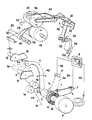
- A preferred embodiment of the device of the present invention is described hereinafter by way of non-limiting example with reference to the single accompanying drawing figure.
- This is a diagrammatic isometric view of the intermittent storage and release device of the present invention cooperating with the yarn guide element, the bobbin under formation being driven by the friction band of the drive roller, the figure showing the moment of maximum storage in the yarn travel while the yarn guide element is moving in the increasing diameter direction of the cross-wound bobbin.
- A connection pin 1 is rigidly fixed to a swinging
arm 2. 1 a is the position which the pin 1 assumes at the other end of its swing movement. Themobile arm 2 forms part of the yarn compensation and release lever system, which operates as the linear position element of a system for controlling and monitoring the yarn storage. 2a is the position which themobile arm 2 assumes at that moment during its swing movement when the stored length of theyarn 18 is zero or a minimum. A bush orring 3 rigidly joins together one end of themobile arm 2 and one end of a second swingingarm 4 of the yarn storage and release lever system. Themobile arm 4 of the yarn compensation and release lever system operates as the actual storage and release element for theyarn 18 while also acting as the tension compensation and adjustment element for theyarn 18 being wound. 4a is the position which themobile arm 4 assumes at that moment during its swing movement when the stored yarn length is zero or a minimum. A mobile yarn deflecting and guide roller 5 is carried by the free end of themobile arm 4 but is able to rotate about its own axis so as not to generate grazing friction against the yarn undergoing continuous collection. The roller 5 has a substantially cylindrical profile, 5a is the position which the mobile yarn deflecting and guide roller 5 assumes at that moment during its swing movement when the stored yarn length is zero or a minimum. A spiralelastic element 6 has an end connected to the pin 1 and stores drive energy by means of appropriate deformation resulting from the angular rotation applied by ashaft 10 which is connected to the other end of theelastic element 6. This element consists of a steel strip or wire or similar steel element, wound substantially as a flat Archimedes spiral. Sensing means in form of twoposition transducers 7 and 17 of optical, magnetic analog or digital type sense the yarn storage degree at the yarn storage and release means defined by elements 1-6, and convert the angular position of the end of themobile arm 2 into an electrical signal or a series of electrical signals as a function of the yarn storage degree. Acontrol unit 8 which comprises an electrial comparator and an electronic microprocessor receives and processes the signals originating from thetransducers 7 and 17, to then activate adrive source 9 for regularizing the storage ofyarn 18. Thedrive source 9 operates theshaft 10 to be rotated angularly so as to vary the preloading of the spiralelastic element 6 for the purpose of regularizing the storage if this has strayed outside the range of preset values. Theshaft 10 is fixed or hinged, at or in proximity to its end, to the inner end of the spiralelastic preloading element 6. A yarn deflecting and guideroller 11 having a substantially cylindrical profile is connected to abase plate 13 and is free to rotate about its own axis in order not to generate grazing friction against theyarn 18 undergoing continuous collection movement. A yarn deflecting and guideroller 12 of substantially cylindrical profile is connected to abase plate 15 and is free to rotate about its own axis. Thebase plate 13 for theroller 11 is fixed to the machine structure, not shown on the figure. Thebase plate 15 for theroller 12 is also fixed to the machine structure. A pair ofrollers yarn 18 are pressed against each other with saidyarn 18 passing between then to withdraw it at constant speed from a spinning unit of a rotor spinning machine and feed it towards the compensator device of the present invention. A solid orhollow shaft 20 of substantially circular cross-section is operated as a control rod for ayarn guide element 26 by means of a suitably shaped cam so as to transmit a reciprocating movement of suitable kinematic and dynamic characteristics to theyarn guide element 26. Adrive roller 22 rotates theconical bobbin 24 under formation at afriction region 28 in the form of a narrow circular band. The drive shaft orrod 20 extends along the entire operational winding face of the machine. A blade 30 serves for deflecting the path of theyarn 18. - Said blade 30 can be linear or shaped with more or less accentuated profiles already known in the art. A
bobbin carrier arm 34 rototably supports theyarn bobbin 24.Connection cables transducers 7 and 17 with thecontrol unit 8. - A
connection cable 40 connects thecontrol unit 8 with thedrive source 9. 42 indicates the swing path of themobile arm shaft 20. A shaft or pivot 46 coaxial with thebush 3 defines the swinging axis about which the yarn storage and intermittent release lever system swings by way of thebush 3. Adrive shaft 48 extends along the entire winding face of the machine and rigidly supports thedrive roller 22. Abidirectional drive unit 50 preferably consisting of a stepping motor inclines the axis of rotation of theconical bobbin 24 in one direction or the other in order to vary the line of effective contact between thebobbin 24 and thedrive roller 22 to consequently obtain a controlled variation in the winding speed of theyarn 18. - A
pivot 52 defines the axis about which thebobbin carrier arm 34 rotates by virtue of the rotary movement of thebidirectional drive unit 50. - A
cam 53 is keyed onto the output shaft of thedrive unit 50, the rotation of which determines the angular displacement of alever 54, rotatably mounted on thepivot 52, and consequently the variation in the inclination of thebobbin carrier arm 34. 56 is the line representing the inclination of the axis of rotation of theconical bobbin 24 to a substantially vertical plane containing the axis of thedrive roller 22. Aconnection cable 58 connects thecontrol unit 8 with the drive source of thebidirectional drive unit 50. 60 is the line representing the angular rotation in both directions of thepivot 52. Atransverse hub 33 rigidly connects thelever 54 and thebobbin carrier arm 34. - The operation of the device according to the invention is as follows.
- The purpose of the storage and release device for the
yarn 18 being wound onto theconical bobbin 24 is to adapt the varying winding speed deriving from the taper of thebobbin 24 to the constant outlet speed from thefeed rollers yard 18 is being collected on the minor diameter of thebobbin 24 the winding speed is less than the feed speed from the extractingrollers mobile arm 4 stores a suitable length ofyarn 18. This stored length is released gradually as the collection speed increases on moving the yarn towards the major diameter of thebobbin 24 by means of theyarn guide element 26. - The ratio of the minor diameter to the major diameter of the
bobbin 24 under formation determines the maximum length ofyarn 18 which has to be stored and then released for each complete cycle of theyarn guide element 26. - As said ratio decreases continuously with increasing fullness of the
bobbin 24 under formation, the amplitude of the swing movement of the mobile yarn deflecting and guide roller 5 also decreases for decreasing storage of theyarn 18. - The mobile deflecting roller 5 generates a loop by deflecting the
yarn 18 from its path. This loop therefore has a continuously varying amplitude and the device of the present invention is automatically controlled in accordance with this variation, to act as a compensator for the periodic tension variations which arise as a result of the periodic winding speed variations in the formation of the conical bobbin. - In order to compensate said tension variations to which the collected
yarn 18 is subjected and level them out to a substantially constant value, the mobile deflecting roller 5, which drags the yarn into a temporary storage loop by means of the swing movement of themobile arm 4 under the effect of theelastic preloading element 6 which provides a force opposing and balancing the tension force produced by theyarn 18 on thearm 4, has to assume different positions relative to the fixed deflectingrollers - These latter deflecting rollers, besides being rotatable about themselves, must provide precise guiding of the
yarn 18 by virtue of their shape. - Because of the rigid connection between the two
mobile arms arm 2. - Said end interacts with the
linear position transducers 7 and 17 without the need for mutual contact, these latter generating at their output a signal or several signals of electrical nature which are fed through theconnection cables control unit 8 which compares said signals with at least one reference signal defining a range of swing within which a predetermined yarn storage is obtained. If during the continuous winding process the storage swing end positions remain within the predetermined limits preset by the position of the twotransducers 7 and 17, thecontrol unit 8 confirms that the storage and release cycles of theyarn 18 are regular. Thus no output signal is generated at the output of thecontrol unit 8 and no activation signal is therefore fed to thedrive source 9. If during the continuous winding process the storage swing strays beyond or outside the predetermined preset limits, the corresponding mobile linear position of the end of thearm 2 is such as to cause thetransducers 7 and 17 to generate an electrical signal or signals which after suitable comparison in thecontrol unit 8 result to be outside the regular range of swing defined by said reference signal(s), and this gives instant rise to an output signal which activates thedrive source 9. This latter angularly rotates theshaft 10 to increase or decrease the preloading of the spiralelastic element 6 in order to adjust the swinging lever system to swing within the regular swing range and to so return the storage to within the limits of the preset storage degree or range. - This latter operation can be further clarified as follows. If the mobile deflecting roller 5 causes the loop in the
yarn 18 to assume a position which exceeds the maximum storage limit allowed by the range of swing predetermined for regular operation, thedrive source 9 is operated and rotates theshaft 10 angularly in the direction which slightly reduces the amount of preloading of the spiralelastic element 6. This latter element therefore slackens and compels the yarn, by means of thelever system yarn 18 being continuously wound must be sufficiently gradual to prevent the formation of knots, tangles or similar defects which if collected on the bobbin would reduce its quality. - By only slightly decreasing the average tension of the yarn being wound, the yarn slackens and becomes less inserted into the already deposited layers of yarn, and therefore proceeds to wind in the form of turns having a slightly greater diameter.
- These turns rapidly and progressively take up the excessive storage created by a multiplicity of factors.
- If the mobile deflecting roller 5 causes the loop in the
yarn 18 to assume a position below the minimum storage limit allowed by the range of swing predetermined for regular operation, thedrive source 9 is operated and rotates theshaft 10 angularly in the direction which slightly increases the amount of preloading of the spiralelastic element 6. This latter element therefore tightens and compels the yarn, by means of thelever system conical bobbin 24 under an average tension which is slightly higher than the preceding situation. This increase in the average tension of theyarn 18 being continuously wound can be substantially rapid as there is no danger of forming knots, tangles or similar defects. By only slightly increasing the average tension of the yarn being wound, the yarn tightens and becomes more inserted into the already deposited layers of yarn, and therefore proceeds to wind as turns having a slightly smaller diameter. Such turns rapidly and progressively cause the yarn to store in the form of an increasingly larger loop, with the result that the intermittent swing of themobile arm 4 again falls within the limits of the range of swing for regular operation. - It is well known that the yarn tension can only be allowed to fluctuate within a fairly narrow range. On the one hand, the yarn tension must not assume such values as to compromise the integrity and elasticity of the yarn itself, and on the other hand must not fall below values which allow the formation of twists or knots or similar entanglement defects. The yarn storage and release lever system must obviously operate within the range of regular tension values, ie those which do not lead to the aforementioned drawbacks.
- As is apparent from the aforesaid, the swing movement of the storage lever system subjected to the action of the spiral
elastic element 6 may be insufficient or only partly sufficient to restore the intermittent swing within the range corresponding to regular storage. To ensure that even in such cases regular swing motion is restored, thebidirectional drive unit 50 is operated after a sufficiently short time in order to incline the axis of theconical bobbin 24 relative to the axis of thebobbin drive roller 22 so as to vary the average winding speed. - If non-regular storage swings still persist immediately after the spiral
elastic element 6 has reached its upper or lower preloading limit, thecontrol unit 8 immediately emits an electrical control signal which activates thebidirectional drive unit 50. - The aforesaid limits to the preloading of the
elastic element 6 are related to the limiting tensioning and slackening values allowed by the technical characteristics of the type of yarn being wound. - On receiving the activation signal, the
bidirectional drive unit 50 rotates thecam 53 which, by way of thelever 54 pivoted on thepivot 52, transmits an angular rotation to thebobbin carrier arm 34 to incline the axis of rotation of theconical bobbin 24 in one direction or the other relative to the axis of thebobbin drive roller 22, and consequently displace the diameter of effective contact between theconical bobbin 24 and driveroller 22 to obtain a suitable variation in the average winding speed of theyarn 18 in order to restore the storage swing to within the range of values corresponding to regular storage. - This latter operation can be further clarified as follows. If the mobile deflecting roller 5 causes the loop in the
yarn 18 to assume a position which exceeds the maximum preset storage limit, the position of themobile arm 2 causes the transducer 7 to generate an electrical output signal corresponding to said position. - Said electrical output signal is fed to the
control unit 8 through theconnection cable 39. - The
control unit 8, after identifying the type of electrical signal received from the transducer 7, correspondingly produces at its output a specific electrical control signal, which is fed through theconnection cable 58 to activate thebidirectional drive unit 50. Said unit transmits an angular anticlockwise rotation to thebobbin carrier arm 34, which consequently displaces the diameter of effective contact between theconical bobbin 24 and thedrive roller 22 in the decreasing diameter direction, ie towards the minor base of the bobbin. - Thus the average winding speed increases, ie settles at an average value which is slightly higher than the previous average value, so causing rapid and progressive takeup of the excessive storage created by a multiplicity of factors.
- As the layer of yarn present on the conical base tube on which the yarn winds is sufficiently soft and therefore deformable, this displacement of the contact diameter or band takes place gradually as allowed by the
drive unit 50. If the mobile deflecting roller 5 causes the storage loop in theyarn 18 to assume a position which lies below the preset minimum storage limit, the position of themobile arm 2 causes thetransducer 17 to generate an electrical output signal of value corresponding to said position. - Said electrical output signal from the
transducer 17 is fed to thecontrol unit 8 through theconnection cable 38. - The
control unit 8, after identifying the type of electrical signal received from thetransducer 17, correspondingly produces at its output a specific electrical control signal, which is fed through theconnection cable 58 to activate thebidirectional drive unit 50. Said unit transmits on angular clockwise rotation to thebobbin carrier arm 34, which consequently displaces the diameter or band of effective contact between theconical bobbin 24 and thedrive roller 22 in the increasing diameter direction, ie towards the major base of theconical bobbin 24. Thus the average winding speed decreases, ie settles at an average value which is slightly lower than the previous average value, so causing the yarn to be progressively stored in a loop of continuously increasing size, with the result that the intermittent swing of themobile arm 4 is restored to within the predetermined regular range preset by the positions assumed by themobile arm 2. - The width of said regular range is predetermined by the geometrical characteristics of the winding being made together with the characteristics of the yarn and
conical bobbin 24 under formation. - It has been found that the device for intermittently storing and releasing yarn during the winding of conical bobbins fed with yarn at constant speed operates very reliably, and periodically compensates the variations in yarn tension without the mobile deflecting roller 5 undergoing uncontrollable swings. As is apparent from the foregoing, the swinging lever system is swingable independently of the reciprocating movement of the
yarn distributing element 26 associated to thebobbin 24. - The use of the device according to the invention is not limited to the winding of conical bobbins produced on spinning units, but can also be advantageously applied to the winding of conical bobbins or packages on other winding units.
- A preferred embodiment has been described herein but it is apparent that other embodiments are possible which fall within the scope of the appendant claims.
- Thus the positions of the operating lever systems can vary; different drive arrangements can be provided; it is also possible to vary the shapes and dimensions of the yarn deflecting-storage roller 5 together with the
arms - The
bidirectional drive unit 50 for inclining thebobbin carrier arm 34 can consist of pneumatic or electromagnetic actuators or electric motors (like stepping motors), which can act either by directly rotating thearm 34 or by rotating specific cams and lever systems in the two directions.
Claims (4)
characterised in that
Applications Claiming Priority (2)
| Application Number | Priority Date | Filing Date | Title |
|---|---|---|---|
| IT19762/87A IT1203385B (en) | 1987-03-19 | 1987-03-19 | DEVICE AND RELATED PROCEDURE FOR ACUMMULATING AND RETURNING INTERMITTENT WIRE IN THE WINDING OF CONICAL SPOOLS FEED WITH CONSTANT SPEED WIRE |
| IT1976287 | 1987-03-19 |
Publications (2)
| Publication Number | Publication Date |
|---|---|
| EP0285204A1 EP0285204A1 (en) | 1988-10-05 |
| EP0285204B1 true EP0285204B1 (en) | 1992-07-08 |
Family
ID=11161018
Family Applications (1)
| Application Number | Title | Priority Date | Filing Date |
|---|---|---|---|
| EP88200490A Expired EP0285204B1 (en) | 1987-03-19 | 1988-03-17 | Device and relative method for intermittently storing and returning yarn during the winding of conical bobbins fed with yarn at constant speed |
Country Status (5)
| Country | Link |
|---|---|
| US (1) | US4854511A (en) |
| EP (1) | EP0285204B1 (en) |
| CS (1) | CS277423B6 (en) |
| DE (1) | DE3872557T2 (en) |
| IT (1) | IT1203385B (en) |
Cited By (1)
| Publication number | Priority date | Publication date | Assignee | Title |
|---|---|---|---|---|
| DE10062459A1 (en) * | 2000-12-14 | 2002-06-20 | Schlafhorst & Co W | Bobbin winder has a computer to set the bobbin frame, before winding, to the required angle for the bobbin sleeve to give cylindrical or conical cross wound bobbins |
Families Citing this family (12)
| Publication number | Priority date | Publication date | Assignee | Title |
|---|---|---|---|---|
| US5092534A (en) * | 1990-11-15 | 1992-03-03 | Tanaka Seiki Co., Ltd. | Tensioning apparatus |
| US5791583A (en) * | 1995-02-06 | 1998-08-11 | Alexander Machinery, Inc. | Cloth takeup control apparatus and method |
| BE1009578A3 (en) * | 1995-09-18 | 1997-05-06 | Usines Textiles Ernaelsteen | Method and device for processing and winding yarn |
| AU6270698A (en) | 1997-02-05 | 1998-08-25 | Plant Engineering Consultants, Inc. | Precision winding method and apparatus |
| ITMI20010425A1 (en) | 2001-03-01 | 2002-09-01 | Savio Macchine Tessili Spa | YARN COLLECTION DEVICE ON TAPERED SPOOLS WITH COMPENSATION OF THE SPEED RECALL SPEEDS |
| EP2204481B1 (en) * | 2008-12-30 | 2013-07-10 | L.G.L. Electronics S.p.A. | Positive yarn feeder with tension limiter |
| CN103569787B (en) * | 2013-09-29 | 2015-03-25 | 萧振林 | Tensile Stress Control System and Control Method for Fabric Winding |
| CN106032218B (en) * | 2015-03-20 | 2017-11-17 | 成都瑞克西自动化技术有限公司 | The tape handler of double bar straps can be batched |
| ITUA20162665A1 (en) * | 2016-04-18 | 2017-10-18 | Giovanni Corsani | YARN FEEDER FOR TEXTILE MACHINES WITH AUTOMATIC VOLTAGE REGULATION |
| CZ2017302A3 (en) * | 2017-05-29 | 2018-12-12 | Rieter Cz S.R.O. | An electromagnetically active yarn loop compensator at the working site of a textile machine and methods of its control |
| CN111942965B (en) * | 2020-08-11 | 2022-02-22 | 西安交通大学 | Swing rod type segmented small-tension conveying method and device for carbon fiber prepreg tows |
| CN112850363B (en) * | 2021-01-22 | 2022-02-22 | 北京航空航天大学 | Variable-rod-length rigid-flexible coupling mechanism for regulating and controlling tension of fiber bundle |
Family Cites Families (14)
| Publication number | Priority date | Publication date | Assignee | Title |
|---|---|---|---|---|
| US2102109A (en) * | 1934-12-28 | 1937-12-14 | American Bemberg Corp | Tension compensator for winding machines |
| US3300161A (en) * | 1963-09-21 | 1967-01-24 | Frau Sigrid Heim | Control device |
| DE1785153C3 (en) * | 1968-08-16 | 1978-06-22 | Reiners, Walter, Dr.-Ing., 4050 Moenchengladbach | Device for balancing the thread tension on winding devices |
| IT1052316B (en) * | 1974-11-20 | 1981-06-20 | Schlafhorst & Co W | DEVICE AND PROCEDURE FOR WINDING CONICAL SPOOLS WITH CROSSED WINDING AT CONSTANT SPEED OF YARN ADDUCTION |
| DE2454916C2 (en) * | 1974-11-20 | 1983-10-20 | W. Schlafhorst & Co, 4050 Mönchengladbach | Method and device for winding conical cheese at a constant thread feed speed |
| DE2513981A1 (en) * | 1975-03-29 | 1976-10-07 | Schlafhorst & Co W | METHOD AND DEVICE FOR CONTROLLING AND / OR REGULATING THE THREAD TENSION WHEN WINDING A TEXTILE SPOOL |
| US4019691A (en) * | 1975-11-10 | 1977-04-26 | Centralny Osrodek Badawxzorozwojowy Maszyn Wlokienniczych "Centamatex" | Method and apparatus for winding yarn onto a cross-and-cone wound bobbin |
| FR2337094A1 (en) * | 1975-11-20 | 1977-07-29 | Babcock Wire Equipment | Wire spooling machine control system - includes pulse circuit controlling dancer arm and reciprocating distributor wheel for constant wire tension |
| DE2721972C3 (en) * | 1977-05-14 | 1979-12-06 | Barmag Barmer Maschinenfabrik Ag, 5630 Remscheid | Winding device for threads |
| US4133493A (en) * | 1978-04-03 | 1979-01-09 | Barber-Colman Company | Self-threading tension compensator |
| NL7812156A (en) * | 1978-12-14 | 1980-06-17 | Hollandse Signaalapparaten Bv | A method for subtracting a yarn wrapped around a yarn and winding it up into a yarn package and device for carrying out this method. |
| US4312482A (en) * | 1979-09-24 | 1982-01-26 | Barber-Colman Company | Auto-loading tension compensator |
| GB2125072B (en) * | 1982-08-07 | 1986-08-13 | Geoffrey Edmund Whellams | Self-adjusting filament tensioner |
| DE8527472U1 (en) * | 1985-09-26 | 1985-11-14 | Neumünstersche Maschinen- und Apparatebau GmbH (Neumag), 2350 Neumünster | Thread tension regulator |
-
1987
- 1987-03-19 IT IT19762/87A patent/IT1203385B/en active
-
1988
- 1988-03-17 DE DE8888200490T patent/DE3872557T2/en not_active Expired - Lifetime
- 1988-03-17 EP EP88200490A patent/EP0285204B1/en not_active Expired
- 1988-03-18 US US07/170,279 patent/US4854511A/en not_active Expired - Lifetime
- 1988-03-18 CS CS881797A patent/CS277423B6/en not_active IP Right Cessation
Cited By (1)
| Publication number | Priority date | Publication date | Assignee | Title |
|---|---|---|---|---|
| DE10062459A1 (en) * | 2000-12-14 | 2002-06-20 | Schlafhorst & Co W | Bobbin winder has a computer to set the bobbin frame, before winding, to the required angle for the bobbin sleeve to give cylindrical or conical cross wound bobbins |
Also Published As
| Publication number | Publication date |
|---|---|
| EP0285204A1 (en) | 1988-10-05 |
| IT8719762A0 (en) | 1987-03-19 |
| DE3872557D1 (en) | 1992-08-13 |
| CS179788A3 (en) | 1992-08-12 |
| US4854511A (en) | 1989-08-08 |
| CS277423B6 (en) | 1993-03-17 |
| IT1203385B (en) | 1989-02-15 |
| DE3872557T2 (en) | 1992-12-10 |
Similar Documents
| Publication | Publication Date | Title |
|---|---|---|
| US4854511A (en) | Device and method for intermittently storing and returning yarn during the winding of conical bobbins fed with yarn at constant speed | |
| US5029762A (en) | Yarn winding apparatus and method | |
| US6490762B1 (en) | Winding device | |
| US4548366A (en) | Chuck drive system | |
| EP0284144B1 (en) | Device and method for intermittently storing and returning yarn during the winding of conical bobbins fed with yarn at constant speed | |
| JP2000034060A (en) | Method and device for taking up thread on conical spool | |
| US3730448A (en) | Winding machines with pivotable rail-guided toggle traversing rod guides | |
| EP0630846B1 (en) | Method and apparatus for distributing wound yarn on a bobbin driven by a grooved roller | |
| RU2339564C2 (en) | Bobbin-winding device | |
| US4789107A (en) | Process and apparatus for winding a thread supplied at a constant speed onto a cross wound bobbin | |
| US5100072A (en) | Yarn winding apparatus and method | |
| EP1900670A1 (en) | Improved winding process of yarn on packages with individual thread guide devices | |
| EP0516696B1 (en) | A guiding device for a machine for winding wire-like goods | |
| JP7181947B2 (en) | Method, improved yarn feeding system and apparatus for optimal yarn feeding to textile machines operating in highly discontinuous or staggered motion | |
| EP0351002B1 (en) | Device for regulating the yarn windings speed in the formation of conical bobbins in a rotor spinning machine | |
| US4854512A (en) | Method and device for intermittently storing and returning yarn during the winding of conical bobbins fed with yarn at constant speed | |
| CS195300B2 (en) | Method of winding up the conical,crossly spooled bobbins at constant speed of the yarn feed and facility for executing the same | |
| US3945579A (en) | Winding mechanisms with friction drive rollers | |
| US4854510A (en) | Device and method for storing and returning yarn during the winding of conical bobbins fed with yarn at constant speed | |
| EP0378870A1 (en) | Tensioning device with adjustable action for adjusting the tension of threads fed to textile machines, in particular to knitting machines | |
| US4854514A (en) | Device and method for storing and returning yarn during the winding of conical bobbins fed with yarn at constant speed | |
| US4858837A (en) | Device and method for intermittently storing and returning yarn during the winding of conical bobbins fed with yarn at constant speed | |
| US4854509A (en) | Method and device for intermittently storing and returning yarn during the winding of conical bobbins fed with yarn at constant speed | |
| CN1008193B (en) | Open end spinner piecing method and apparatus and multi-position friction spinner embodying same | |
| EP0284147A1 (en) | Device for intermittently storing and returning yarn during the winding of conical bobbins fed with yarn at constant speed, and the relative method |
Legal Events
| Date | Code | Title | Description |
|---|---|---|---|
| PUAI | Public reference made under article 153(3) epc to a published international application that has entered the european phase |
Free format text: ORIGINAL CODE: 0009012 |
|
| AK | Designated contracting states |
Kind code of ref document: A1 Designated state(s): CH DE FR GB LI |
|
| 17P | Request for examination filed |
Effective date: 19890223 |
|
| 17Q | First examination report despatched |
Effective date: 19900806 |
|
| GRAA | (expected) grant |
Free format text: ORIGINAL CODE: 0009210 |
|
| AK | Designated contracting states |
Kind code of ref document: B1 Designated state(s): CH DE FR GB LI |
|
| ET | Fr: translation filed | ||
| REF | Corresponds to: |
Ref document number: 3872557 Country of ref document: DE Date of ref document: 19920813 |
|
| PLBE | No opposition filed within time limit |
Free format text: ORIGINAL CODE: 0009261 |
|
| STAA | Information on the status of an ep patent application or granted ep patent |
Free format text: STATUS: NO OPPOSITION FILED WITHIN TIME LIMIT |
|
| 26N | No opposition filed | ||
| PGFP | Annual fee paid to national office [announced via postgrant information from national office to epo] |
Ref country code: FR Payment date: 19990309 Year of fee payment: 12 |
|
| PGFP | Annual fee paid to national office [announced via postgrant information from national office to epo] |
Ref country code: GB Payment date: 19990318 Year of fee payment: 12 |
|
| REG | Reference to a national code |
Ref country code: CH Ref legal event code: PUE Owner name: SAVIO S.P.A. TRANSFER- SAVIO MACCHINE TESSILI S.P. |
|
| REG | Reference to a national code |
Ref country code: FR Ref legal event code: TP |
|
| PG25 | Lapsed in a contracting state [announced via postgrant information from national office to epo] |
Ref country code: GB Free format text: LAPSE BECAUSE OF NON-PAYMENT OF DUE FEES Effective date: 20000317 |
|
| GBPC | Gb: european patent ceased through non-payment of renewal fee |
Effective date: 20000317 |
|
| PG25 | Lapsed in a contracting state [announced via postgrant information from national office to epo] |
Ref country code: FR Free format text: LAPSE BECAUSE OF NON-PAYMENT OF DUE FEES Effective date: 20001130 |
|
| REG | Reference to a national code |
Ref country code: FR Ref legal event code: ST |
|
| PGFP | Annual fee paid to national office [announced via postgrant information from national office to epo] |
Ref country code: CH Payment date: 20040317 Year of fee payment: 17 |
|
| PGFP | Annual fee paid to national office [announced via postgrant information from national office to epo] |
Ref country code: DE Payment date: 20040325 Year of fee payment: 17 |
|
| PG25 | Lapsed in a contracting state [announced via postgrant information from national office to epo] |
Ref country code: LI Free format text: LAPSE BECAUSE OF NON-PAYMENT OF DUE FEES Effective date: 20050331 Ref country code: CH Free format text: LAPSE BECAUSE OF NON-PAYMENT OF DUE FEES Effective date: 20050331 |
|
| PG25 | Lapsed in a contracting state [announced via postgrant information from national office to epo] |
Ref country code: DE Free format text: LAPSE BECAUSE OF NON-PAYMENT OF DUE FEES Effective date: 20051001 |
|
| REG | Reference to a national code |
Ref country code: CH Ref legal event code: PL |