EP0285007A1 - Watercraft featuring a built-in water vibration damping system - Google Patents
Watercraft featuring a built-in water vibration damping system Download PDFInfo
- Publication number
- EP0285007A1 EP0285007A1 EP88104771A EP88104771A EP0285007A1 EP 0285007 A1 EP0285007 A1 EP 0285007A1 EP 88104771 A EP88104771 A EP 88104771A EP 88104771 A EP88104771 A EP 88104771A EP 0285007 A1 EP0285007 A1 EP 0285007A1
- Authority
- EP
- European Patent Office
- Prior art keywords
- shell
- watercraft
- fact
- skid
- float
- Prior art date
- Legal status (The legal status is an assumption and is not a legal conclusion. Google has not performed a legal analysis and makes no representation as to the accuracy of the status listed.)
- Withdrawn
Links
Images


Classifications
-
- B—PERFORMING OPERATIONS; TRANSPORTING
- B63—SHIPS OR OTHER WATERBORNE VESSELS; RELATED EQUIPMENT
- B63B—SHIPS OR OTHER WATERBORNE VESSELS; EQUIPMENT FOR SHIPPING
- B63B1/00—Hydrodynamic or hydrostatic features of hulls or of hydrofoils
- B63B1/16—Hydrodynamic or hydrostatic features of hulls or of hydrofoils deriving additional lift from hydrodynamic forces
- B63B1/18—Hydrodynamic or hydrostatic features of hulls or of hydrofoils deriving additional lift from hydrodynamic forces of hydroplane type
- B63B1/22—Hydrodynamic or hydrostatic features of hulls or of hydrofoils deriving additional lift from hydrodynamic forces of hydroplane type with adjustable planing surfaces
Definitions
- the present invention relates to a watercraft featuring a built-in water vibration damping system.
- the present invention relates to a watercraft, preferably of the glider type, having streamlined surfaces which, normally immersed when the craft is stationary, provide for producing a load-bearing effect for raising the said surfaces into contact with the surface of the water, when the craft is operated in excess of a given predetermined speed.
- a major drawback in the design of watercraft in general, and the aforementioned type in particular, is that, due to the singularities of the water surface and the rigidity of the hull, forces and moments are transmitted by the water to the wetted surface of the hull, which forces and moments may result in a sharp change in trim, if not complete detachment of the hull from the surface of the water.
- the aim of the present invention is to provide a watercraft of the aforementioned type designed to substantial strictlyly overcome the aforementioned drawback.
- a watercraft preferably of the glider type, characterised by the fact that it comprises an "unsuspended” portion designed to contact the water, and a “suspended” portion preferably connected to at least a drive assembly and preferably comprising at least a single-passenger compartment; the said "suspended” and “unsuspended” portions being connected via the interposition of a device for damping the vibration transmitted, in use, between the water and the said "unsuspended” portion.
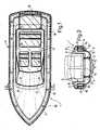
- Number 1 in Fig.s 1 and 2 indicates a watercraft comprising an outer shell 2 having streamlined bottom surfaces 3 designed to glide over and in contact with the surface of the water; and an inner shell 4 having an upper passenger compartment 5 and a rear engine compartment 6.
- the said outer shell 2 presents a peripheral outer flange 7 extending outwards from the top edge of shell 2.
- the said inner shell 4 presents, along its top edge, a peripheral outer flange 8 located over flange 7 and the free peripheral end of which blends with the top end of a dummy outer side panel 9 surrounding the outside of flange 7.
- Dummy side panel 9 extends downwards from flange 8 and presents, on its bottom edge, an inner flange 10 underneath flange 7 and facing both flanges 7 and 8.
- a damping device 11 comprising a first number of springs 12 or similar damping elements located between bottom wall 13 of shell 4 and opposite bottom wall 15 of shell 2; and a second number of springs or similar damping elements 16 located between flanges 8 and 10.
- outer shell 2 constitutes an "unsuspended" mass subjected to all the long- and short-wave vibration transmitted, in use, by contact with the surface of the water; whereas shell 4 constitutes a "suspended” mass subjected only to long-wave oscillation, if any.
- damping device 11 prevents any transmission to inner shell 4 of the vibration imparted on outer shell 2 by the water surface over which craft 1 is traveling, thus preventing any vertical inertial movement which, by affecting the position of both the drive assembly and passenger compartment 5 in relation to the surface of the water, would otherwise result in discomfort to passengers, and possibly also affect the speed of the drive assembly, with consequent overconsumption and damage to drive line components and propellers.
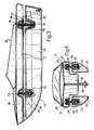
- the Fig.3 and 4 embodiment relates to a watercraft 17 comprising an upper shell 18 having a passenger compartment 19 and housing an aft drive assembly 20.
- Shell 18 presents two lateral wings 21 beneath each of which is provided a float or skid 22 having streamlined surfaces 23.
- Each skid 22 is connected to the respective wing 21 via the interposition of a damping device 24 comprising a front damper 25 with a respective coaxial damping spring 26, and a rear damper 27 with a respective coaxial damping spring 28.
- each front damper 25 is secured by its base to respective skid 22, and is connected to respective wing 21 via a cylindrical hinge 29 arranged crosswise in relation to the axis of craft 17.
- Each rear damper 27, on the other hand, is connected to respective skid 22 and respective wing 21 via cylindrical hinges 30 and 31 parallel with hinge 29.
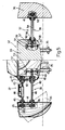
- the Fig.5 and 6 embodiment relates to a watercraft 32 comprising an intermediate shell 33 having a passenger compartment 34 and housing two aft drive assemblies 35. On opposite sides of intermediate shell 33 there are provided two floats or skids 36, each connected to shell 33 via a respective damping device 37.
- each damping device 37 comprises a front suspension 38 and a rear suspension 39.
- Each front suspension 38 comprises an articulated parallelogram 40 lying in a substantially vertical plane and, in turn, comprising two substantially vertical bars 41 and 42 respectively integral with skid 36 and intermediate shell 33, and two superimposed rods 43 and 44 arranged substantially horizontally and the end of which are connected to bar 41 and 42 via spherical hinges 45.
- upper rod 43 consists of two portions 46 and 47 connected by a dual-acting hydraulic damper 48 which, in addition to absorbing axial stress on rod 43, enables the length of rod 43 to be adjusted so as to adjust the position of respective skid 36 and gradually increase the wetted surface of the same as speed is reduced.
- Lower rod 44 extends inside shell 33 and beyond respective hinge 45 in the form of an integral arm 49, which is located between a top and bottom longitudinal structural element 51 and 50 of shell 33, and is connected to the said opposed structural elements 50 and 51 by means of two spring systems 52 and 53.
- Each rear suspension 39 comprises a substantially horizon tal rod 54 extending between the said bars 41 and 42 and connected to the same by means of a spherical hinge 55 and a cylindrical longitudinal hinge 56 respectively.
- Rod 54 extends inside shell 33 and beyond respective hinge 56 in the form of an integral arm 57 located between structural elements 50 and 51 of shell 33 and connected to the same by means of two spring systems 58 and 59.
- Suspensions 38 and 39 thus enable each skid 36 to adjust its position in relation to shell 33 about both the longitudinal axis of hinge 56 and the axis of respective rod 54, and are especially effective when applied to a competition craft.
- the Fig.7 embodiment relates to a hydrofoil boat 60, the center shell 61 of which presents a passenger compartment and is connected to two front side skids 62 and a rear skid 63 by means of respective struts 64, each comprising a tubular bottom rod 65 and a top rod 66 connected telescopically. Telescopic slide of each rod 66 and respective rod 65 is regulated by a respective damping device 67 comprising a spring 68.
Abstract
A watercraft, preferably of the glider type, presenting an "unsuspended" portion with streamlined surfaces for gliding over the surface of the water, and a "suspended" portion normally featuring at least a single-passenger compartment and connected to the "unsuspended" portion via the interposition of a device for damping vibration transmitted by the water in contact with the aforementioned "unsuspended" portion.
Description
- The present invention relates to a watercraft featuring a built-in water vibration damping system.
- In particular, the present invention relates to a watercraft, preferably of the glider type, having streamlined surfaces which, normally immersed when the craft is stationary, provide for producing a load-bearing effect for raising the said surfaces into contact with the surface of the water, when the craft is operated in excess of a given predetermined speed.
- A major drawback in the design of watercraft in general, and the aforementioned type in particular, is that, due to the singularities of the water surface and the rigidity of the hull, forces and moments are transmitted by the water to the wetted surface of the hull, which forces and moments may result in a sharp change in trim, if not complete detachment of the hull from the surface of the water.
- This invariably results, not only in "rough" sailing, but, more importantly, in wasted power potential and possible damage to the drive and/or propeller assemblies.
- The aim of the present invention is to provide a watercraft of the aforementioned type designed to substantially overcome the aforementioned drawback.
- With this aim in view, according to the present invention, there is provided a watercraft, preferably of the glider type, characterised by the fact that it comprises an "unsuspended" portion designed to contact the water, and a "suspended" portion preferably connected to at least a drive assembly and preferably comprising at least a single-passenger compartment; the said "suspended" and "unsuspended" portions being connected via the interposition of a device for damping the vibration transmitted, in use, between the water and the said "unsuspended" portion.
- A number of non-limiting embodiments of the present invention will be described by way of examples with reference to the accompanying drawings, in which :
- Fig.1 shows a plan view of a first embodiment of the watercraft according to the present invention;
- Fig.2 shows a section along line II-II of Fig.1;
- Fig.3 shows a partially-sectioned side view of a second embodiment of the watercraft according to the present invention;
- Fig.4 shows a front view of the Fig.3 watercraft;
- Fig.5 shows a partially-sectioned front view, with parts removed for simplicity, of a third embodiment of the watercraft according to the present invention;
- Fig.6 shows a partially-sectioned, partial plan view of the Fig.5 watercraft;
- Fig.7 shows a front view of a fourth embodiment of the watercraft according to the present invention.
-
Number 1 in Fig.s 1 and 2 indicates a watercraft comprising anouter shell 2 havingstreamlined bottom surfaces 3 designed to glide over and in contact with the surface of the water; and aninner shell 4 having an upper passenger compartment 5 and arear engine compartment 6. - As shown in Fig.2, the said
outer shell 2 presents a peripheral outer flange 7 extending outwards from the top edge ofshell 2. Similarly, the saidinner shell 4 presents, along its top edge, a peripheralouter flange 8 located over flange 7 and the free peripheral end of which blends with the top end of a dummy outer side panel 9 surrounding the outside of flange 7. Dummy side panel 9 extends downwards fromflange 8 and presents, on its bottom edge, aninner flange 10 underneath flange 7 and facing bothflanges 7 and 8. - Between
shells damping device 11 comprising a first number ofsprings 12 or similar damping elements located betweenbottom wall 13 ofshell 4 andopposite bottom wall 15 ofshell 2; and a second number of springs orsimilar damping elements 16 located betweenflanges - Thus,
outer shell 2 constitutes an "unsuspended" mass subjected to all the long- and short-wave vibration transmitted, in use, by contact with the surface of the water; whereasshell 4 constitutes a "suspended" mass subjected only to long-wave oscillation, if any. - As both the passenger load and drive assembly are supported by
inner shell 4, the above arrangement, by providing for maximum stability ofinner shell 4 in relation to the mean surface of the water, also provides for both smoother sailing and improved efficiency and reliability of the drive assembly. In fact, the presence ofdamping device 11 prevents any transmission toinner shell 4 of the vibration imparted onouter shell 2 by the water surface over whichcraft 1 is traveling, thus preventing any vertical inertial movement which, by affecting the position of both the drive assembly and passenger compartment 5 in relation to the surface of the water, would otherwise result in discomfort to passengers, and possibly also affect the speed of the drive assembly, with consequent overconsumption and damage to drive line components and propellers. - The Fig.3 and 4 embodiment relates to a
watercraft 17 comprising anupper shell 18 having a passenger compartment 19 and housing anaft drive assembly 20.Shell 18 presents twolateral wings 21 beneath each of which is provided a float or skid 22 havingstreamlined surfaces 23. Eachskid 22 is connected to therespective wing 21 via the interposition of adamping device 24 comprising afront damper 25 with a respectivecoaxial damping spring 26, and arear damper 27 with a respectivecoaxial damping spring 28. In more detail, and as shown in Fig.3, eachfront damper 25 is secured by its base torespective skid 22, and is connected torespective wing 21 via acylindrical hinge 29 arranged crosswise in relation to the axis ofcraft 17. Eachrear damper 27, on the other hand, is connected torespective skid 22 andrespective wing 21 viacylindrical hinges hinge 29. The Fig.5 and 6 embodiment relates to awatercraft 32 comprising anintermediate shell 33 having apassenger compartment 34 and housing twoaft drive assemblies 35. On opposite sides ofintermediate shell 33 there are provided two floats orskids 36, each connected toshell 33 via arespective damping device 37. - As shown, particlarly in Fig.5, each
damping device 37 comprises afront suspension 38 and arear suspension 39. Eachfront suspension 38 comprises anarticulated parallelogram 40 lying in a substantially vertical plane and, in turn, comprising two substantiallyvertical bars skid 36 andintermediate shell 33, and twosuperimposed rods 43 and 44 arranged substantially horizontally and the end of which are connected tobar spherical hinges 45. - As shown on the left of Fig.5,
upper rod 43 consists of twoportions hydraulic damper 48 which, in addition to absorbing axial stress onrod 43, enables the length ofrod 43 to be adjusted so as to adjust the position ofrespective skid 36 and gradually increase the wetted surface of the same as speed is reduced. Lower rod 44, on the other hand, extends insideshell 33 and beyondrespective hinge 45 in the form of an integral arm 49, which is located between a top and bottom longitudinalstructural element shell 33, and is connected to the said opposedstructural elements spring systems rear suspension 39 comprises a substantiallyhorizon tal rod 54 extending between thesaid bars spherical hinge 55 and a cylindricallongitudinal hinge 56 respectively.Rod 54 extends insideshell 33 and beyondrespective hinge 56 in the form of anintegral arm 57 located betweenstructural elements shell 33 and connected to the same by means of twospring systems -
Suspensions skid 36 to adjust its position in relation toshell 33 about both the longitudinal axis ofhinge 56 and the axis ofrespective rod 54, and are especially effective when applied to a competition craft. - Finally, the Fig.7 embodiment relates to a
hydrofoil boat 60, thecenter shell 61 of which presents a passenger compartment and is connected to twofront side skids 62 and arear skid 63 by means ofrespective struts 64, each comprising atubular bottom rod 65 and atop rod 66 connected telescopically. Telescopic slide of eachrod 66 andrespective rod 65 is regulated by arespective damping device 67 comprising aspring 68.
Claims (15)
1) - A watercraft, preferably of the glider type, characterised by the fact that it comprises an "unsuspended" portion designed to contact the water, and a "suspended" portion preferably connected to at least a drive assembly and preferably comprising at least a single-passenger compartment; the said "suspended" and "unsuspended" portions being connected via the interposition of a device for damping the vibration transmitted, in use, between the water and the said "unsuspended" portion.
2) - A watercraft as claimed in Claim 1, characterised by the fact that it is of the glider type.
3) - A watercraft as claimed in Claim 1 or 2, characterised by the fact that the said "suspended" portion comprises at least a single-passenger compartment.
4) - A watercraft as claimed in any one of the foregoing Claims, characterised by the fact that the said "suspended" portion is connected to at least a drive assembly.
5) - A watercraft as claimed in any one of the foregoing Claims, characterised by the fact that the said "unsuspended" and "suspended" portions consist respectively of a first and second shell, the said first shell being located inside the said second shell, and the said damping device supporting the said second shell over the said first shell.
6) - A watercraft as claimed in any one of the foregoing Claims from 1 to 4, characterised by the fact that the said "suspended" portion comprises a shell, and that the said "unsuspended" portion comprises at least two skids arranged symmetrically in relation to the said shell; the said damping device being located between the said shell and each said skid.
7) - A watercraft as claimed in Claim 6, characterised by the fact that each said skid is a float skid.
8) - A watercraft as claimed in Claim 7, characterised by the fact that each said float skid is located beneath a respective lateral portion of the said shell; the respective said damping device operating in a substantially vertical plane.
9) - A watercraft as claimed in Claim 7, characterised by the fact that each said float skid is located to the side of the said shell; the respective said damping device extending transversely between the said float skid and the said shell.
10) - A watercraft as claimed in Claim 9, characterised by the fact that each said damping device comprises a front suspension and a rear suspension located between each said float skid and the said shell.
11) - A watercraft as claimed in Claim 10, characterised by the fact that each said front suspension comprises an articulated parallelogram lying in a substantially vertical plane and, in turn, comprising two substantially vertical elements respectively integral with the said float skid and the said shell, and two superimposed rods arranged substantially horizontally and the ends of which are connected to the said vertical elements by means of spherical hinges.
12) - A watercraft as claimed in Claim 11, characterised by the fact that one of the said rods consists of two por tions; the said two portions being connected axially via damping means.
13) - A watercraft as claimed in Claim 12, characterised by the fact that the said damping means are adjustable in length for varying the overall length of the respective said rod.
14) - A watercraft as claimed in one of the foregoing Claims from 11 to 13, characterised by the fact that, in addition to the respective said spherical hinge enabling connection to the said shell, one of the said rods comprises an integral axial arm; the said arm being located between two portions of the said shell, and being connected to the said portions via opposed elastic means.
15) - A watercraft as claimed in any one of the foregoing Claims from 10 to 14, characterised by the fact that the said rear suspension comprises a substantially horizontal rod extending between the respective said float skid and the said shell and connected respectively to the same via a spherical hinge and a cylindrical hinge parallel with the longitudinal axis of the said shell; the said rod comprising, in addition to the respective said cylindrical hinge, an integral axial arm located between two portions of the said shell and connected to the said portions via opposed elastic means.
Applications Claiming Priority (2)
| Application Number | Priority Date | Filing Date | Title |
|---|---|---|---|
| IT6725487 | 1987-03-31 | ||
| IT8767254A IT1208360B (en) | 1987-03-31 | 1987-03-31 | VESSEL WITH BUILT-IN DAMPER SYSTEM OF VIBRATIONS TRANSMITTED BY WATER |
Publications (1)
| Publication Number | Publication Date |
|---|---|
| EP0285007A1 true EP0285007A1 (en) | 1988-10-05 |
Family
ID=11300880
Family Applications (1)
| Application Number | Title | Priority Date | Filing Date |
|---|---|---|---|
| EP88104771A Withdrawn EP0285007A1 (en) | 1987-03-31 | 1988-03-24 | Watercraft featuring a built-in water vibration damping system |
Country Status (2)
| Country | Link |
|---|---|
| EP (1) | EP0285007A1 (en) |
| IT (1) | IT1208360B (en) |
Cited By (6)
| Publication number | Priority date | Publication date | Assignee | Title |
|---|---|---|---|---|
| WO1993011993A1 (en) * | 1991-12-12 | 1993-06-24 | Olivier Moulin | Vessel suspension unit |
| FR2829098A1 (en) * | 2001-09-06 | 2003-03-07 | Creations E C B Et | Lightweight pleasure boat has trimaran hull with suspension springs for user seat platform |
| US7434525B2 (en) * | 2004-09-30 | 2008-10-14 | Christopher Graham Hodge | Suspension system for a boat |
| DE102011056384A1 (en) | 2011-12-14 | 2013-06-20 | Illbruck Sanitärtechnik GmbH | Method for installing tub carrier, particularly foam tub carrier for bath tub or shower tub in building floor, involves fitting lower section of tub carrier in floor in immersed manner |
| GB2513294A (en) * | 2013-02-27 | 2014-10-29 | Ctruk Group Ltd | Boats |
| US11091259B2 (en) | 2019-11-08 | 2021-08-17 | Piercecraft Ip Ltd. | Ground effect craft |
Citations (7)
| Publication number | Priority date | Publication date | Assignee | Title |
|---|---|---|---|---|
| FR1080727A (en) * | 1953-04-22 | 1954-12-13 | New racing boats | |
| FR1199859A (en) * | 1957-07-17 | 1959-12-16 | Motor boat with hydrodynamic bearing surface resiliently connected to the boat | |
| US3401663A (en) * | 1966-12-27 | 1968-09-17 | John V. Yost | Catamaran boat construction with center spray shield |
| US3707938A (en) * | 1970-08-03 | 1973-01-02 | J Olson | Self-propelled water vehicle |
| DE2301658A1 (en) * | 1973-01-13 | 1974-07-18 | Otto Heinrich Graf Hagenburg | WATER VEHICLE, IN PARTICULAR MOTORBOAT |
| FR2334558A1 (en) * | 1975-12-10 | 1977-07-08 | Hervier Christian | Water jet propelled craft - has front ski which tilts vertically and is controlled by cylinder |
| GB2150083A (en) * | 1983-11-19 | 1985-06-26 | Simon Harris | Boat with suspension |
-
1987
- 1987-03-31 IT IT8767254A patent/IT1208360B/en active
-
1988
- 1988-03-24 EP EP88104771A patent/EP0285007A1/en not_active Withdrawn
Patent Citations (7)
| Publication number | Priority date | Publication date | Assignee | Title |
|---|---|---|---|---|
| FR1080727A (en) * | 1953-04-22 | 1954-12-13 | New racing boats | |
| FR1199859A (en) * | 1957-07-17 | 1959-12-16 | Motor boat with hydrodynamic bearing surface resiliently connected to the boat | |
| US3401663A (en) * | 1966-12-27 | 1968-09-17 | John V. Yost | Catamaran boat construction with center spray shield |
| US3707938A (en) * | 1970-08-03 | 1973-01-02 | J Olson | Self-propelled water vehicle |
| DE2301658A1 (en) * | 1973-01-13 | 1974-07-18 | Otto Heinrich Graf Hagenburg | WATER VEHICLE, IN PARTICULAR MOTORBOAT |
| FR2334558A1 (en) * | 1975-12-10 | 1977-07-08 | Hervier Christian | Water jet propelled craft - has front ski which tilts vertically and is controlled by cylinder |
| GB2150083A (en) * | 1983-11-19 | 1985-06-26 | Simon Harris | Boat with suspension |
Cited By (9)
| Publication number | Priority date | Publication date | Assignee | Title |
|---|---|---|---|---|
| WO1993011993A1 (en) * | 1991-12-12 | 1993-06-24 | Olivier Moulin | Vessel suspension unit |
| FR2829098A1 (en) * | 2001-09-06 | 2003-03-07 | Creations E C B Et | Lightweight pleasure boat has trimaran hull with suspension springs for user seat platform |
| US7434525B2 (en) * | 2004-09-30 | 2008-10-14 | Christopher Graham Hodge | Suspension system for a boat |
| DE102011056384A1 (en) | 2011-12-14 | 2013-06-20 | Illbruck Sanitärtechnik GmbH | Method for installing tub carrier, particularly foam tub carrier for bath tub or shower tub in building floor, involves fitting lower section of tub carrier in floor in immersed manner |
| GB2513294A (en) * | 2013-02-27 | 2014-10-29 | Ctruk Group Ltd | Boats |
| US11091259B2 (en) | 2019-11-08 | 2021-08-17 | Piercecraft Ip Ltd. | Ground effect craft |
| US11260969B2 (en) | 2019-11-08 | 2022-03-01 | Piercecraft Ip Ltd. | Ground effect craft |
| US11383833B2 (en) | 2019-11-08 | 2022-07-12 | Piercecraft Ip Ltd. | Ground effect craft |
| US11613352B2 (en) | 2019-11-08 | 2023-03-28 | Piercecraft Ip Ltd. | Ground effect craft |
Also Published As
| Publication number | Publication date |
|---|---|
| IT1208360B (en) | 1989-06-12 |
| IT8767254A0 (en) | 1987-03-31 |
Similar Documents
| Publication | Publication Date | Title |
|---|---|---|
| JP5171637B2 (en) | High speed boat suitable for rough wave conditions | |
| US4541593A (en) | Aircraft providing with a lift structure incorporating multiple superposed wings | |
| US3157146A (en) | Boat with hydrofoil and wings | |
| US5054715A (en) | Apparatus and methods for reducing aircraft lifting surface flutter | |
| EP0285007A1 (en) | Watercraft featuring a built-in water vibration damping system | |
| US6176190B1 (en) | Suspension system for a speed boat | |
| EP0437868A1 (en) | Apparatus and methods for reducing aircraft lifting surface flutter | |
| US4237808A (en) | Stern braking device | |
| US3996871A (en) | Hydroplaning hulls and vessels employing the same | |
| US9016226B2 (en) | Suspended marine platform | |
| US5174233A (en) | Self adjusting boat outrigger float | |
| US4702192A (en) | Vessel such as ship, boat and the like with stabilizing means | |
| PL120174B1 (en) | Undercarriage suspension system for an aircraft in particular for a helicopter | |
| US3670684A (en) | Power driven vehicle for surface travel on a body of water | |
| JPH0474233B2 (en) | ||
| US2791195A (en) | Hydrofoil watercraft having stabilizing means | |
| US4706901A (en) | Propulsion unit suspension for vehicles, especially for propeller driven aircrafts | |
| US3452698A (en) | Power-driven hydroplane watercraft | |
| JPS623036B2 (en) | ||
| US3380421A (en) | Hydrofoil craft | |
| SU891501A1 (en) | Balance-beam glider | |
| JPH1120775A (en) | Craft with hydrofoil | |
| RU2064883C1 (en) | Seaplane | |
| US3387682A (en) | Automobile engine suspension | |
| JPH0219359Y2 (en) |
Legal Events
| Date | Code | Title | Description |
|---|---|---|---|
| PUAI | Public reference made under article 153(3) epc to a published international application that has entered the european phase |
Free format text: ORIGINAL CODE: 0009012 |
|
| STAA | Information on the status of an ep patent application or granted ep patent |
Free format text: STATUS: THE APPLICATION HAS BEEN PUBLISHED |
|
| AK | Designated contracting states |
Kind code of ref document: A1 Designated state(s): DE ES FR GB GR NL SE |
|
| 18D | Application deemed to be withdrawn |
Effective date: 19890406 |