EP0284902A2 - Method and apparatus to join thin plates lying one on top of the other together - Google Patents
Method and apparatus to join thin plates lying one on top of the other together Download PDFInfo
- Publication number
- EP0284902A2 EP0284902A2 EP88104218A EP88104218A EP0284902A2 EP 0284902 A2 EP0284902 A2 EP 0284902A2 EP 88104218 A EP88104218 A EP 88104218A EP 88104218 A EP88104218 A EP 88104218A EP 0284902 A2 EP0284902 A2 EP 0284902A2
- Authority
- EP
- European Patent Office
- Prior art keywords
- die
- plate
- stamp
- leveling
- plates
- Prior art date
- Legal status (The legal status is an assumption and is not a legal conclusion. Google has not performed a legal analysis and makes no representation as to the accuracy of the status listed.)
- Granted
Links
Images

Classifications
-
- B—PERFORMING OPERATIONS; TRANSPORTING
- B32—LAYERED PRODUCTS
- B32B—LAYERED PRODUCTS, i.e. PRODUCTS BUILT-UP OF STRATA OF FLAT OR NON-FLAT, e.g. CELLULAR OR HONEYCOMB, FORM
- B32B37/00—Methods or apparatus for laminating, e.g. by curing or by ultrasonic bonding
-
- B—PERFORMING OPERATIONS; TRANSPORTING
- B21—MECHANICAL METAL-WORKING WITHOUT ESSENTIALLY REMOVING MATERIAL; PUNCHING METAL
- B21D—WORKING OR PROCESSING OF SHEET METAL OR METAL TUBES, RODS OR PROFILES WITHOUT ESSENTIALLY REMOVING MATERIAL; PUNCHING METAL
- B21D39/00—Application of procedures in order to connect objects or parts, e.g. coating with sheet metal otherwise than by plating; Tube expanders
- B21D39/03—Application of procedures in order to connect objects or parts, e.g. coating with sheet metal otherwise than by plating; Tube expanders of sheet metal otherwise than by folding
- B21D39/031—Joining superposed plates by locally deforming without slitting or piercing
-
- B—PERFORMING OPERATIONS; TRANSPORTING
- B21—MECHANICAL METAL-WORKING WITHOUT ESSENTIALLY REMOVING MATERIAL; PUNCHING METAL
- B21D—WORKING OR PROCESSING OF SHEET METAL OR METAL TUBES, RODS OR PROFILES WITHOUT ESSENTIALLY REMOVING MATERIAL; PUNCHING METAL
- B21D39/00—Application of procedures in order to connect objects or parts, e.g. coating with sheet metal otherwise than by plating; Tube expanders
- B21D39/03—Application of procedures in order to connect objects or parts, e.g. coating with sheet metal otherwise than by plating; Tube expanders of sheet metal otherwise than by folding
-
- Y—GENERAL TAGGING OF NEW TECHNOLOGICAL DEVELOPMENTS; GENERAL TAGGING OF CROSS-SECTIONAL TECHNOLOGIES SPANNING OVER SEVERAL SECTIONS OF THE IPC; TECHNICAL SUBJECTS COVERED BY FORMER USPC CROSS-REFERENCE ART COLLECTIONS [XRACs] AND DIGESTS
- Y10—TECHNICAL SUBJECTS COVERED BY FORMER USPC
- Y10T—TECHNICAL SUBJECTS COVERED BY FORMER US CLASSIFICATION
- Y10T29/00—Metal working
- Y10T29/49—Method of mechanical manufacture
- Y10T29/49826—Assembling or joining
- Y10T29/49908—Joining by deforming
- Y10T29/49915—Overedge assembling of seated part
-
- Y—GENERAL TAGGING OF NEW TECHNOLOGICAL DEVELOPMENTS; GENERAL TAGGING OF CROSS-SECTIONAL TECHNOLOGIES SPANNING OVER SEVERAL SECTIONS OF THE IPC; TECHNICAL SUBJECTS COVERED BY FORMER USPC CROSS-REFERENCE ART COLLECTIONS [XRACs] AND DIGESTS
- Y10—TECHNICAL SUBJECTS COVERED BY FORMER USPC
- Y10T—TECHNICAL SUBJECTS COVERED BY FORMER US CLASSIFICATION
- Y10T29/00—Metal working
- Y10T29/49—Method of mechanical manufacture
- Y10T29/49826—Assembling or joining
- Y10T29/49908—Joining by deforming
- Y10T29/49936—Surface interlocking
-
- Y—GENERAL TAGGING OF NEW TECHNOLOGICAL DEVELOPMENTS; GENERAL TAGGING OF CROSS-SECTIONAL TECHNOLOGIES SPANNING OVER SEVERAL SECTIONS OF THE IPC; TECHNICAL SUBJECTS COVERED BY FORMER USPC CROSS-REFERENCE ART COLLECTIONS [XRACs] AND DIGESTS
- Y10—TECHNICAL SUBJECTS COVERED BY FORMER USPC
- Y10T—TECHNICAL SUBJECTS COVERED BY FORMER US CLASSIFICATION
- Y10T29/00—Metal working
- Y10T29/49—Method of mechanical manufacture
- Y10T29/49826—Assembling or joining
- Y10T29/49908—Joining by deforming
- Y10T29/49938—Radially expanding part in cavity, aperture, or hollow body
-
- Y—GENERAL TAGGING OF NEW TECHNOLOGICAL DEVELOPMENTS; GENERAL TAGGING OF CROSS-SECTIONAL TECHNOLOGIES SPANNING OVER SEVERAL SECTIONS OF THE IPC; TECHNICAL SUBJECTS COVERED BY FORMER USPC CROSS-REFERENCE ART COLLECTIONS [XRACs] AND DIGESTS
- Y10—TECHNICAL SUBJECTS COVERED BY FORMER USPC
- Y10T—TECHNICAL SUBJECTS COVERED BY FORMER US CLASSIFICATION
- Y10T403/00—Joints and connections
- Y10T403/49—Member deformed in situ
- Y10T403/4991—Both members deformed
Definitions
- the invention is based on a method for connecting superimposed thin plates (in particular sheets) according to the type of the main claim and the type of claim 4 and claim 7.
- connection technology has a wide range of applications, since it does not require any additional auxiliary parts, such as rivets, screws and the like, without the connection quality being therefore poorer.
- Such connections are not only subject to considerable tensile forces, but also shear forces and, in addition to the frictional connection, always have a positive connection at the connection point between the plates, although despite all the advantages there remains a disadvantage that the sheet metal projection formed by the joining element protrudes from the plate plane, so that this type of connection technology cannot be used everywhere. Other objects can get caught on these sheet metal warts or they represent undesired elevations, for example on parts to be painted.
- a known method of the generic type (US Pat. No. 3,934,327) produces punching cams in which a crushing operation follows after a deep-drawing and punching process, the plate piece closer to the plates being widened by squeezing and engaging behind the plates with its edges (clinching ). So that the sheet metal projection protrudes as little as possible from the plane of the plate, a depression is embossed into the plates by means of additional pressing tools, within which the punching cam is then formed, so that its joining parts protrude only insignificantly from this depression.
- the disadvantage is that there are now elevations on both sides of the plates to be connected, so that the problem mentioned at the outset is not resolved, but only relocated.
- the inventive method according to the characterizing features of the main claim has the advantage that after joining the plates no protruding parts from the plate level, such as sheet metal warts, are present, the remaining blind openings on the plate surface on the the stamp was used smaller than in the known methods, but are also of minor importance.
- this connection technology can thus be used to a much greater extent without being associated with any significant increase in price.
- An essential and, above all, surprising advantage of the invention is that the additional material deformation in the joining element leads to a considerable increase in strength, particularly with regard to shear, which can be up to 100% compared to an unplaned connection. Dynamic strength is also improved.
- the device according to the invention with the characterizing features of claim 4 draws on experience such as has long been available in this connection technology, namely on two-part tools with a die, the bottom of which is displaceable and serves on the one hand as a die base and on the other hand serves as a stamping base during the leveling process.
- the actual stamp which performs its stamping function at the start of the joining process and then acts as a calibration stamp by gently retracting it during the leveling process.
- the guide part surrounding the actual stamp for example a bushing, can already be moved onto the plates at the beginning of the deep-drawing or punching process in order to clamp them together with the die tool.
- this stamp is resiliently mounted in the guide part in the direction of force, the flexibility only having an effect on the leveling force, so that during the deep-drawing and also crushing process the stamp remains in its position relative to the guide part and only, when the strong leveling force occurs from the die side, gives way to provide enough space for the squeezed material.
- the device with the characterizing features of claim 7 has the advantage over the known devices that a relatively small additional tool effort is required and that simple tools can be used, which affects above all the life of these tools.
- a roller device can also be used for the leveling, in particular with a pair of rollers, one roller of which has a smooth surface, while the other roller has calibration mandrels which engage in the blind openings already created by the previous joining process.
- the first embodiment is shown as a tool example, only the actual manufacturing tool in five different working positions and the plates to be connected are shown.
- the completeness of the invention also includes the pressing device, which can be designed in a wide variety of ways and by means of which the tool must be actuated in order to carry out the connection according to the invention.
- the tool consists of a punch 1 of a die 2 and an anvil 3, which is displaceable relative to the die 2.
- the plates to be connected are present between the punch 1 and the die 2, a lower plate 4 and an upper plate 5.
- These plates are mostly sheets, although more than two such sheets can of course also be connected to one another.
- a bushing 6 (guide part) is arranged around the stamp 1 and can be displaced relative to the stamp 1.
- a correspondingly changeable length of the working pin 7 protrudes from the socket 6.
- the upper plate 5 faces the shoulder 8 of the socket 6 and the end face 9 of the working pin 7.
- the first part of the working process namely the deep-drawing, has ended, in which the working pin 7 has deep-drawn the plate portions 10 and 11 of the two plates 4 and 5 upstream of its free end face 9 into a pocket opening.
- the die 1 assumes its end position in which the deep-drawn plate portions 10 and 11 have already been squeezed. In this position, the shoulder 8 lies against the surface of the plate 5.
- the plate portions opposite the end face 9 are strongly pressed together by the resistance of the anvil 3 and the delimiting die 2, the material being displaced radially outwards. Due to the squeezing effect, the deep-drawn plate portions were radially expanded to a squeeze part shown horizontally here that it reaches behind the deep-drawing opening 14 of the lower plate 4.
- a form-fitting, extremely strong connection is achieved by flowing the plate material into one another.
- the tool assumes the end position after a leveling operation of the two plate parts 10 and 11, that is to say the entire machining operation, in which the anvil 3 has been pushed up into the plane of the plates 4 and 5 and thereby the deep-drawn parts 10, 11 displaced into the plate level.
- the material displaced thereby fills the previously formed cavity 15, the form stamp 1 functioning as a calibration stamp and the bushing 6 as a resistance bearing.
- FIG. 6 shows an embodiment of the bushing 6 and the dozer 7, in which the dozer 7 is supported by a collar 16 on an elastic material 17, for example a spring, and its stroke is limited by a stop 18.
- This elastic material 17 is designed so that it does not give way during the deep-drawing and squeezing process, but only during the leveling process, that is to say when the anvil 3 is moved in the direction of plates 4, 5. As a result, an extra die 7 is pressed inside the bush 6 Tool saved.
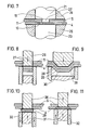
- FIG. 7 shows a second exemplary embodiment in which the leveling process is carried out at a separate work station.
- the steps shown in FIGS. 1 to 3 are carried out at the first work station, while here only the leveling process shown in FIG. 5 is carried out for the separate work station.
- the diameter of the leveling ram 23 is in any case so large that it covers the bleck wart formed by the joining or the drawn plate parts 10 and 11.
- FIG. 8 to 11 show the third exemplary embodiment in which a punching cam is subsequently leveled.
- a stamping and pressing stamp 26 which can be moved back and forth by appropriate devices, cuts through the plates 5 and 4 at the points 27 and leaves lateral sections 28 which are only deep-drawn.
- 8 shows a cross section at which the interfaces can be seen
- FIG. 9 shows a section rotated by 90 ° with respect to FIG. 8, from which the deep-drawn connection can be seen.
- Fig. 10 it is shown how the pressed-out sheet metal parts 29 and 30 are squeezed by moving an anvil 31 upwards by the punching and pressing punch 26 remaining. As a result, at least the sheet metal section becomes at the interfaces 29 expands and engages behind the lower plate 4. In order to allow a flow of material, the die 32 was moved slightly downwards for this squeezing process.
- Fig. 11 shows the leveling process again, in which the punching and pressing die 26 has moved slightly upwards, in order to again create a space for receiving crushed material and in which the anvil 31 and the die 32 now form a common press die up to the plane of the plates 4 and 5 are shifted.
Landscapes
- Engineering & Computer Science (AREA)
- Mechanical Engineering (AREA)
- Shaping Metal By Deep-Drawing, Or The Like (AREA)
- Connection Of Plates (AREA)
- Perforating, Stamping-Out Or Severing By Means Other Than Cutting (AREA)
- Lining Or Joining Of Plastics Or The Like (AREA)
- Forging (AREA)
- Press Drives And Press Lines (AREA)
- Pressure Welding/Diffusion-Bonding (AREA)
- Arc Welding In General (AREA)
- Non-Reversible Transmitting Devices (AREA)
- Coupling Device And Connection With Printed Circuit (AREA)
Abstract
Description
Die Erfindung geht aus von einem Verfahren zum Verbinden aufeinanderliegender dünner Platten (insbesondere Bleche) nach der Gattung des Hauptanspruchs sowie der Gattung des Anspruchs 4 bzw. des Anspruchs 7.The invention is based on a method for connecting superimposed thin plates (in particular sheets) according to the type of the main claim and the type of
Diese gattungsgemäße Verbindungstechnik weist eine vielfältige Anwendung auf, da sie ohne zusätzliche Hilfsfügeteile, wie Nieten, Schrauben und dgl., auskommt, ohne daß deshalb die Verbindungsqualität schlechter wäre. Derartige Verbindungen sind nicht nur erheblichen Zugkräften, sondern auch Scherkräften aussetzbar und weisen neben der Kraftschlüssigkeit stets eine Formschlüssigkeit an der Verbindungsstelle zwischen den Platten auf, wobei trotz aller Vorteile ein Nachteil bestehen bleibt, daß nämlich die durch das Fügeelement gebildete Blechwarze aus der Plattenebene herausragt, so daß diese Art von Verbindungstechnik nicht überall einsetzbar ist. An diesen Blechwarzen können andere Gegenstände hängenbleiben bzw. sie stellen ungewünschte Erhebungen beispielsweise an zu lackierenden Teilen dar.This generic connection technology has a wide range of applications, since it does not require any additional auxiliary parts, such as rivets, screws and the like, without the connection quality being therefore poorer. Such connections are not only subject to considerable tensile forces, but also shear forces and, in addition to the frictional connection, always have a positive connection at the connection point between the plates, although despite all the advantages there remains a disadvantage that the sheet metal projection formed by the joining element protrudes from the plate plane, so that this type of connection technology cannot be used everywhere. Other objects can get caught on these sheet metal warts or they represent undesired elevations, for example on parts to be painted.
Ein bekanntes Verfahren der gattungsgemäßen Art (US-PS 3 934 327) stellt Stanznocken her, in dem nach einem Tiefzieh- und Stanzvorgang sich eine Quetschbearbeitung anschließt, wobei das den Platten nähere Plattenstück durch Quetschen verbreitert wird und mit seinen Rändern die Platten hintergreift (Clinchen). Damit die Blechwarze möglichst wenig aus der Plattenebene herausragt, wird durch zusätzliche Preßwerkzeuge in die Platten eine Mulde eingeprägt, innerhalb welcher dann der Stanznocken gebildet wird, so daß dessen Fügeteile nur unwesentlich über diese Mulde herausragen. Der Nachteil besteht allerdings darin, daß nun auf beiden Seiten der zu verbindenden Platten Erhebungen vorhanden sind, so daß das eingangs genannte Problem nicht behoben, sondern nur verlagert ist.A known method of the generic type (US Pat. No. 3,934,327) produces punching cams in which a crushing operation follows after a deep-drawing and punching process, the plate piece closer to the plates being widened by squeezing and engaging behind the plates with its edges (clinching ). So that the sheet metal projection protrudes as little as possible from the plane of the plate, a depression is embossed into the plates by means of additional pressing tools, within which the punching cam is then formed, so that its joining parts protrude only insignificantly from this depression. The disadvantage, however, is that there are now elevations on both sides of the plates to be connected, so that the problem mentioned at the outset is not resolved, but only relocated.
Bei einem anderen bekannten gattungsgemäßen Verfahren mit entsprechender Vorrichtung (DE-OS 35 32 900) steht für das Fügeelement, soweit es aus der Plattenebene herausragt, nur ein begrenztes Volumen zur Verfügung, welches durch die Größe einer Sacköffnung im Gesenk bestimmt wird. Durch dieses Verfahren wird zwar eine feste Verbindung bei nur geringem Herausragen der Blechwarze erreicht mit wenigstens einer glatten Plattenseite, es verbleibt jedoch der Nachteil dieser Fügeelementnoppen.In another known generic method with a corresponding device (DE-OS 35 32 900), there is only a limited volume available for the joining element, insofar as it protrudes from the plate level, which is determined by the size of a pocket opening in the die. Although this method achieves a firm connection with only a slight protrusion of the sheet metal nipple with at least one smooth plate side, the disadvantage of these joining element knobs remains.
Das erfindungsgemäße Verfahren nach den kennzeichnenden Merkmalen des Hauptanspruchs hat demgegenüber den Vorteil, daß nach dem Verbinden der Platten keine aus der Plattenebene herausragenden Teile, wie Blechwarzen, vorhanden sind, wobei die verbleibenden Sacköffnungen auf der Plattenfläche, auf der der Stempel eingesetzt wurde kleiner als bei den bekannten Verfahren sind, außerdem aber untergeordneter Bedeutung sind. Durch Einsatz der Erfindung kann somit diese Verbindungstechnik in weit größerem Umfang eingesetzt werden, ohne daß deshalb damit eine wesentliche Verteuerung verbunden ist. Ein wesentlicher und vor allem überraschender Vorteil der Erfindung besteht darin, daß durch die zusätzliche Materialverformung im Fügeelement eine erhebliche Steigerung der Festigkeit, besonders auf Scherung, erreicht wird, die bis zu 100 % im Vergleich zu einer unplanierten Verbindung gehen kann. Außerdem wird auch die dynamische Festigkeit verbessert. Der zusätzliche Aufwand beim der Einsatz der Erfindung, beispielsweise durch ein Mehrplatzsystem oder beim Einplatzsystem durch eine Veränderung der Werkzeuge, tritt im Vergleich zu den gewonnenen Vorteilen in den meisten Fällen in den Hintergrund, auch wenn es sich um ein bereits sehr durchrationalisiertes Verfahren handelt, wie es als bekannt oben beschrieben ist.The inventive method according to the characterizing features of the main claim has the advantage that after joining the plates no protruding parts from the plate level, such as sheet metal warts, are present, the remaining blind openings on the plate surface on the the stamp was used smaller than in the known methods, but are also of minor importance. By using the invention, this connection technology can thus be used to a much greater extent without being associated with any significant increase in price. An essential and, above all, surprising advantage of the invention is that the additional material deformation in the joining element leads to a considerable increase in strength, particularly with regard to shear, which can be up to 100% compared to an unplaned connection. Dynamic strength is also improved. The additional effort when using the invention, for example through a multi-user system or with a single-user system by changing the tools, in most cases takes a back seat in comparison to the advantages gained, even if it is an already very rationalized process, such as it is described as known above.
Die erfindungsgemäße Vorrichtung mit den kennzeichnenden Merkmalen des Anspruches 4 greift auf Erfahrungen zurück, wie sie seit langem in dieser Verbindungstechnik vorhanden sind, nämlich auf zweiteilige Werkzeuge mit einer Matritze, deren Boden verschiebbar ist und einerseits als Gesenkboden dient und andererseits beim Planiervorgang als Stempelboden dient. Grundsätzlich gleiches gilt für den eigentlichen Stempel, der zu Beginn des Fügevorgangs seine Stempelfunktion wahrnimmt und dann beim Planiervorgang durch leichtes Zurückfahren als Kalibrierstempel wirkt. Natürlich kann das den eigentlichen Stempel umgebende Führungsteil, beispielsweise eine Buchse bereits zu Beginn des Tiefzieh- oder auch Stanzvorgangs auf die Platten gefahren werden, um diese gemeinsam mit dem Matritzenwerkzeug festzuspannen.The device according to the invention with the characterizing features of
Nach einer weiteren Ausgestaltung der Erfindung ist dieser Stempel in den Führungsteil in Kraftrichtung nachgiebig gelagert, wobei die Nachgiebigkeit erst bei der Planierkraft zur Auswirkung kommt, so daß beim Tiefzieh- und auch Quetschvorgang der Stempel im Führungsteil in seiner Stellung relativ zu diesem verharrt und erst, wenn die starke Planierkraft von der Matritzenseite her auftritt, nachgibt, um ausreichend Platz für das weggequetschte Material zur Verfügung zu stellen.According to a further embodiment of the invention, this stamp is resiliently mounted in the guide part in the direction of force, the flexibility only having an effect on the leveling force, so that during the deep-drawing and also crushing process the stamp remains in its position relative to the guide part and only, when the strong leveling force occurs from the die side, gives way to provide enough space for the squeezed material.
Die Vorrichtung mit den kennzeichnenden Merkmalen des Anspruchs 7 hat gegenüber den bekannten Vorrichtungen den Vorteil, daß ein verhältnismäßig geringer zusätzlicher Werkzeugaufwand erforderlich ist und daß einfache Werkzeuge einsetzbar sind, was sich vor allem auf die Lebensdauer dieser Werkzeuge auswirkt.The device with the characterizing features of claim 7 has the advantage over the known devices that a relatively small additional tool effort is required and that simple tools can be used, which affects above all the life of these tools.
Erfindungsgemäß kann für das Planieren auch eine Walzvorrichtung dienen, insbesondere mit einem Walzenpaar, von denen eine Walze glattflächig ist, hingegen die andere Walze Kalibrierdorne aufweist, die in die bereits durch den vorangegangenen Fügevorgang entstandenen Sacköffnungen greifen.According to the invention, a roller device can also be used for the leveling, in particular with a pair of rollers, one roller of which has a smooth surface, while the other roller has calibration mandrels which engage in the blind openings already created by the previous joining process.
Weitere Vorteile und vorteilhafte Ausgestaltungen der Erfindung sind der nachfolgenden Beschreibung, der Zeichnung und den Ansprüchen entnehmbar.Further advantages and advantageous embodiments of the invention can be found in the following description, the drawing and the claims.
Drei Ausführungsbeispiele des Gegenstandes der Erfindung sind in der Zeichnung dargestellt und werden im folgenden näher beschrieben. Es zeigen
- Fig. 1 bis 5 das erste Ausführungsbeispiel mit einem einen runden Fügepunkt erzeugende Werkzeug im Längsschnitt und in fünf verschiedenen Arbeitsstellungen einer Arbeitsstation,
- Fig. 6 eine Ausgestaltung des Stempels dieses Werkzeugs,
- Fig. 7 das zweite Ausführungsbeispiel im Längsschnitt in Endstellung des Werkzeugs bei einem Mehrarbeitsplatzverfahren und
- Fig. 8 bis 11 das dritte Ausführungsbeispiel in drei verschiedenen Arbeitsstellungen und im Längsschnitt.
- 1 to 5 the first embodiment with a tool generating a round joining point in longitudinal section and in five different working positions of a work station,
- 6 shows an embodiment of the stamp of this tool,
- Fig. 7 shows the second embodiment in longitudinal section in the end position of the tool in a multi-job process and
- 8 to 11 the third embodiment in three different working positions and in longitudinal section.
In den Figuren 1 bis 6 ist das erste Ausführungsbeispiel gezeigt als Werkzeugbeispiel, wobei nur das eigentliche Herstellungswerkzeug in fünf verschiedenen Arbeitsstellungen sowie die zu verbindenden Platten dargestellt sind. Natürlich gehört zur Vollständigkeit der Erfindung auch die Pressvorrichtung, die in unterschiedlichster Weise gestaltet sein kann und durch die für die Durchführung der erfindungsgemäßen Verbindung das Werkzeug betätigt werden muß.In Figures 1 to 6, the first embodiment is shown as a tool example, only the actual manufacturing tool in five different working positions and the plates to be connected are shown. Of course, the completeness of the invention also includes the pressing device, which can be designed in a wide variety of ways and by means of which the tool must be actuated in order to carry out the connection according to the invention.
Das Werkzeug besteht aus einem Stempel 1 einer Matritze 2 und einem Amboß 3, der relativ zur Matritze 2 verschiebbar ist. Zwischen dem Stempel 1 und der Matritze 2 sind die zu verbindenden Platten vorhanden, eine untere Platte 4 und eine obere Platte 5. Bei diesen Platten handelt es sich meist um Bleche, wobei natürlich auch mehr als zwei derartige Bleche miteinander verbunden werden können.The tool consists of a
Um den Stempel 1 ist eine Buchse 6 (Führungsteil) angeordnet, die relativ zum Stempel 1 verschiebbar ist. Aus der Buchse 6 heraus ragt ein entsprechend in der Länge änderbarer Arbeitszapfen 7. Der oberen Platte 5 ist die Schulter 8 der Buchse 6 zugewandt sowie die Stirnfläche 9 des Arbeitszapfens 7.A bushing 6 (guide part) is arranged around the
In Fig. 2 ist der erste Teil des Arbeitsvorgangs, nämlich das Tiefziehen beendet, bei dem der Arbeitszapfen 7 die seiner freien Stirnfläche 9 vorgelagerten Plattenanteile 10 und 11 der beiden Platten 4 und 5 zu einer Sacköffnung tiefgezogen hat. Hierbei entsteht eine topfartige Verbindung zwischen den in der ursprünglichen Lage verbleibenden Platten und den tiefgezogenen Plattenanteilen 10 und 11 mit einer entsprechenden Verdünnung des Materials dieser Anteile, ohne daß deshalb ein Ineinanderhaken der Platten 4 und 5 bewirkt wurde.2, the first part of the working process, namely the deep-drawing, has ended, in which the working pin 7 has deep-drawn the
In Fig. 3 nimmt der Formstempel 1 seine Endlage ein, in der die tiefgezogenen Plattenanteile 10 und 11 bereits gequetscht wurden. In dieser Stellung liegt die Schulter 8 an der Oberfläche der Platte 5 an. Die der Stirnfläche 9 gegenüberliegenden Plattenanteile sind durch den Widerstand des Amboß 3 und der begrenzenden Matritze 2 stark zusammengepreßt, wobei das Material radial nach außen verdrängt wurde. Aufgrund der Quetschwirkung wurden die tiefgezogenen Plattenanteile so weit zu einem hier horizontal dargestellten Quetschteil radial ausgedehnt, daß dieser hinter die Tiefziehöffnung 14 der unteren Platte 4 greift. Bereits nach diesem Arbeitsschritt ist eine formschlüssige äußerst feste Verbindung durch ein Ineinanderfließen des Plattenmaterials erzielt.In Fig. 3, the die 1 assumes its end position in which the deep-drawn
In Fig. 4 ist der Formstempel 1 innerhalb der Buchse 6 leicht nach oben gezogen, so daß ein Hohlraum 15 entsteht.In Fig. 4, the
In Fig. 5 nimmt das Werkzeug die Endstellung nach einem Planiervorgang der beiden Plattenanteile 10 und 11 also der gesamten Bearbeitung ein, bei der der Amboß 3 bis in die Ebene der Platten 4 und 5 nach oben geschoben wurde und dadurch die tiefgezogenen Anteile 10, 11 in die Plattenebene verdrängt hat. Das dabei verdrängte Material füllt den vorher gebildeten Hohlraum 15 aus, wobei der Formstempel 1 als Kalibrierstempel fungiert und die Buchse 6 als Widerstandslager.5, the tool assumes the end position after a leveling operation of the two
Natürlich ist auch denkbar, daß bei diesem, in den Figuren 4 und 5 dargestellten, Planiervorgang zuerst die Matritze 2 mit ihrer Stirnfläche bis auf die Stirnflächenebene des Amboß 3 zurückgefahren wird, um danach einen gemeinsamen flachen Preßstempel bildend für das Planieren wieder in Richtung Formstempel 1 bzw. Buchse 6 zum Planieren verschoben zu werden.Of course, it is also conceivable that in this leveling process, shown in FIGS. 4 and 5, first the
In Fig. 6 ist eine Ausgestaltung von Buchse 6 und Planierstempel 7 dargestellt, in dem sich der Planierstempel 7 über einen Bund 16 an einem elastischen Material 17, beispielsweise einer Feder, abstützt und wobei sein Hub durch einen Anschlag 18 begrenzt ist. Dieses elastische Material 17 ist so ausgebildet, daß es beim Tiefzieh- und Quetschvorgang nicht nachgibt, sondern erst beim Planiervorgang, des heißt beim Verschieben des Amboß 3 in Richtung Platten 4, 5. Hierdurch wird ein extra, den Formstempel 7 innerhalb der Buchse 6 betätigendes Werkzeug eingespart.6 shows an embodiment of the
In Fig. 7 ist ein zweites Ausführungsbeispiel dargestellt, bei dem der Planiervorgang an einem separaten Arbeitsplatz durchgeführt wird. Am ersten Arbeitsplatz werden die, in den Fig. 1 bis 3 gezeigten Schritte durchgeführt, während hier am separaten Arbeitsplatz nur der in Fig. 5 gezeigte Planiervorgang für sich durchgeführt wird. Hierfür ist ein spezieller Kalibrierstempel 21 vorhanden, mit einem Kalibrierzapfen 22 und es ist ein extra Planierstempel 23 vorgesehen, wobei durch Haltevorrichtungen 24 und 25 die Platten 4 und 5 eingespannt werden. Da die Platten bereits durch das Fügeelement miteinander verbunden waren, dienen diese Haltevorrichtungen 24 und 25 vor allem dazu, ein exaktes Einfahren des Kalibrierstempels 21 in die vorhandene Sacköffnung 15 zu bewirken. Der Durchmesser des Planierstempels 23 ist in jedem Fall so groß, daß er die durch das Fügen gebildete Bleckwarze bzw. die gezogenen Plattenanteile 10 und 11 überdeckt.FIG. 7 shows a second exemplary embodiment in which the leveling process is carried out at a separate work station. The steps shown in FIGS. 1 to 3 are carried out at the first work station, while here only the leveling process shown in FIG. 5 is carried out for the separate work station. For this purpose there is a
In den Fig. 8 bis 11 ist das dritte Ausführungsbeispiel dargestellt, bei dem ein Stanznocken nachträglich planiert wird. Ein Stanz- und Drückstempel 26, der durch entsprechende Vorrichtungen hin und her bewegbar ist, durchschneidet die Platten 5 und 4 an den Stellen 27 und läßt seitliche Abschnitte 28 stehen, die lediglich tiefgezogen werden. Während Fig. 8 einen Querschnitt zeigt, an dem die Schnittstellen zu sehen sind, zeigt Fig. 9 einen gegenüber Fig. 8 um 90° verdrehten Schnitt, aus dem die Tiefziehverbindung erkennbar ist.8 to 11 show the third exemplary embodiment in which a punching cam is subsequently leveled. A stamping and pressing
In Fig. 10 ist gezeigt, wie die herausgedrückten Blechteile 29 und 30 durch das Nachobenfahren eines Amboß 31 gequetscht werden, indem der Stanz- und Drückstempel 26 stehen bleibt. An den Schnittstellen wird dadurch mindestens der Blechabschnitt 29 erweitert und hintergreift damit die untere Platte 4. Um einen Materialfluß zu ermöglichen, wurde für diesen Quetschvorgang die Matritze 32 leicht nach unten gefahren.In Fig. 10 it is shown how the pressed-out
Fig. 11 zeigt dann wieder den Planierablauf, bei dem der Stanz- und Drückstempel 26 leicht nach oben gefahren ist, um wiederum einen Raum zur Aufnahme gequetschten Materiales zu schaffen und bei dem der Amboß 31 und die Matritze 32 nunmehr einen gemeinsamen Preßstempel bildend bis in die Ebene der Platten 4 und 5 verschoben werden.Fig. 11 then shows the leveling process again, in which the punching and pressing die 26 has moved slightly upwards, in order to again create a space for receiving crushed material and in which the
Alle in der Beschreibung, den nachfolgenden Ansprüchen und der Zeichnung dargestellten Merkmale können sowohl einzeln, als auch in beliebiger Kombination miteinander erfindungswesentlich sein.All of the features shown in the description, the following claims and the drawing can be essential to the invention both individually and in any combination with one another.
Claims (9)
gekennzeichnet durch
marked by
Priority Applications (1)
| Application Number | Priority Date | Filing Date | Title |
|---|---|---|---|
| AT88104218T ATE91654T1 (en) | 1987-04-01 | 1988-03-17 | METHOD AND DEVICE FOR JOINING SUPPLIED THIN PANELS. |
Applications Claiming Priority (2)
| Application Number | Priority Date | Filing Date | Title |
|---|---|---|---|
| DE19873710929 DE3710929A1 (en) | 1987-04-01 | 1987-04-01 | METHOD AND DEVICE FOR CONNECTING LAYER THIN PLATES |
| DE3710929 | 1987-04-01 |
Publications (3)
| Publication Number | Publication Date |
|---|---|
| EP0284902A2 true EP0284902A2 (en) | 1988-10-05 |
| EP0284902A3 EP0284902A3 (en) | 1990-06-06 |
| EP0284902B1 EP0284902B1 (en) | 1993-07-21 |
Family
ID=6324608
Family Applications (1)
| Application Number | Title | Priority Date | Filing Date |
|---|---|---|---|
| EP88104218A Revoked EP0284902B1 (en) | 1987-04-01 | 1988-03-17 | Method and apparatus to join thin plates lying one on top of the other together |
Country Status (9)
| Country | Link |
|---|---|
| US (1) | US4831711A (en) |
| EP (1) | EP0284902B1 (en) |
| JP (1) | JPS63256231A (en) |
| KR (1) | KR930012252B1 (en) |
| AT (1) | ATE91654T1 (en) |
| AU (1) | AU598355B2 (en) |
| BR (1) | BR8801516A (en) |
| DE (2) | DE3710929A1 (en) |
| ES (1) | ES2041718T3 (en) |
Cited By (7)
| Publication number | Priority date | Publication date | Assignee | Title |
|---|---|---|---|---|
| DE4139347A1 (en) * | 1991-11-29 | 1993-06-03 | Sta Co Mettallerzeugnisse Gmbh | PRESSURE JOINT DEVICE |
| EP0546270A1 (en) * | 1991-11-13 | 1993-06-16 | ECKOLD GmbH & Co. KG | Method of transforming brittle material |
| EP0601281A1 (en) * | 1992-12-05 | 1994-06-15 | ECKOLD GmbH & Co. KG | A method for joining superposed metal sheets and a tool set for producing such joints |
| DE4432639A1 (en) * | 1994-09-14 | 1996-03-28 | Meinig Metu System | Method of joining together two or more layers of sheets |
| DE10245604A1 (en) * | 2002-09-30 | 2004-04-15 | Fraunhofer-Gesellschaft zur Förderung der angewandten Forschung e.V. | Method and device for the permanent connection of overlapping, plate-shaped components |
| DE10250342A1 (en) * | 2002-10-29 | 2004-05-19 | Daimlerchrysler Ag | Jointing process for connecting overlapping components involves exerting counter-pressure to deform first component to form undercut in stamped region of second one |
| EP2921241A1 (en) * | 2014-03-18 | 2015-09-23 | BTM Corporation | Clinching apparatus and method for making such a clinching apparatus |
Families Citing this family (43)
| Publication number | Priority date | Publication date | Assignee | Title |
|---|---|---|---|---|
| SE8800407D0 (en) * | 1988-02-05 | 1988-02-05 | Cerac Sa | A METHOD FOR JOINING TWO OR SEVERAL OVERLAYING SHEET FORMED MEMBERS TOGETHER, METAL OR NON-METAL, AND AN APPARATUS FOR CARRYING OUT SAID METHOD |
| DE3934743A1 (en) * | 1989-10-18 | 1991-04-25 | Eckold Vorrichtung | METHOD FOR CONNECTING TWO COMPONENTS |
| DE4012206C2 (en) * | 1990-04-14 | 1994-02-17 | Porsche Ag | Composite element |
| US5432989A (en) * | 1992-10-27 | 1995-07-18 | Archer Manufacturing Corporation | Apparatus and method for joining sheet material |
| JP2583201B2 (en) * | 1994-08-05 | 1997-02-19 | 株式会社エナミ精機 | Joint structure between metal plates |
| GB9616849D0 (en) * | 1996-08-10 | 1996-09-25 | T & N Technology Ltd | Forming a composite panel |
| US5939212A (en) * | 1997-06-09 | 1999-08-17 | Atd Corporation | Flexible corrugated multilayer metal foil shields and method of making |
| US6047511A (en) * | 1998-03-04 | 2000-04-11 | Usg Interiors, Inc. | Grid tee with integrally stitched web |
| TW556074B (en) * | 1998-12-15 | 2003-10-01 | Foxconn Prec Components Co Ltd | Heat sink and the manufacturing method thereof |
| US6231944B1 (en) | 1999-07-27 | 2001-05-15 | Lydall, Inc. | Method for producing a thermal, acoustical and/or vibrational abatement shield and shield produced thereby |
| US6205641B1 (en) * | 1999-09-29 | 2001-03-27 | Lucent Technologies, Inc. | Anvil assembly for a press for assembling a fastener into a workpiece |
| US6345438B1 (en) * | 2000-06-08 | 2002-02-12 | Homac Manufacturing Company | Method for making bus and post electrical connector using locking pins |
| US7534501B2 (en) | 2000-08-17 | 2009-05-19 | Industrial Origami, Inc. | Precision-folded, high strength, fatigue-resistant structures and sheet therefor |
| US6493907B2 (en) | 2001-01-12 | 2002-12-17 | Honeywell International Inc. | Wire terminal fastener and method |
| DE10292020D2 (en) * | 2001-05-11 | 2004-05-27 | Tox Pressotechnik Gmbh | Tool for mechanically connecting panels |
| DE10130723C2 (en) * | 2001-06-21 | 2003-10-09 | Zebras Zentrum Fuer Entwicklun | Method and device for producing a cold pressure welding connection between overlapping plate-shaped components |
| DE10130726C2 (en) * | 2001-06-21 | 2003-07-03 | Zebras Zentrum Fuer Entwicklun | Method and device for producing a connection between overlapping plate-shaped components |
| WO2005078344A1 (en) * | 2004-02-05 | 2005-08-25 | Beckett Gas, Inc. | Burner |
| JP4148152B2 (en) * | 2004-02-16 | 2008-09-10 | マツダ株式会社 | Friction spot joint structure |
| RU2308344C2 (en) * | 2005-10-26 | 2007-10-20 | Мемжанов Николай Османович | Part block joining method and force spot for joining parts of block |
| EP1969687A4 (en) * | 2005-12-22 | 2011-05-18 | Ind Origami Inc | METHOD FOR JOINING PLANAR SHEETS AND CORRESPONDING SHEETS |
| US7479600B2 (en) * | 2006-06-15 | 2009-01-20 | Group Dekko, Inc. | Electrical bus and method for forming an electrical bus |
| KR20090074267A (en) | 2006-10-26 | 2009-07-06 | 인더스트리얼 오리가미, 인크. | How to form a three-dimensional object |
| US8202628B2 (en) * | 2006-12-08 | 2012-06-19 | Musashi Seimitsu Kogyo Kabushiki Kaisha | Fusion-bonded product having high-strength part and manufacturing method thereof |
| EP2118553A4 (en) | 2007-02-09 | 2014-04-16 | Ind Origami Inc | THREE DIMENSIONAL STRUCTURE CARRYING A LOAD |
| DE502008000600D1 (en) * | 2007-02-13 | 2010-06-10 | Inventio Ag | METHOD AND TOOL FOR CLAMPING THICK SHEETS, AND USE OF THE TOOL |
| JP2009026842A (en) * | 2007-07-18 | 2009-02-05 | Isesaki Homing:Kk | Method of connecting and fixing metal plate, board supporting stand, rail having the board supporting stand, and board setting jig |
| US8757558B2 (en) * | 2007-12-17 | 2014-06-24 | Mp Husky, Llc | Cable tray |
| WO2009110298A1 (en) * | 2008-02-17 | 2009-09-11 | Mori Shohei | Paper binding method and paper binding member, and paper binding device and paper product related thereto |
| US7762034B2 (en) * | 2008-09-26 | 2010-07-27 | Chicago Metallic Corporation | Rotary stitch for joining sheet metal stock |
| US8024848B2 (en) * | 2008-10-08 | 2011-09-27 | GM Global Technology Operations LLC | Double-action clinching method |
| JP5287432B2 (en) * | 2009-03-31 | 2013-09-11 | トヨタ車体株式会社 | Multi-stage press apparatus and molding method of molded object using the same |
| DE202009007835U1 (en) | 2009-06-03 | 2009-11-26 | Technische Universität Chemnitz | Hybrid composite material consisting of several joining partners |
| DE102009023717B4 (en) * | 2009-06-03 | 2014-05-22 | Technische Universität Chemnitz | Method and device for the production of a hybrid material composite from several compound partners and hybrid material composite produced therewith |
| EP2329905B1 (en) * | 2009-12-03 | 2012-05-30 | Helmholtz-Zentrum Geesthacht Zentrum für Material- und Küstenforschung GmbH | Method for joining metal and plastic workpieces |
| KR101180942B1 (en) * | 2009-12-04 | 2012-09-07 | 현대자동차주식회사 | Suspension arm |
| DE202011000731U1 (en) | 2011-03-30 | 2011-06-01 | Schmitz Cargobull AG, 48341 | Profile carrier for a vehicle chassis and utility vehicle chassis with such a profile carrier |
| US8528187B2 (en) * | 2011-06-17 | 2013-09-10 | Gm Global Technology Operation Llc | Method and apparatus for joining multiple components |
| US8936164B2 (en) * | 2012-07-06 | 2015-01-20 | Industrial Origami, Inc. | Solar panel rack |
| DE102013008323A1 (en) * | 2013-05-08 | 2014-11-13 | Westfalia-Automotive Gmbh | Carrier arrangement for a trailer hitch or a load carrier with plug-in pin |
| JP6161198B2 (en) * | 2013-08-29 | 2017-07-12 | 株式会社Subaru | Dissimilar material joining method |
| DE102013020676B4 (en) | 2013-12-06 | 2023-03-02 | Daimler Truck AG | Suspension unit for a truck cab suspension |
| USD1009309S1 (en) | 2020-04-21 | 2023-12-26 | Rockwool A/S | Grid tee for suspended ceiling |
Citations (2)
| Publication number | Priority date | Publication date | Assignee | Title |
|---|---|---|---|---|
| US3934327A (en) | 1974-08-16 | 1976-01-27 | Hafner Otto P | Method of interlocking overlapping sheet material |
| DE3532900A1 (en) | 1985-09-14 | 1987-03-26 | Eugen Rapp | Method and apparatus for connecting thin plates |
Family Cites Families (16)
| Publication number | Priority date | Publication date | Assignee | Title |
|---|---|---|---|---|
| US2122557A (en) * | 1936-08-14 | 1938-07-05 | Canter Morris | Method and apparatus for applying metallic seals |
| US2254558A (en) * | 1938-10-10 | 1941-09-02 | Ivan A Williams | Fastening element and method of making same |
| NL133141C (en) * | 1964-05-20 | |||
| DE1652624A1 (en) * | 1968-03-14 | 1971-09-16 | Fraze Ermal C | Method for manufacturing a rivet and tooling device for carrying out the method |
| US3771216A (en) * | 1971-10-27 | 1973-11-13 | Johnson Die & Eng Co | Method and tooling for extruding a closed end rivet |
| JPS5659540A (en) * | 1979-10-19 | 1981-05-23 | Toshiba Corp | Joining device of plate material |
| JPS56114536A (en) * | 1980-02-13 | 1981-09-09 | Toshiba Corp | Joining device of sheet material |
| US4757609A (en) * | 1980-09-08 | 1988-07-19 | Btm Corporation | Apparatus for joining sheet material |
| JPS57195541A (en) * | 1981-05-29 | 1982-12-01 | Toshiba Corp | Joining method for plates |
| JPS58188522A (en) * | 1982-04-30 | 1983-11-04 | Mitsubishi Electric Corp | Sealing of superposed metallic plates |
| US4531279A (en) * | 1982-08-23 | 1985-07-30 | Robertshaw Controls Company | Method of making a leakproof joint |
| US4601090A (en) * | 1982-08-23 | 1986-07-22 | Robertshaw Controls Company | Leakproof joint construction and apparatus for making the same |
| JPS61249635A (en) * | 1985-04-26 | 1986-11-06 | Enami Seiki:Kk | Joining method for platelike member |
| DE3532899A1 (en) * | 1985-09-14 | 1987-03-26 | Eugen Rapp | METHOD AND DEVICE FOR CONNECTING PANELS BY PUNCHING CAMS |
| DE3679364D1 (en) * | 1985-09-14 | 1991-06-27 | Eugen Rapp | METHOD AND DEVICE FOR CONNECTING THIN PLATES. |
| JP3159061B2 (en) * | 1996-06-21 | 2001-04-23 | 松下電工株式会社 | Method of manufacturing metal foil-laminated laminate |
-
1987
- 1987-04-01 DE DE19873710929 patent/DE3710929A1/en active Granted
-
1988
- 1988-03-17 DE DE8888104218T patent/DE3882407D1/en not_active Expired - Lifetime
- 1988-03-17 EP EP88104218A patent/EP0284902B1/en not_active Revoked
- 1988-03-17 AT AT88104218T patent/ATE91654T1/en not_active IP Right Cessation
- 1988-03-17 ES ES198888104218T patent/ES2041718T3/en not_active Expired - Lifetime
- 1988-03-30 BR BR8801516A patent/BR8801516A/en not_active Application Discontinuation
- 1988-03-31 AU AU14084/88A patent/AU598355B2/en not_active Ceased
- 1988-04-01 JP JP63082111A patent/JPS63256231A/en active Granted
- 1988-04-01 KR KR1019880003689A patent/KR930012252B1/en not_active Expired - Fee Related
- 1988-04-01 US US07/176,552 patent/US4831711A/en not_active Expired - Fee Related
Patent Citations (2)
| Publication number | Priority date | Publication date | Assignee | Title |
|---|---|---|---|---|
| US3934327A (en) | 1974-08-16 | 1976-01-27 | Hafner Otto P | Method of interlocking overlapping sheet material |
| DE3532900A1 (en) | 1985-09-14 | 1987-03-26 | Eugen Rapp | Method and apparatus for connecting thin plates |
Cited By (10)
| Publication number | Priority date | Publication date | Assignee | Title |
|---|---|---|---|---|
| EP0546270A1 (en) * | 1991-11-13 | 1993-06-16 | ECKOLD GmbH & Co. KG | Method of transforming brittle material |
| DE4139347A1 (en) * | 1991-11-29 | 1993-06-03 | Sta Co Mettallerzeugnisse Gmbh | PRESSURE JOINT DEVICE |
| EP0545240A1 (en) * | 1991-11-29 | 1993-06-09 | DE-STA-CO METALLERZEUGNISSE GmbH | Clamping device for clinch joining |
| EP0601281A1 (en) * | 1992-12-05 | 1994-06-15 | ECKOLD GmbH & Co. KG | A method for joining superposed metal sheets and a tool set for producing such joints |
| LT3140B (en) | 1992-12-05 | 1995-01-31 | Eckold Vorrichtung | A method for joining superposed metal sheets and a tool set for producing such joints |
| US5517743A (en) * | 1992-12-05 | 1996-05-21 | Eckold Gmbh & Co. Kg | Method and apparatus for joining superposes metal sheets |
| DE4432639A1 (en) * | 1994-09-14 | 1996-03-28 | Meinig Metu System | Method of joining together two or more layers of sheets |
| DE10245604A1 (en) * | 2002-09-30 | 2004-04-15 | Fraunhofer-Gesellschaft zur Förderung der angewandten Forschung e.V. | Method and device for the permanent connection of overlapping, plate-shaped components |
| DE10250342A1 (en) * | 2002-10-29 | 2004-05-19 | Daimlerchrysler Ag | Jointing process for connecting overlapping components involves exerting counter-pressure to deform first component to form undercut in stamped region of second one |
| EP2921241A1 (en) * | 2014-03-18 | 2015-09-23 | BTM Corporation | Clinching apparatus and method for making such a clinching apparatus |
Also Published As
| Publication number | Publication date |
|---|---|
| BR8801516A (en) | 1988-11-08 |
| DE3882407D1 (en) | 1993-08-26 |
| AU598355B2 (en) | 1990-06-21 |
| ES2041718T3 (en) | 1993-12-01 |
| DE3710929A1 (en) | 1988-10-13 |
| AU1408488A (en) | 1988-10-06 |
| JPH0469493B2 (en) | 1992-11-06 |
| JPS63256231A (en) | 1988-10-24 |
| DE3710929C2 (en) | 1989-02-02 |
| EP0284902B1 (en) | 1993-07-21 |
| US4831711A (en) | 1989-05-23 |
| KR880012357A (en) | 1988-11-26 |
| ATE91654T1 (en) | 1993-08-15 |
| KR930012252B1 (en) | 1993-12-28 |
| EP0284902A3 (en) | 1990-06-06 |
Similar Documents
| Publication | Publication Date | Title |
|---|---|---|
| EP0284902B1 (en) | Method and apparatus to join thin plates lying one on top of the other together | |
| DE69317303T3 (en) | SELF-PUNCHED RIVETS | |
| DE4333052C2 (en) | Self-punching fastening device | |
| DE10041281C2 (en) | Device for forming blanks from flexibly rolled metal strip | |
| EP0215385B1 (en) | Method and device for joining plates by means of punch-fasteners | |
| DE4404659B4 (en) | Method for producing a riveted connection and tool for carrying out the method | |
| WO2005122337A1 (en) | Press-in contact and method for the production thereof | |
| DE2406361A1 (en) | Flanged bushes formed from single blank - is formed in two operations to avoid stressing blank shaped to developed profile | |
| DE2128767C3 (en) | Overall composite tool | |
| EP1549447B1 (en) | Method and device for permanently joining overlapping, plate-shaped parts | |
| DE102013217213A1 (en) | METHOD FOR IMPLEMENTING AND FIXING AN ATTACHMENT ELEMENT AND CORRESPONDING MATRIZE | |
| DE3208867A1 (en) | METHOD AND DEVICE FOR BENDING LONG-STRETCHED PARTS | |
| DE102014104146B4 (en) | punch | |
| DE10314544A1 (en) | Forming interlocking connection between thin-walled materials, inserts surface projection through passage in second surface and rivets projection over opening | |
| DE3101995A1 (en) | METHOD FOR PRODUCING ELECTRICAL CONTACTS | |
| DE69708777T2 (en) | Process for cutting a blank from a sheet metal plate | |
| DE4444857C1 (en) | Method for forming opening in wall of esp. exhaust pipe | |
| DE102015008171A1 (en) | Apparatus and method for processing a sheet metal component | |
| DE3016168C2 (en) | Complete composite cutting and bending tool | |
| DE19957076A1 (en) | Method and device for punching sheet metal parts made of an aluminum material | |
| DE2713893A1 (en) | Hand tool for joining sheets of material - has material from one sheet forced into hole in second sheet by pin in jaw of pliers | |
| DE1452574A1 (en) | Method and device for the production of blades with flow profiles | |
| AT167653B (en) | Method and device for the production of flexible and resilient multi-armed tooth brackets for fastening dental prostheses to abutment teeth | |
| DE2909214C2 (en) | Method for producing a pole piece for electrical machines | |
| DE2344831A1 (en) | PROCESS FOR MANUFACTURING CURBLE FITTINGS AND EQUIPMENT FOR CARRYING OUT THE PROCESS |
Legal Events
| Date | Code | Title | Description |
|---|---|---|---|
| PUAI | Public reference made under article 153(3) epc to a published international application that has entered the european phase |
Free format text: ORIGINAL CODE: 0009012 |
|
| AK | Designated contracting states |
Kind code of ref document: A2 Designated state(s): AT BE CH DE ES FR GB GR IT LI LU NL SE |
|
| PUAL | Search report despatched |
Free format text: ORIGINAL CODE: 0009013 |
|
| AK | Designated contracting states |
Kind code of ref document: A3 Designated state(s): AT BE CH DE ES FR GB GR IT LI LU NL SE |
|
| 17P | Request for examination filed |
Effective date: 19900515 |
|
| 17Q | First examination report despatched |
Effective date: 19910325 |
|
| GRAA | (expected) grant |
Free format text: ORIGINAL CODE: 0009210 |
|
| AK | Designated contracting states |
Kind code of ref document: B1 Designated state(s): AT BE CH DE ES FR GB GR IT LI LU NL SE |
|
| REF | Corresponds to: |
Ref document number: 91654 Country of ref document: AT Date of ref document: 19930815 Kind code of ref document: T |
|
| ET | Fr: translation filed | ||
| REF | Corresponds to: |
Ref document number: 3882407 Country of ref document: DE Date of ref document: 19930826 |
|
| ITF | It: translation for a ep patent filed | ||
| GBT | Gb: translation of ep patent filed (gb section 77(6)(a)/1977) |
Effective date: 19930812 |
|
| PG25 | Lapsed in a contracting state [announced via postgrant information from national office to epo] |
Ref country code: GR Free format text: LAPSE BECAUSE OF FAILURE TO SUBMIT A TRANSLATION OF THE DESCRIPTION OR TO PAY THE FEE WITHIN THE PRESCRIBED TIME-LIMIT Effective date: 19931022 |
|
| PLBI | Opposition filed |
Free format text: ORIGINAL CODE: 0009260 |
|
| PLAB | Opposition data, opponent's data or that of the opponent's representative modified |
Free format text: ORIGINAL CODE: 0009299OPPO |
|
| REG | Reference to a national code |
Ref country code: ES Ref legal event code: FG2A Ref document number: 2041718 Country of ref document: ES Kind code of ref document: T3 |
|
| 26 | Opposition filed |
Opponent name: ECKOLD GMBH & CO. KG, Effective date: 19931028 |
|
| R26 | Opposition filed (corrected) |
Opponent name: ECKOLD GMBH & CO. KG, Effective date: 19931028 |
|
| NLR1 | Nl: opposition has been filed with the epo |
Opponent name: ECKOLD GMBH & CO. KG, |
|
| PG25 | Lapsed in a contracting state [announced via postgrant information from national office to epo] |
Ref country code: AT Effective date: 19940301 |
|
| PG25 | Lapsed in a contracting state [announced via postgrant information from national office to epo] |
Ref country code: GB Effective date: 19940317 |
|
| PG25 | Lapsed in a contracting state [announced via postgrant information from national office to epo] |
Ref country code: SE Free format text: LAPSE BECAUSE OF NON-PAYMENT OF DUE FEES Effective date: 19940318 Ref country code: ES Free format text: LAPSE BECAUSE OF NON-PAYMENT OF DUE FEES Effective date: 19940318 |
|
| PG25 | Lapsed in a contracting state [announced via postgrant information from national office to epo] |
Ref country code: LU Free format text: LAPSE BECAUSE OF NON-PAYMENT OF DUE FEES Effective date: 19940331 Ref country code: LI Free format text: LAPSE BECAUSE OF NON-PAYMENT OF DUE FEES Effective date: 19940331 Ref country code: CH Free format text: LAPSE BECAUSE OF NON-PAYMENT OF DUE FEES Effective date: 19940331 Ref country code: BE Effective date: 19940331 |
|
| BERE | Be: lapsed |
Owner name: RAPP EUGEN Effective date: 19940331 |
|
| PG25 | Lapsed in a contracting state [announced via postgrant information from national office to epo] |
Ref country code: NL Effective date: 19941001 |
|
| GBPC | Gb: european patent ceased through non-payment of renewal fee |
Effective date: 19940317 |
|
| NLV4 | Nl: lapsed or anulled due to non-payment of the annual fee | ||
| PG25 | Lapsed in a contracting state [announced via postgrant information from national office to epo] |
Ref country code: DE Effective date: 19941117 |
|
| PG25 | Lapsed in a contracting state [announced via postgrant information from national office to epo] |
Ref country code: FR Effective date: 19941130 |
|
| REG | Reference to a national code |
Ref country code: CH Ref legal event code: PL |
|
| REG | Reference to a national code |
Ref country code: FR Ref legal event code: ST |
|
| EUG | Se: european patent has lapsed |
Ref document number: 88104218.8 Effective date: 19941010 |
|
| RDAG | Patent revoked |
Free format text: ORIGINAL CODE: 0009271 |
|
| STAA | Information on the status of an ep patent application or granted ep patent |
Free format text: STATUS: PATENT REVOKED |
|
| 27W | Patent revoked |
Effective date: 19941216 |
|
| PLAB | Opposition data, opponent's data or that of the opponent's representative modified |
Free format text: ORIGINAL CODE: 0009299OPPO |