EP0284282A2 - Thermal ink jet printer - Google Patents
Thermal ink jet printer Download PDFInfo
- Publication number
- EP0284282A2 EP0284282A2 EP88302282A EP88302282A EP0284282A2 EP 0284282 A2 EP0284282 A2 EP 0284282A2 EP 88302282 A EP88302282 A EP 88302282A EP 88302282 A EP88302282 A EP 88302282A EP 0284282 A2 EP0284282 A2 EP 0284282A2
- Authority
- EP
- European Patent Office
- Prior art keywords
- dyestuff
- valve
- printing device
- nozzle
- vapour
- Prior art date
- Legal status (The legal status is an assumption and is not a legal conclusion. Google has not performed a legal analysis and makes no representation as to the accuracy of the status listed.)
- Withdrawn
Links
- 239000000975 dye Substances 0.000 claims abstract description 124
- 230000000694 effects Effects 0.000 claims abstract description 7
- 238000010438 heat treatment Methods 0.000 claims description 23
- 239000003086 colorant Substances 0.000 claims description 10
- WPYMKLBDIGXBTP-UHFFFAOYSA-N benzoic acid group Chemical group C(C1=CC=CC=C1)(=O)O WPYMKLBDIGXBTP-UHFFFAOYSA-N 0.000 claims description 4
- LFQSCWFLJHTTHZ-UHFFFAOYSA-N Ethanol Natural products CCO LFQSCWFLJHTTHZ-UHFFFAOYSA-N 0.000 claims description 3
- 238000005323 electroforming Methods 0.000 claims description 3
- 239000005711 Benzoic acid Substances 0.000 claims description 2
- 235000010233 benzoic acid Nutrition 0.000 claims description 2
- 235000019441 ethanol Nutrition 0.000 claims description 2
- 125000005909 ethyl alcohol group Chemical group 0.000 claims 1
- 239000010410 layer Substances 0.000 description 45
- 239000000758 substrate Substances 0.000 description 40
- 239000012212 insulator Substances 0.000 description 33
- PXHVJJICTQNCMI-UHFFFAOYSA-N Nickel Chemical compound [Ni] PXHVJJICTQNCMI-UHFFFAOYSA-N 0.000 description 24
- 238000000034 method Methods 0.000 description 14
- 125000006850 spacer group Chemical group 0.000 description 13
- 229910052759 nickel Inorganic materials 0.000 description 12
- 208000000884 Airway Obstruction Diseases 0.000 description 11
- 206010008589 Choking Diseases 0.000 description 11
- 239000010408 film Substances 0.000 description 11
- 239000002184 metal Substances 0.000 description 11
- 229910052751 metal Inorganic materials 0.000 description 11
- 230000008569 process Effects 0.000 description 9
- 230000014509 gene expression Effects 0.000 description 8
- 239000000976 ink Substances 0.000 description 8
- 238000010276 construction Methods 0.000 description 7
- 238000007747 plating Methods 0.000 description 5
- 239000011241 protective layer Substances 0.000 description 5
- 239000004642 Polyimide Substances 0.000 description 4
- 229920001721 polyimide Polymers 0.000 description 4
- 239000010409 thin film Substances 0.000 description 4
- 238000007599 discharging Methods 0.000 description 3
- 238000004519 manufacturing process Methods 0.000 description 3
- DITXJPASYXFQAS-UHFFFAOYSA-N nickel;sulfamic acid Chemical compound [Ni].NS(O)(=O)=O DITXJPASYXFQAS-UHFFFAOYSA-N 0.000 description 3
- 230000004044 response Effects 0.000 description 3
- 229910001220 stainless steel Inorganic materials 0.000 description 3
- 239000010935 stainless steel Substances 0.000 description 3
- VYPSYNLAJGMNEJ-UHFFFAOYSA-N Silicium dioxide Chemical compound O=[Si]=O VYPSYNLAJGMNEJ-UHFFFAOYSA-N 0.000 description 2
- 239000003513 alkali Substances 0.000 description 2
- 229910010293 ceramic material Inorganic materials 0.000 description 2
- 230000007797 corrosion Effects 0.000 description 2
- 238000005260 corrosion Methods 0.000 description 2
- 230000005684 electric field Effects 0.000 description 2
- 230000005611 electricity Effects 0.000 description 2
- 238000005530 etching Methods 0.000 description 2
- 239000000463 material Substances 0.000 description 2
- 239000011159 matrix material Substances 0.000 description 2
- 239000007769 metal material Substances 0.000 description 2
- 230000009467 reduction Effects 0.000 description 2
- 239000000126 substance Substances 0.000 description 2
- RYGMFSIKBFXOCR-UHFFFAOYSA-N Copper Chemical compound [Cu] RYGMFSIKBFXOCR-UHFFFAOYSA-N 0.000 description 1
- 102220632628 Immunoglobulin heavy variable 1-69_E22A_mutation Human genes 0.000 description 1
- 239000004952 Polyamide Substances 0.000 description 1
- 229910052581 Si3N4 Inorganic materials 0.000 description 1
- PNEYBMLMFCGWSK-UHFFFAOYSA-N aluminium oxide Inorganic materials [O-2].[O-2].[O-2].[Al+3].[Al+3] PNEYBMLMFCGWSK-UHFFFAOYSA-N 0.000 description 1
- 239000000919 ceramic Substances 0.000 description 1
- 239000003795 chemical substances by application Substances 0.000 description 1
- 229910052681 coesite Inorganic materials 0.000 description 1
- 229910052802 copper Inorganic materials 0.000 description 1
- 239000010949 copper Substances 0.000 description 1
- 229910052593 corundum Inorganic materials 0.000 description 1
- 229910052906 cristobalite Inorganic materials 0.000 description 1
- 230000006866 deterioration Effects 0.000 description 1
- 238000004090 dissolution Methods 0.000 description 1
- 238000001035 drying Methods 0.000 description 1
- 239000011521 glass Substances 0.000 description 1
- 230000020169 heat generation Effects 0.000 description 1
- 230000006872 improvement Effects 0.000 description 1
- 238000009413 insulation Methods 0.000 description 1
- 230000010354 integration Effects 0.000 description 1
- WABPQHHGFIMREM-UHFFFAOYSA-N lead(0) Chemical compound [Pb] WABPQHHGFIMREM-UHFFFAOYSA-N 0.000 description 1
- 239000007788 liquid Substances 0.000 description 1
- 238000012423 maintenance Methods 0.000 description 1
- 230000000873 masking effect Effects 0.000 description 1
- 238000002156 mixing Methods 0.000 description 1
- 239000000203 mixture Substances 0.000 description 1
- 238000000465 moulding Methods 0.000 description 1
- 229910001120 nichrome Inorganic materials 0.000 description 1
- 230000003287 optical effect Effects 0.000 description 1
- 239000002245 particle Substances 0.000 description 1
- 230000002093 peripheral effect Effects 0.000 description 1
- 238000000206 photolithography Methods 0.000 description 1
- 239000004033 plastic Substances 0.000 description 1
- 238000005498 polishing Methods 0.000 description 1
- 229920002647 polyamide Polymers 0.000 description 1
- 230000002265 prevention Effects 0.000 description 1
- 230000001681 protective effect Effects 0.000 description 1
- 102220215119 rs1060503548 Human genes 0.000 description 1
- 102200082881 rs33936254 Human genes 0.000 description 1
- 229910052710 silicon Inorganic materials 0.000 description 1
- 239000010703 silicon Substances 0.000 description 1
- 239000000377 silicon dioxide Substances 0.000 description 1
- 235000012239 silicon dioxide Nutrition 0.000 description 1
- GGCZERPQGJTIQP-UHFFFAOYSA-N sodium;9,10-dioxoanthracene-2-sulfonic acid Chemical compound [Na+].C1=CC=C2C(=O)C3=CC(S(=O)(=O)O)=CC=C3C(=O)C2=C1 GGCZERPQGJTIQP-UHFFFAOYSA-N 0.000 description 1
- 239000007787 solid Substances 0.000 description 1
- 238000007711 solidification Methods 0.000 description 1
- 230000008023 solidification Effects 0.000 description 1
- 238000004544 sputter deposition Methods 0.000 description 1
- 229910052682 stishovite Inorganic materials 0.000 description 1
- 238000000859 sublimation Methods 0.000 description 1
- 230000008022 sublimation Effects 0.000 description 1
- 229910052905 tridymite Inorganic materials 0.000 description 1
- 238000007740 vapor deposition Methods 0.000 description 1
- 229910001845 yogo sapphire Inorganic materials 0.000 description 1
Images


Classifications
-
- B—PERFORMING OPERATIONS; TRANSPORTING
- B41—PRINTING; LINING MACHINES; TYPEWRITERS; STAMPS
- B41J—TYPEWRITERS; SELECTIVE PRINTING MECHANISMS, i.e. MECHANISMS PRINTING OTHERWISE THAN FROM A FORME; CORRECTION OF TYPOGRAPHICAL ERRORS
- B41J2/00—Typewriters or selective printing mechanisms characterised by the printing or marking process for which they are designed
- B41J2/005—Typewriters or selective printing mechanisms characterised by the printing or marking process for which they are designed characterised by bringing liquid or particles selectively into contact with a printing material
- B41J2/01—Ink jet
- B41J2/135—Nozzles
- B41J2/16—Production of nozzles
- B41J2/1621—Manufacturing processes
- B41J2/164—Manufacturing processes thin film formation
- B41J2/1643—Manufacturing processes thin film formation thin film formation by plating
-
- B—PERFORMING OPERATIONS; TRANSPORTING
- B41—PRINTING; LINING MACHINES; TYPEWRITERS; STAMPS
- B41J—TYPEWRITERS; SELECTIVE PRINTING MECHANISMS, i.e. MECHANISMS PRINTING OTHERWISE THAN FROM A FORME; CORRECTION OF TYPOGRAPHICAL ERRORS
- B41J2/00—Typewriters or selective printing mechanisms characterised by the printing or marking process for which they are designed
- B41J2/005—Typewriters or selective printing mechanisms characterised by the printing or marking process for which they are designed characterised by bringing liquid or particles selectively into contact with a printing material
- B41J2/01—Ink jet
- B41J2/015—Ink jet characterised by the jet generation process
- B41J2/04—Ink jet characterised by the jet generation process generating single droplets or particles on demand
-
- B—PERFORMING OPERATIONS; TRANSPORTING
- B41—PRINTING; LINING MACHINES; TYPEWRITERS; STAMPS
- B41J—TYPEWRITERS; SELECTIVE PRINTING MECHANISMS, i.e. MECHANISMS PRINTING OTHERWISE THAN FROM A FORME; CORRECTION OF TYPOGRAPHICAL ERRORS
- B41J2/00—Typewriters or selective printing mechanisms characterised by the printing or marking process for which they are designed
- B41J2/005—Typewriters or selective printing mechanisms characterised by the printing or marking process for which they are designed characterised by bringing liquid or particles selectively into contact with a printing material
- B41J2/01—Ink jet
- B41J2/135—Nozzles
- B41J2/16—Production of nozzles
- B41J2/1621—Manufacturing processes
- B41J2/1625—Manufacturing processes electroforming
-
- B—PERFORMING OPERATIONS; TRANSPORTING
- B41—PRINTING; LINING MACHINES; TYPEWRITERS; STAMPS
- B41J—TYPEWRITERS; SELECTIVE PRINTING MECHANISMS, i.e. MECHANISMS PRINTING OTHERWISE THAN FROM A FORME; CORRECTION OF TYPOGRAPHICAL ERRORS
- B41J2/00—Typewriters or selective printing mechanisms characterised by the printing or marking process for which they are designed
- B41J2/005—Typewriters or selective printing mechanisms characterised by the printing or marking process for which they are designed characterised by bringing liquid or particles selectively into contact with a printing material
- B41J2/01—Ink jet
- B41J2/135—Nozzles
- B41J2/16—Production of nozzles
- B41J2/1621—Manufacturing processes
- B41J2/1626—Manufacturing processes etching
-
- B—PERFORMING OPERATIONS; TRANSPORTING
- B41—PRINTING; LINING MACHINES; TYPEWRITERS; STAMPS
- B41J—TYPEWRITERS; SELECTIVE PRINTING MECHANISMS, i.e. MECHANISMS PRINTING OTHERWISE THAN FROM A FORME; CORRECTION OF TYPOGRAPHICAL ERRORS
- B41J2/00—Typewriters or selective printing mechanisms characterised by the printing or marking process for which they are designed
- B41J2/005—Typewriters or selective printing mechanisms characterised by the printing or marking process for which they are designed characterised by bringing liquid or particles selectively into contact with a printing material
- B41J2/01—Ink jet
- B41J2/135—Nozzles
- B41J2/16—Production of nozzles
- B41J2/1621—Manufacturing processes
- B41J2/1631—Manufacturing processes photolithography
-
- B—PERFORMING OPERATIONS; TRANSPORTING
- B41—PRINTING; LINING MACHINES; TYPEWRITERS; STAMPS
- B41J—TYPEWRITERS; SELECTIVE PRINTING MECHANISMS, i.e. MECHANISMS PRINTING OTHERWISE THAN FROM A FORME; CORRECTION OF TYPOGRAPHICAL ERRORS
- B41J2/00—Typewriters or selective printing mechanisms characterised by the printing or marking process for which they are designed
- B41J2/005—Typewriters or selective printing mechanisms characterised by the printing or marking process for which they are designed characterised by bringing liquid or particles selectively into contact with a printing material
- B41J2/01—Ink jet
- B41J2/135—Nozzles
- B41J2/16—Production of nozzles
- B41J2/1621—Manufacturing processes
- B41J2/1632—Manufacturing processes machining
-
- B—PERFORMING OPERATIONS; TRANSPORTING
- B41—PRINTING; LINING MACHINES; TYPEWRITERS; STAMPS
- B41J—TYPEWRITERS; SELECTIVE PRINTING MECHANISMS, i.e. MECHANISMS PRINTING OTHERWISE THAN FROM A FORME; CORRECTION OF TYPOGRAPHICAL ERRORS
- B41J2/00—Typewriters or selective printing mechanisms characterised by the printing or marking process for which they are designed
- B41J2/005—Typewriters or selective printing mechanisms characterised by the printing or marking process for which they are designed characterised by bringing liquid or particles selectively into contact with a printing material
- B41J2/01—Ink jet
- B41J2/135—Nozzles
- B41J2/16—Production of nozzles
- B41J2/1621—Manufacturing processes
- B41J2/164—Manufacturing processes thin film formation
- B41J2/1642—Manufacturing processes thin film formation thin film formation by CVD [chemical vapor deposition]
-
- B—PERFORMING OPERATIONS; TRANSPORTING
- B41—PRINTING; LINING MACHINES; TYPEWRITERS; STAMPS
- B41J—TYPEWRITERS; SELECTIVE PRINTING MECHANISMS, i.e. MECHANISMS PRINTING OTHERWISE THAN FROM A FORME; CORRECTION OF TYPOGRAPHICAL ERRORS
- B41J2/00—Typewriters or selective printing mechanisms characterised by the printing or marking process for which they are designed
- B41J2/005—Typewriters or selective printing mechanisms characterised by the printing or marking process for which they are designed characterised by bringing liquid or particles selectively into contact with a printing material
- B41J2/01—Ink jet
- B41J2/135—Nozzles
- B41J2/14—Structure thereof only for on-demand ink jet heads
- B41J2002/14387—Front shooter
-
- B—PERFORMING OPERATIONS; TRANSPORTING
- B41—PRINTING; LINING MACHINES; TYPEWRITERS; STAMPS
- B41J—TYPEWRITERS; SELECTIVE PRINTING MECHANISMS, i.e. MECHANISMS PRINTING OTHERWISE THAN FROM A FORME; CORRECTION OF TYPOGRAPHICAL ERRORS
- B41J2202/00—Embodiments of or processes related to ink-jet or thermal heads
- B41J2202/01—Embodiments of or processes related to ink-jet heads
- B41J2202/05—Heads having a valve
Landscapes
- Engineering & Computer Science (AREA)
- Manufacturing & Machinery (AREA)
- Particle Formation And Scattering Control In Inkjet Printers (AREA)
- Ink Jet (AREA)
Abstract
The present invention provides a printing device wherein a sublimable dyestuff 30 contained in a dyestuff case 27 is heated to sublime to form vapour of the dyestuff into which gas is flowed in order to pressurise the dyestuff vapour to form pressurised dyestuff vapour. A nozzle plate 50 having a nozzle 49 formed therein for jetting the pressurised dyestuff vapour toward a record medium is in communication in a closing up relationship with the dyestuff case, and a valve for opening and closing the nozzle is provided at a deformable portion of a valve beam 55. An electrode plate 52 is provided in an opposing relationship to the valve and in an isolated relationship from the valve and the pressurised dyestuff vapour. The valve is displaced by an electrostatic force caused by a difference in potential between the valve and the electrode plate to close the nozzle. By selectively opening the nozzle, the pressurised dyestuff vapour at a high pressure is jetted from the nozzle to effect printing.
Description
- This invention relates to a printing device for printing a character or figure with a group of ink dots, and more particularly to a printing device of the type mentioned wherein a sublimable dyestuff is used for ink.
- Conventionally, various types of printing devices exist wherein a character or figure is printed with a group of ink dots which are formed with solidified steam of a sublimable dyestuff produced by heating the dyestuff and jetted to a record medium.
- Two exemplary ones of such printing devices are disclosed in Japanese Patent Publication No. 56-2020. The printing devices are described now with reference to Figs. 1 and 2. Referring first to Fig. 1, a printing device shown includes a
charging electrode 4, a plurality ofelectrodes 5 and 6 and anelectrostatic deflecting electrode 7 all located between anozzle 2 containing asublimable dyestuff 1 therein and arecord medium 3, and as a heater 8 is energized, thesublimable dyestuff 1 is heated so that steam 9 of the dyestuff is jetted from thenozzle 2. The dyestuff steam 9 is then charged with electricity by thecharging electrode 4 and thus caused to fly toward aback electrode 10 provided behind therecord medium 3 with the quantity and direction of the dyestuff steam 9 controlled by theelectrodes 5 and 6 and the electrostatic deflectingelectrode 7. Thus, a required character or figure is drawn with the flown dyestuff steam 9. - Meanwhile, a printing device shown in Fig. 2 includes an
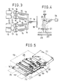
electric field shutter 11 in place of the electrostatic deflectingelectrode 7 of the printing device of Fig. 1. In the printing device of Fig. 2, the direction of dyestuff steam 9 is fixed while the quantity of the dyestuff steam 9 to be jetted toward arecord medium 3 is controlled by theelectric field shutter 11. - Different types of printing devices are disclosed in Japanese Patent Laid-Open No. 57-1771. In the printing devices, dyestuffs of a plurality of colors are heated in individual tanks to produce steam of the dyestuffs, and the steam of the multi-color dyestuffs is collected into a single stream and jetted from a single nozzle. One of such printing devices is shown in Fig. 3. In particular, sublimable dyestuff inks of four colors of yellow, cyan, magenta and black are supplied into an
ink jet nozzle 14 viapipe conduits 13 by individual pressurizing means 12 such as pumps. There, the dyestuff inks are heated by individual heating means 15 such as nichrome wires so that they sublime into dyestuff steam. The dyestuff steam is excited byelectromechanical converters 16 and then jetted asink gas particles 18 from asingle orifice 17 toward arecord medium 19. In this instance, heating of the dyestuff inks is controlled by a heating signal generating device to control the quantities of the dyestuff steam to be produced for the different colors, and the color adjustment is thus made by mixing of the controlled quantities of the steam of the dyestuffs of the different colors. - A further type of printing device is disclosed in Japanese Patent Laid-Open No. 59-22759 and shown in Fig. 4. In particular, the printing device shown includes 3
sublimable dyestuff bars 21 of different colors mounted in anozzle 20, and alaser beam source 22 and alens 23 provided along the direction of an axis of thenozzle 20. Anair system 24 is provided and is opened to thenozzle 20. Thelens 23 is shifted to that a laser beam may be condensed and irradiated upon a desired one of the 3 colorsublimable dyestuff bars 21 to produce steam of the dyestuff. The dyestuff steam thus produced is jetted from an end of thenozzle 20 by compressed air from theair system 24 so that it sticks to arecord medium 25. - Problems of the conventional printing devices described above will now be described. At first, in the case of the arrangement disclosed in Japanese Patent Publication No. 56-2020 mentioned first, there is a problem that the flow rate of dyestuff steam jetted from the nozzle is low and the jetting speed is also low because the pressure of steam of the sublimable dyestuff is low. Further, a high temperature is required in order to raise the steam pressure of dyestuff steam, and a complicated device is required in order to attain such a high temperature. Besides, it is difficult itself to charge molecules of dyestuff steam with electricity without causing dissolution thereof in the atmospheric air.
- Subsequently, in the case of the arrangement disclosed in Japanese Patent Laid-Open No. 57-1771, the ratio of the dyestuff included in a predetermined volume is low because the steam pressure of dyestuff steam is low. Accordingly, in order for the dyestuff to be jetted by an amount required for recording of a picture image, an electromechanical converter having a high air feeding capacity must be used, which makes the printing device complicated and expensive.
- Further, in the case of the arrangement of Japanese Patent Laid-Open No. 59-22759, there is a problem that the printing device is expensive and complicated because an optical system must be provided while jetting of dyestuff steam by a sufficient amount can be attained by pessurization by the air system even if the steam pressure of dyestuff steam is low.
- It is a first object of the present invention to provide a printing device wherein dyestuff steam can be jetted by a sufficiently high flow rate from a nozzle.
- It is a second object of the present invention to provide a printing device which can print at a high speed.
- It is a third object of the present invention to provide a printing device wherein the quality of printing can be made uniform.
- It is a fourth object of the present invention to provide a printing device which is simple in structure.
- It is a fifth object of the present invention to provide a printing device wherein the overall size can be reduced.
- It is a sixth object of the present invention to provide a printing device wherein choking of a nozzle can be prevented.
- It is a seventh object of the present invention to provide a printing device which is superior in durability.
- In order to attain the objects, according to the present invention, there is provided a printing device, comprising a dyestuff case defining a dyestuff chamber for containing a sublimable dyestuff therein, a heating means for heating the sublimable dyestuff to sublime to form steam of the dyestuff, a pressurizing means for flowing gas into the dyestuff steam to pressurize the dyestuff steam to form pressurized dyestuff steam, a nozzle plate communicating in a closing up relationship with the dyestuff case and having a nozzle formed therein for jetting the pressurized dyestuff steam toward a record medium, a valve disposed in an opposing relationship to the nozzle for opening and closing the nozzle, a valve beam having a deformable portion which carries the valve thereon and moves, when deformed, the valve into or out of contact with the nozzle, and an electrode plate located in an opposing relationship to the valve and in an isolated relationship from the valve and the pressurized dyestuff steam for providing a difference in potential with reference to the valve to produce an electrostatic force relative to the valve to displace the valve toward the nozzle.
- With the printing device, a voltage is applied between the electrode plate and the valve beam in response to a picture image signal, and when a picture point is to be formed, a predetermined gap is provided between the valve and the nozzle in order to permit the pressurized dyestuff steam to be jetted from the nozzle, but when a picture point is not to be formed, an electrostatic force is generated between the electrode plate and the valve beam to cause the valve to close the nozzle to interrupt jetting of the pressurized dyestuff steam. By controlling the electrostatic force between the electrode plate and the valve beam in this manner, jetting of the dyestuff steam from the nozzle is controlled to selectively form picture points on a record sheet to print a character or figure.
- It is to be noted that since the electrode plate is provided in an isolated relationship from the valve and the pressurized dyestuff steam which presents a high pressure at a high temperature, the performance at an initial stage is maintained in use for a long period of time, and the printing device is superior in durability.
-
- Fig. 1 is a vertical sectional side elevational view showing an exemplary one of conventional printing devices;
- Fig. 2 is a vertical sectional side elevational view showing another exemplary one of conventional printing devices;
- Fig. 3 is a plan view showing a further exemplary one of conventional printing devices;
- Fig. 4 is a vertical sectional side elevational view showing a still another exemplary one of conventional printing devices;
- Fig. 5 is a perspective view of an entire printing device showing a first embodiment of the present invention;
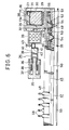
- Fig. 6 is a vertical sectional front elevational view of a jetting head;
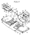
- Fig. 7 is a fragmentary perspective view of the jetting head of Fig. 6;
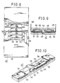
- Fig. 8 is a plan view, partly broken, of the jetting head of Fig. 6;
- Fig. 9 is a vertical sectional side elevational view of the jetting head of Fig. 8;
- Fig. 10 is a perspective view of part of the jetting head of Fig. 8;
- Figs. 11 to 32 show an example of process of producing a jetting control valve, and Fig. 11 is a perspective view of a substrate;
- Fig. 12 is a side elevational view of the substrate of Fig. 11;
- Fig. 13 is a perspective view showing the substrate after completion of a nozzle pattern forming step;
- Fig. 14 is a side elevational view of the substrate of Fig. 13;
- Fig. 15 is a perspective view showing the substrate after completion of a nozzle plate forming step;
- Fig. 16 is a vertical sectional side elevational view of the substrate of Fig. 15;
- Fig. 17 is a perspective view showing the substrate after completion of a first insulator layer forming step;
- Fig. 18 is a vertical sectional side elevational view of the substrate of Fig. 17;
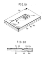
- Fig. 19 is a perspective view showing the substrate after completion of an electrode pattern forming step;
- Fig. 20 is a vertical sectional side elevational view of the substrate of Fig. 19;
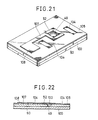
- Fig. 21 is a perspective view showing the substrate after completion of an electrode plate forming step;
- Fig. 22 is a vertical sectional side elevational view of the substrate of Fig. 21;
- Fig. 23 is a perspective view showing the substrate after completion of a second insulator layer forming step;
- Fig. 24 is a vertical sectional side elevational view of the substrate of Fig. 23;
- Fig. 25 is a perspective view showing the substrate after completion of a spacer forming step;
- Fig. 26 is a vertical sectional side elevational view of the substrate of Fig. 25;
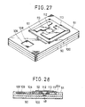
- Fig. 27 is a perspective view showing the substrate after completion of a valve beam pattern forming step;
- Fig. 28 is a vertical sectional side elevational view of the substrate of Fig. 27;
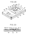
- Fig. 29 is a perspective view showing the substrate after completion of a valve beam forming step;
- Fig. 30 is a vertical sectional side elevational view of the substrate of the substrate of Fig. 29;
- Fig. 31 is a perspective view showing the substrate after completion of a separating step;
- Fig. 32 is vertical sectional side elevational view of the substrate of Fig. 31;
- Fig. 33 is a vertical sectional side elevational view showing a nozzle in an open condition in which dyestuff steam is jetted therefrom;
- Fig. 34 is a vertical sectional side elevational view showing the nozzle in a closed condition;
- Fig. 35 is a vertical sectional side elevational view of a printing device showing a second embodiment of the present invention;
- Fig. 36 is a front elevational view of the printing device of Fig. 35;
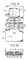
- Fig. 37 is a plant view of a printing device, partly broken, showing a third embodiment of the present invention;
- Fig. 38 is a vertical sectional side elevational view of the printing device of Fig. 37;
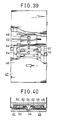
- Fig. 39 is a plan view of a printing device, partly broken, showing a fourth embodiment of the present invention;
- Fig. 40 is a vertical sectional side elevational view of the printing device of Fig. 39;
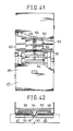
- Fig. 41 is a plan view of a printing device, partly broken, showing a fifth embodiment of the present invention;
- Fig. 42 is a vertical sectional side elevational view of the printing device of Fig. 41;
- Fig. 43 is a plan view of printing device, partly broken, showing a sixth embodiment of the present invention;
- Fig. 44 is a plan view of a printing device, partly broken, showing a seventh embodiment of the present invention; and
- Fig. 45 is a vertical sectional side elevational view of the printing device of Fig. 44.
- A first preferred embodiment of the present invention will be described below with reference to Figs. 5 to 34. In the present embodiment, a printing device is designed for color printing with 3 colors. The printing device includes a flattened
body case 73, and apaper tray 71 provided at a rear portion of thebody case 73 for receiving thereon a plurality of record sheets ofpaper 59 as record media. A dischargingport 74 is provided at a front portion of thebody case 73 for discharging such apaper sheet 59 therethrough. Adischarge tray 75 is mounted adjacent the dischargingport 74. Three jetting heads 45 are provided within thebody case 73. The jetting heads 45 are generally of such a structure that dyestuff steam is jetted from a large number ofnozzles 49 which are provided in an array over the entire width of therecord sheet 59. More particularly, the jetting heads 45 are of a structure wherein asublimable dyestuff 30 contained in adyestuff case 26 is heated by aheater 29 serving as a heating means to produce steam of thedyestuff 30, and air is flowed into the dyestuff steam and is pressurized by a pressurizingpump 34 serving as a pressurizing means to produce pressurized dyestuff steam to be subsequently jetted from thenozzle 49. It is to be noted that each of thenozzles 49 is opened or closed by avalve 54 to control jetting pressurized dyestuff steam. One of the jetting heads 45 serves as ahead 68 for cyan, another one as ahead 69 for yellow, and the remaining one as ahead 70 for magenta, and theheads sublimable dyestuffs 30 of the colors of cyan, yellow and magenta, respectively. - Subsequently, structures of the individual components will be described in detail. At first, the
dyestuff case 26 includes acase 27 substantially in the form of a parallelepiped which is open at the top thereof, and acap 28 for closing the top opening of thecase 27, and thus defines a dyestuff chamber 26a therein. Theheater 29 serving as a heating means is embedded in a bottom wall of thecase 27, and adyestuff cartridge 31 in which thesublimable dyestuff 30 in the solid state is filled is removably mounted in thecase 27. Thedyestuff cartridge 31 includes acartridge body 76 in the form of a casing in which thesublimable dyestuff 30 is contained, and a holdingplate 77 having a large number of communicatingholes 77a formed therein is placed on thesublimable dyestuff 30. Aninflow port 32 is formed in a side wall of thecase 27, and afilter 33 is mounted on the side wall of thecase 27. The pressurizingpump 34 is connected to thefilter 33. In particular, ayoke 35 is fixed by a fixing means not shown and includes acore 36 and apermanent magnet 37 provided thereon. Thepermanent magnet 37 is disposed around the centrally locatedcore 36. Apiston 39 having acoil 38 wound thereon is mounted for axial movement on thecore 36 and fitted in acylinder 40 connected to thefilter 33. Thecylinder 40 has provided thereon aninflow valve 41 in the form of a check valve for permitting gas to flow into thecylinder 40 from the outside, and anoutflow valve 42 in the form of a check valve for permitting gas to be introduced from thecylinder 40 into thefilter 33. Amagnet valve 43 is interposed between theinflow valve 42 and thefilter 33. - An
inflow port 44 is formed in the bottom wall of thecase 27 and communicated with aflow path 46 formed in a corresponding one of the jetting heads 45. Theflow path 46 is formed from a jettingcontrol valve 47 constituting the jettinghead 45 and avessel 48 secured to the jettingcontrol valve 47. The sectional area of theflow path 46 is sufficiently great comparing with the area of an opening of a nozzle which will be hereinafter described. Therefore, the speed of dyestuff steam flowing in the flow path is relatively low, and accordingly the pressure loss is low. Further, even where a plurality of nozzles are involved, the pressure difference from the external air is constant for each nozzle, and the jetting characteristics are made uniform. - The jetting
control valve 47 includes anozzle plate 50 having formed therein a plurality ofnozzles 49 each of which has a inner face of a spherical shape , anelectrode plate 52 embedded in aninsulator layer 51, avalve beam 55 havingdeformable portions 53 at which thevalves 54 are formed, and aprotective film 56 formed on theinsulator layer 51. - The
nozzle plate 50,valve beam 55 andelectrode plate 52 are made of nickel which is superior in heat resisting property and also in dyestuff resisting property while theinsulator layer 51 is made of polyamide which is superior in heat resisting property. Theprotective layer 56 is provided to protect theinsulator layer 51 so that the polyimide may not be dyed by dyestuff steam at a high temperature which may deteriorate the insulation of theinsulator layer 51, and a ceramic material such as SiO₂, Al₂O₃ or Si₃N₄ or a composition represented by any of these substances is used for theprotective layer 56. - The
valve beam 55 is in the form of a beam of the opposite end supported type, and each of thedeformable portions 53 is formed in such a manner as to project in a direction perpendicular to the longitudinal direction of thevalve beam 55 from a central portion of thevalve beam 55. Besides, thedeformable portion 53 is formed with a reduced thicknesss at portions near the opposite ends thereof so as to provide an elastic force by twisting and with the intention of assuring sufficient deformation of thedeformable portion 53 by a low voltage. - The
electrode plate 52 is connected to leadterminals 58 adjacent plate taking outports 57. Thelead terminals 58 are led externally while maintaining the closing up of theflow path 46 and are connected to a positive side terminal of a drivingpower source 79 via aswitch 78 as shown in Figs. 33 and 34. Thevalve beam 55 is connected to the ground G outside while maintaining the closing up of theflow path 46. A negative side terminal of the drivingpower source 79 is connected to a junction between thevalve beam 55 and the ground G. - It is to be noted that
reference numeral 59 denotes a record sheet mentioned hereinabove. - Here, an example of process of producing the jetting
control valve 47 will be described with reference to Figs. 11 to 32. Since the following description with reference to Figs. 11 to 32, however, is given mainly of a process of producing the jettingcontrol valve 47, only general description will be given of any other component of the printing device. Therefore, a jetting control valve produced by the process of Figs. 11 to 32 is shown different in configuration from the jettingcontrol valve 47 of the present embodiment. - At first, such as
substrate 100 as shown in Figs. 11 and 12 is prepared. Thesubstrate 100 is formed, for example, either from a metal plate such as a stainless steel plate the surface of which is finished into a surface of a mirror by polishing or from a glass plate which has a metal film formed on a surface thereof by a suitable means such as vapor deposition. The surface of thesubstrate 100 is preferably formed from a metal material which has a low adhering property to nickel. From this point of view, a stainless steel plate is suitable for the surface of thesubstrate 100. - Figs. 13 and 14 show the
substrate 100 after it has passed a nozzle pattern forming step. At the step, a photo-resistlayer 101 is formed on a surface of thesubstrate 100 and is exposed to light to effect development to form a pattern corresponding to a nozzle. - Figs. 15 and 16 show the
substrate 100 after it has further passed a first nozzle plate forming step. At the step, ametal film 102 is formed on the surface of thesubstrate 100 and the photo-resistlayer 101 is removed to form anozzle plate 50 which has anozzle 49 formed therein. In this instance, since themetal film 102 covers over around the photo-resistlayer 101, thenozzle 49 presents a trumpet-like configuration wherein the diameter thereof gradually increases toward a surface of thenozzle plate 50. It is a matter of course that thenozzle 49 corresponds to the location from which the photo-resistlayer 101 is removed. Themetal plate 102 is formed by nickel plating using a sulfamic acid nickel bath in order to improve the heat resisting property and the durability. - Figs. 17 and 18 show the
substrate 100 after is has further passed a first insulator layer forming step. At the step, afirst insulator layer 105 is formed on a surface of thenozzle plate 50 such that anopening 103 and another pair ofopenings 104 are formed at a portion thereof corresponding to thenozzle 49 and at a pair of other predetermined portions thereof, respectively. Thefirst insulator layer 105 is formed by forming a layer of photosensitive polyimide on the surface of thenozzle plate 50 and then by exposing the layer to light of a pattern for theopenings first insulator layer 105 is about 10 microns. - Figs. 19 and 20 show the
substrate 100 after it has further passed an electrode pattern forming step. At the step, a photo-resistlayer 106 is formed on a surface of thefirst insulator layer 105 around a location opposing to thenozzle 49. - Figs. 21 and 22 show the
substrate 100 after it has further passed an electrode plate forming step. At the step, ametal film 107 is formed on a portion of the surface of thefirst insulator layer 105 on which the photo-resistlayer 106 is not formed and then the photo-resistlayer 106 is removed from theinsulator layer 105 to form anelectrode plate 52. A connectingportion 108 to be connected to thelead terminal 58 described above is formed at part of theelectrode plate 52 and located at the electrode plate taking outport 57 described above. Since themetal film 107 is plated on thefirst insulator layer 105 which is an insulating substance, it is formed by non-electrolytic nickel plating to apply a conductive layer having a high adhering property to thefirst insulator layer 105 and then by nickel plating to prevent corrosion. It is to be noted that the latter nickel plating may be effected using a sulfamic acid nickel bath. - Figs. 23 and 24 show the
substrate 100 after it has further passed a second insulator layer forming step. At the step, asecond insulator layer 110 is formed on the surfaces of thefirst insulator layer 105 and theelectrode plate 52 such thatopenings opening 109 may be formed in portions of thesecond insulator layer 110 corresponding to theopenings first insulator layer 105 and the connectingportion 108 of theelectrode plate 52, respectively. Thesecond insulator 110 has a thickness of about 10 microns. Thesecond insulator layer 110 is formed by applying photosensitive polyimide in the liquid state to the surfaces of thefirst insulator layer 105 and theelectrode plate 52 and then by exposing, after drying, the polyimide layer to light of a pattern for theopenings second insulator layer 110 is heated so as to unite the same with thefirst insulator layer 105 to make theinsulator layer 51. - Figs. 25 and 26 show the
substrate 100 after it has further passed a spacer forming step. At the step, aspacer 111 is formed by sputtering copper on a surface of theinsulator layer 51 including a location opposing to thenozzle 49 and an area around the location using a suitable masking. The thickness of thespacer 111 is about 20 microns. Accordingly, thespacer 111 is formed on a surface of theinsulator layer 51 and inner faces of thenozzle 49 and theopenings recess 112 having a similar configuration to the inner face of theopenings 103 is formed at a portion of theopening 103 of thespacer 111. - Figs. 27 and 28 show the
substrate 100 after it has further passed a valve beam pattern forming step. At the step, a photo-resistlayer 113 is formed on a surface of a portion of thespacer 111 other than a portion opposing to the nozzle 49 (a portion opposing to the recess 112) and a peripheral portion of thespacer 111. - Figs. 29 and 30 show the
substrate 100 after it has further passed a valve beam forming step. At the step, ametal film 114 is formed on the portion of the surface of thespacer 111 on which the photo-resistlayer 113 is not formed in order to form asupport frame 115 of a square profile and avalve beam 55 which has opposite ends connected contiguously to thesupport frame 115. The thickness of themetal film 114 is about 10 microns. Themetal film 114 is formed by nickel plating and is filled also in theopenings 104. Accordingly, the opposite ends of thevalve beam 55 are connected contiguously to thenozzle plate 50 by way of thesupport frame 115. Further, thevalve beam 55 has a crank-likedeformable portion 53 formed thereon which is projected in a direction perpendicular to the length thereof, and since thedeformable portion 53 of thevalve beam 55 is opposed to therecess 112, avalve 54 which extends along an inner face of therecess 112 is formed at thedeformable portion 53. - Figs. 31 and 32 show a semi-completed jetting control valve after it has passed a separating step. At the step, a central portion of the
spacer 111 is removed by etching, and thesubstrate 100 is exfoliated from thenozzle plate 50. Upon etching of thespacer 111, an ammonia-alkali etchant which has a pH value biased to the alkali side is used so that it may not etch any other metal film. Accordingly, the clearance between an outer circumferential of thevalve 54 and inner circumferential faces of theopenings 103 and thenozzle 49 can be made uniform after the central portion of thespacer 111 has been removed. Further, since thesubstrate 100 is formed from a stainless steel plate while thenozzle plate 50 is made of nickel, they can be exfoliated readily from each other. - It is to be noted that while the process of producing the jetting
control valve 47 described above does not include a step of forming theprotective layer 56, theprotective layer 56 is formed on a surface of theinsulator layer 51 after completion of the second insulator layer forming step illustrated in Figs. 23 and 24 before the spacer forming step illustrated in Figs. 25 and 26. Theprotective layer 56 is formed by forming a ceramic material into a thin film by a thin film forming technique. - In this manner, the jetting
control valve 47 can be produced finely with a high degree of accuracy by a thin film forming technique or photo-lithography, and a jetting control valve array including a large number ofsuch nozzles 49 can be produced with a high degree of density. Further, sincesuch nozzles 49 can be formed as a unitary block, an adjusting operation and an assembling operation can be omitted. - Further, nickel which is used in this instance is plated using a non-glazing sulfamic acid nickel bath in which a glazing agent is not used. Thus, by raising the purity of deposited nickel, the corrosion resisting property against dyestuff steam, the heat resisting property, and the durability at a high temperature can be improved.
- It is to be noted that the process of producing the jetting
control valve 47 following the steps described above will be hereinafter referred to as a process consisting principally of photo-electroforming. - With such a construction as described above, as the
heater 29 is energized, thesublimable dyestuff 30 within thedyestuff case 26 is heated to sublime into dyestuff steam. Then, as thecoil 38 is energized, thepiston 39 is moved to feed air within thecylinder 40 into thedyestuff case 26 via theinflow valve 42 and thefilter 33 so that the pressurized dyestuff is supplied from theoutflow port 44 into theflow path 46. In this instance, the pressurized gas is purified by thefilter 33. - Then, as a predetermined voltage is applied between the
electrode plate 52 and thevalve beam 55 from the drivingpower source 79, an electrostatic force is applied to thevalve beam 55 which is normally set in a position in which thevalve 54 is spaced away from thenozzle 49 by an elastic force of thevalve beam 55 itself so that thevalve beam 55 is moved to a stand-by position in which it closes thenozzle 49 as shown in Fig. 34. This principle is quite the same as the principle described in an article entitled "Dynamic Mircomechanics on Silicon: Techniques and Devices" by KURT E. PATERSEN published in "IEEE TRANSACTIONS ON ELECTRON DEVICES, VOL. ED-25, NO. 100, OCTOBER 1978'" annexed to the documents of the present patent application. After such stand-by of thenozzle 49 in the closing condition, as the voltage between theelectrode plate 52 and thevalve beam 55 is controlled in response to a picture image signal by theswitch 78, thevalve 54 opens thenozzle 49 as shown in Fig. 33. Consequently, the pressurized dyestuff steam within theflow path 46 is jetted from thenozzle 49 to form a picture point on therecord sheet 59. Thus, a character or figure is printed with a group of such picture points formed in this manner. Besides, in the present embodiment, since the jetting heads 45 are provided for the three colors of cyan, yellow and magenta, acolor picture image 72 can be formed on therecord sheet 59. Naturally, a continuous line can be printed by continuously jetting the dyestuff steam because there is relative movement between thenozzle 49 and therecord paper 59 as a manner of printing. - Now, a condition for the
valve 54 to close thenozzle 49, a condition for thevalve 54 to open thenozzle 49, and a natural frequency fb of thevalve beam 55 will be described. Here,
ε₀ : dielectric constant of vacuum
V : voltage applied betweenvalve beam 55 andelectrode plate 52
ρ : density ofvalve beam 55
E : Young's modulus ofvalve beam 55
ℓ : length ofvalve beam 55
w : width ofvalve beam 55
t : thickness ofvalve beam 55
D : diameter ofnozzle 49
I : second moment of area ofvalve beam 55
P : difference in pressure between inside and outside of jettinghead 45 - It is to be noted that a following equation stands here.

valve 54 to close thenozzle 49 is provided by a following expression:
valve 54 to open thenozzle 49 is provided by a following expression:
valve beam 55 is provided by a following expression:
- Here, under the condition of
ε₀ = 8,854 x 10⁻¹² (F/m)
for example, following values were set:
V = 300 (V)
E = 2.1 x 10¹¹ (Pa)
ρ = 8902 (kg/m³)
ℓ = 4.0 x 10⁻³ (m)
w = 200 x 10⁻⁶ (m)
t = 10 x 10⁻⁶ (m)
D = 50 x 10⁻⁶ (m)
P = 1000 (Pa)
Those values were substituted into the expressions (1), (2) and (3) above. Thus, a condition for thevalve 54 to close thenozzle 49, that is, the expression (1) becomes
7.969 x 10⁻⁴ > 4.2 x 10⁻⁴
while a condition for thevalve 54 to open thenozzle 49, that is, the expression (2) becomes
1.963 x 10⁻⁶ < 2.1 x 10⁻⁴
Accordingly, it can be seen that the above listed values meet the two conditions. Further, a natural frequency fb of thevalve beam 55 is calculated in accordance with the equation (3) above. Thus,
fb =3.12 x 10³ (Hz) - However, it is apparently seen from the equation (3) that the natural frequency fb of the
valve beam 55 can be readily set by changing the shape, dimensions and components of thevalve beam 55. Accordingly, driving of thevalve beam 55 at a high frequency can be realized readily by setting dimensions and so on of thevalve beam 55 in accordance with the equation (3) above. Consequently, printing at a high speed can be attained by opening and closing of thevalve 54 at a high speed. Further, control of the opening and closing times of thevalve 54 at more than 2 stages is enabled without a considerable delay of the printing speed, and picture points can be indicated in multi-stages. Consequently, apicture image 72 of a color near to a natural color can be attained together with a high color developing property ofsublimable dyestuff 30. - Meanwhile, it is apparent from the expressions (1) and (2) that if the voltage V applied between the
electrode plate 52 and thevalve beam 55 changes, also the amount of movement of thevalve 54 changes. Therefore, by controlling the applied voltage V, it is possible to suitably control the amount of movement of thevalve 54 to adjust the degree of opening of thenozzle 49 to effect control of the flow rate of dyestuff steam to be jetted. - Further, in the pressurizing
pump 34, thecoil 38 is held in a normally energized condition so that thepiston 39 may be normally acted upon by a fixed electromagnetic force. Consequently, the pressure of the dyestuff steam within theflow path 46 is maintained constant whether thenozzles 49 are open or closed. Particularly, where theflow path 46 is set to have a somewhat great volume as in the present embodiment, the fixed pressure of the dyestuff steam is maintained more effectively. Theoretically, the pressure of the dyestuff steam at thenozzles 49 is maintained constant without fail if theflow path 46 which communicates with all of thenozzles 49 is provided. Actually, however, the theory cannot apply strictly because thenozzles 49 are opened and closed at a high speed or by some other reasons. Thus, if the volume of theflow path 46 is great to some degree as in the present embodiment, the pressure within theflow path 46 is not influenced very much by jetting of the dyestuff steam by opening and closing of thenozzles 49, which contributes to maintenance of the constant pressure condition. - It is to be noted that, when the main power source is to be interrupted to stop printing, the
magnet valve 43 is opened to allow the pressurized dyestuff steam within theflow path 46 and thedyestuff case 26 to flow back to stick to thefilter 33, and when the pressure of the dyestuff steam is dropped, the application of the voltage between theelectrode plate 52 and thevalve beam 55 is stopped. Consequently, there is no outflow of the dyestuff steam from thenozzle 49. Further, since thesublimable dyestuff 40 sticking to various portions will sublime again if it receives heat by some heating means, it can be used again and will not cause choking at a communicating portion. - Further, by the process of production of the jetting
control valve 47 consisting principally of photo-electroforming, thenozzles 49,valves 54 and so on can be readily produced finely with a high degree of accuracy, and a color picture image of the equal quality to that of a conventional silver salt photograph can be obtained together with the aforementioned multi-stages. - In the meantime, from another point of view, since an article having a large number of
equivalent nozzles 49 can be produced readily by a thin film forming technique, elongation of a nozzle array can be made readily, and an increase of the area of a picture image to be obtained is enabled. - In addition, since the
electrode plate 52 is embedded in theinsulator layer 51, it is held in an isolated condition from thevalve 54 and the pressurized dyestuff steam which presents a high pressure at a high temperature. Accordingly, the deterioration of theelectrode plate 52 is little and theelectrode plate 52 is superior in durability in use for a long period of time. - It is to be noted that while the gas utilized for pressurization is described to be air in the present embodiment, any other gas which is ready to form a picture point on the
record sheet 59 if its is combined with therecord sheet 59 and thesublimable dyestuff 30 such as, for example, steam of ethyl alcohol, a benzoic acid or the like. - Now, a second preferred embodiment of the present invention will be described with reference to Figs. 35 and 36. A printing device of the present invention has a construction suitable for a so-called serial head wherein the direction of movement of a jetting
head 45 makes a main scanning direction while the direction of movement of arecord sheet 59 makes an auxiliary scanning direction, and a nozzle array for forming a picture image extends in a direction perpendicular to the main scanning direction, and wherein a jettingcontrol nozzle 47 is directly mounted on adyestuff case 26. Accordingly, a spacing within thedyestuff case 26 makes aflow path 46 for dyestuff steam. Construction of the remaining part of the printing device is quite similar to that of the first embodiment described hereinabove. - With such a construction, jetting of dyestuff steam from a
nozzle 49 is controlled by movement of avalve beam 55 to print a character or figure. In this instance, although thevalve beam 55 is located within thedyestuff case 26, since heat is transmitted from aheater 29 to anozzle plate 50 made of nickel so that the temperature of thenozzle plate 50 is raised, there is no possibility that thesublimable dyestuff 40 may stick to a portion around thenozzle 49 to cause choking of thenozzle 49 portion. Further, if choking should be caused at thenozzle 49 portion by sticking thereto of thesublimable dyestuff 30, energization of theheater 29 upon starting of re-use of the printing device will cause sublimation of the stickingsublimable dyestuff 30, and hence the printing device will not substantially suffer from choking. - Subsequently, a third preferred embodiment of the present invention will be described with reference to Figs. 37 and 38. It is to be noted that like parts or components are denoted by like reference numerals to those of the first embodiment and overlapping description of the same will be omitted herein (this also applies to the following embodiments described hereinbelow). A printing device of the present embodiment has a construction suitable for a so-called line head wherein a nozzle array extends in a direction perpendicular to the direction of movement of a
record sheet 59. A pair ofheaters 61 in the form of strings serving as a choking preventing heating means are mounted in avessel 48 and extend in a longitudinal direction of thevessel 48. - Accordingly, the
heaters 61 will heat over the entire length of thevessel 48 to maintain a uniform temperature over anentire jetting head 45, thereby preventing solidification of dyestuff steam and choking of portions aroundnozzles 49 caused by sticking of the dyestuff to the portions. Accordingly, it is made possible to elongate the jettinghead 45. - It is to be noted that where the
vessel 48 is made of a ceramic or plastic material, theheaters 61 can be mounted in thevessel 48 in an integral relationship by molding, or where thick film printing is available, a resistor element can be printed in a pattern for use as a heating means. The latter means may be employed even where thevessel 48 is made of a metal material, and by the means, the number of parts can be reduced by integration of thevessel 48 and theheaters 61. - Now, a fourth embodiment of the present invention will be described with reference to Figs. 39 and 40. A printing device of the present invention is designed to prevent choking of a line head similarly as in the third embodiment described above, and a
heat generating member 62 serving as a choking preventing heating means is layered in an integral relationship on anozzle plate 50 of a jettingcontrol valve 47 and is energized when printing is to be effected. In this instance, since theheat generating member 62 can be provided aroundnozzles 49, the efficiency in prevention of choking of the heating means is improved comparing with the third embodiment described above. - Further, the
heat generating member 62 is produced with a high degree of accuracy without complicating the production procedure because only a heat generating member layering step must be added to a layering step for the jettingcontrol valve 47. It is to be noted that the location at which theheat generating member 62 is formed is not limited to such a location as shown in Figs. 39 and 40 and may otherwise be a location, for example, on a surface of thenozzle plate 50 or between thenozzle plate 50 and aninsulator layer 51. - A fifth preferred embodiment of the present invention will now be described with reference to Figs. 41 and 42. A printing device of the present embodiment is designed such that an
electrode plate 52 is utilized as a heat generating member. In particular, the opposite ends of theelectrode plate 52 are connected asterminals 63 to aheating power source 80, and the width of an outer periphery of anozzle 49 is reduced to form aheat generating portion 64 as a choking preventing heating means in order to improve the efficiency in generation of heat. More particularly, a portion of theelectrode plate 52 opposing to thenozzle 49 is removed in the shape of a regular square to make a thin material shape wherein a narrow portion is elongated to reduce the area of an outer periphery of thenozzle 49 to form aheat generating portion 64. By the construction, the electric resistance is increased at the outer periphery of thenozzle 49 so that thenozzle 49 functions as a heat generating member. In this instance, since nickel has a comparatively high specific resistance, it can be used satisfactorily as theheat generating member 64 and can be reduced to practice without changing the process of production of the jettingcontrol valve 47. Further, where higher heat generation is required, the entirety or part of theelectrode plate 52 may be formed from a separate resistor element. - It is an important point in the present embodiment that while a predetermined voltage is applied to the
electrode plate 52 in order to flow electric current required for generation of heat therethrough, the voltage must be of a value of such a degree that it will not have an influence on movement of thevalve beam 55. Opening and closing movement of thenozzle 49 is effected in such a manner as described hereinabove by application of a voltage in response to a picture image signal. - A sixth preferred embodiment of the present invention will be described below with reference to Fig. 43. A printing device of the present invention is designed to cope with elongation of a line head and enables reduction of the number of terminals by a matrix wiring. At first, an
electrode plate 52 corresponding to a nozzle array is divided into first to nth blocks each includingn nozzles 49. Theelectrode plate 52 corresponding tosingle nozzle 49 and avalve beam 55 includes a pair ofelectrode plates 52 which are isolated from each other. Matrix wirings A₁, A₂, A₃, ..., and An for applying a voltage at a time to theelectrode plates 52 on one side one for each block while common connecting lines B₁, B₂, B₃, ..., and Bn are connected to theelectrode plates 52 on the other side for the individual blocks. - With such a construction as described above, when, for example, the nozzle Z₂₁ of the second block is to be opened, the voltage applied between the terminal B₂ and the terminal A₁ is canceled to cause restoration of the
valve beam 55 for the nozzle Z₂₁ to open the nozzle Z₂₁. In this case, thevalve beam 55 is grounded, and the voltage is applied to theelectrode 52 side. Thereupon, since the voltage is canceled at E₂₁A and E₂₁B of theelectrode plates 52, the nozzles Z₂₁ is opened, but thenozzle 49 will not be opened because the voltage is applied to E₂₂A, E₂₃A, ..., and E₂n. Accordingly, in the case of the present embodiment, it is necessary for thevalve beam 55 to be deformed sufficiently to close thenozzle 49 only by application of the voltage to theelectrode plate 52 on one side. In this manner, scanning in opening and closing of the nozzles are performed for the individual blocks. Accordingly, opening and closing of a total number ofn₂ nozzles 49 can be controlled with a total number of 2n terminals, thereby enabling elongation and increase in density of a nozzle train. - A seventh preferred embodiment of the present invention will be described with reference to Figs. 44 and 45. A printing device of the present invention is constituted such that a
vessel 48 is formed in a flattened configuration and anozzle plate 50 is secured to a face of thevessel 48 with each of the opposite sides thereof except valve beams 55 bent into a crank-like shape.Lead wire portions 65 are provided on suchbent portions 66 of thenozzle plate 50. A pair of closing upmembers 67 are provided on the opposite sides of thenozzle plate 50. - Since a projected portion of the nozzle plate is formed only at an intermediate portion, the area exposed to the external air can be reduced, thereby preventing heat from escaping to the external air. In addition to such a heat insulting effect, reduction in size of a jetting
head 45, increase in strength of thenozzle plate 50, improvement in closing up performance and so on are enabled.
Claims (23)
1. A printing device, comprising:
a dyestuff case defining a dyestuff chamber for containing a sublimable dyestuff therein;
heating means for heating the sublimable dyestuff to sublime to form vapour of the dyestuff;
pressurizing means for flowing gas into the dyestuff vapour to pressurize the dyestuff vapour to form pressurized dyestuff vapour;
a nozzle plate communicating in a closing up relationship with said dyestuff case and having a nozzle formed therein for jetting the pressurized dyestuff vapour toward a record medium;
a valve disposed in an opposing relationship to said nozzle for opening and closing said nozzle;
a valve beam having a deformable portion which carries said valve thereon and moves, when deformed, said valve into or out of contact with said nozzle; and
an electrode plate located in an opposing relationship to said valve and in an isolated relationship from said valve and the pressurized dyestuff vapour for providing a difference in potential with reference to said valve to produce an electrostatic force relative to said valve to displace said valve toward said nozzle.
2. A printing device according to claim 1, further comprising a plurality of jetting heats having sublimable dyestuffs or different colors therein, the sublimable dyestuffs of the different colors being selectively jetted to effect color printing.
3. A printing device according to claim 1 or claim 2, wherein said nozzle plate and said valve beam are provided on a side wall of said dyestuff case.
4. A printing device according to claim 3, wherein a plurality of nozzles and a plurality of valves are provided to form a jetting head of the serial type.
5. A printing device according to any preceding claim, further comprising a vessel located on one side of said nozzle plate to cover said valve beam and communicating with said dyestuff chamber to define a flow path for introducing the pressurised dyestuff vapour to said nozzle.
6. A printing device according to claim 5, further comprising a choking preventing heating means embedded in said vessel.
7. A printing device according to claim 1, wherein said heating means is a heater embedded in said dyestuff case.
8. A printing device according to any preceding claim, wherein the gas to be flowed into the dyestuff vapour is air.
9. A printing device according to any one of claims 1 to 7, wherein the gas to be flowed into the dyestuff vapour is ethyl alcohol vapour.
10. A printing device according to any one of claims 1 to 7, wherein the gas to be flowed into the dyestuff vapour is benzoic acid vapour.
11. A printing device according to any preceding claim, wherein said pressurising means is an electromagnetic pump.
12. A printing device according to claim 1, wherein said pressurising means and said dyestuff case are connected to each other via a filter.
13. A printing device according to claim 12, wherein a valve is interposed between said pressurising means and said filter.
14. A printing device according to claim 13, wherein said valve is a magnetically operable valve which is opened when the main power source for said printing device is turned off.
15. A printing device according to claim 1, wherein said nozzle plate and said valve beam are formed by photo-electroforming.
16. A printing device according to claim 15, wherein said electrode plate is embedded in an insulating layer formed on said nozzle plate.
17. A printing device according to claim 15, wherein a large number of nozzles and a large number of valves are disposed in an array.
18. A printing device according to claim 1, wherein said nozzle has a tapering configuration wherein it tapers toward the jetting direction of the pressurized dyestuff steam.
19. A printing device according to claim 1, wherein said electrode is a heating member which serves also as a choking preventing heating means.
20. A printing device according to claim 1, wherein a portion of said electrode plate opposing to said nozzle is removed in a square shape while the remaining portion is formed in an elongated configuration so that it may serve as a heating member.
21. A printing device according to claim 1, wherein a choking preventing heating means is embedded in a portion of said nozzle plate around said nozzle.
22. A printing device according to claim 1, wherein said valve beam is driven with a high frequency.
23. A printing device according to claim 1, wherein said valve is opened once or a plurality of times to form a picture element which is represented in one of different stages.
Applications Claiming Priority (2)
| Application Number | Priority Date | Filing Date | Title |
|---|---|---|---|
| JP69585/87 | 1987-03-24 | ||
| JP62069585A JPH0712679B2 (en) | 1987-03-24 | 1987-03-24 | Printer |
Publications (2)
| Publication Number | Publication Date |
|---|---|
| EP0284282A2 true EP0284282A2 (en) | 1988-09-28 |
| EP0284282A3 EP0284282A3 (en) | 1990-11-22 |
Family
ID=13407048
Family Applications (1)
| Application Number | Title | Priority Date | Filing Date |
|---|---|---|---|
| EP19880302282 Withdrawn EP0284282A3 (en) | 1987-03-24 | 1988-03-16 | Thermal ink jet printer |
Country Status (3)
| Country | Link |
|---|---|
| US (1) | US4864325A (en) |
| EP (1) | EP0284282A3 (en) |
| JP (1) | JPH0712679B2 (en) |
Cited By (7)
| Publication number | Priority date | Publication date | Assignee | Title |
|---|---|---|---|---|
| EP0417673A2 (en) * | 1989-09-11 | 1991-03-20 | Matsushita Electric Industrial Co., Ltd. | Ink recording apparatus |
| EP0593364A2 (en) * | 1992-10-14 | 1994-04-20 | Sony Corporation | Printing device and photographic paper |
| EP0730963A2 (en) * | 1995-03-09 | 1996-09-11 | Sharp Kabushiki Kaisha | Image recording method and apparatus using the same |
| EP0761445A2 (en) * | 1995-09-12 | 1997-03-12 | SHARP Corporation | Image recording device for recording by emitting evaporated ink onto a recording medium |
| EP0784254A2 (en) * | 1995-12-22 | 1997-07-16 | Hahn-Schickard-Gesellschaft Für Angewandte Forschung E.V. | Device for controlling the flow of a liquid |
| EP0791457A2 (en) * | 1996-02-26 | 1997-08-27 | SHARP Corporation | Image forming apparatus provided with ink cartridge preventing deterioration of heater by ink and ink cartridge of the same |
| EP0825024A2 (en) * | 1996-08-21 | 1998-02-25 | Sharp Kabushiki Kaisha | Method and apparatus for image recording by emitting evaporated ink onto a recording medium |
Families Citing this family (2)
| Publication number | Priority date | Publication date | Assignee | Title |
|---|---|---|---|---|
| JPH06115069A (en) * | 1992-09-04 | 1994-04-26 | Xerox Corp | Droplet jet method by acoustic or electrostatic force |
| KR0185329B1 (en) * | 1996-03-27 | 1999-05-15 | 이형도 | Recording method using motor inertia of recording liquid |
Citations (5)
| Publication number | Priority date | Publication date | Assignee | Title |
|---|---|---|---|---|
| EP0112701A2 (en) * | 1982-12-16 | 1984-07-04 | Nec Corporation | Valve element for use in an ink-jet printer head |
| EP0178881A1 (en) * | 1984-10-15 | 1986-04-23 | Dataproducts Corporation | Delivery of phase change ink in ink jet apparatus |
| DE3445720A1 (en) * | 1984-12-14 | 1986-06-19 | Siemens AG, 1000 Berlin und 8000 München | ARRANGEMENT FOR THE EMISSION OF SINGLE DROPLES FROM THE SPLIT OPENINGS OF AN INK WRITING HEAD |
| US4647945A (en) * | 1986-02-06 | 1987-03-03 | Tokyo Electric Co., Ltd. | Image recording method and its apparatus |
| EP0237669A1 (en) * | 1986-03-20 | 1987-09-23 | Tokyo Electric Co., Ltd. | Image recording method and apparatus |
Family Cites Families (2)
| Publication number | Priority date | Publication date | Assignee | Title |
|---|---|---|---|---|
| US3763308A (en) * | 1971-10-20 | 1973-10-02 | Fuji Photo Film Co Ltd | Image reproducing system |
| GB1444094A (en) * | 1973-01-31 | 1976-07-28 | Ici Ltd | Colouration process |
-
1987
- 1987-03-24 JP JP62069585A patent/JPH0712679B2/en not_active Expired - Lifetime
-
1988
- 1988-03-16 EP EP19880302282 patent/EP0284282A3/en not_active Withdrawn
- 1988-03-18 US US07/170,233 patent/US4864325A/en not_active Expired - Fee Related
Patent Citations (5)
| Publication number | Priority date | Publication date | Assignee | Title |
|---|---|---|---|---|
| EP0112701A2 (en) * | 1982-12-16 | 1984-07-04 | Nec Corporation | Valve element for use in an ink-jet printer head |
| EP0178881A1 (en) * | 1984-10-15 | 1986-04-23 | Dataproducts Corporation | Delivery of phase change ink in ink jet apparatus |
| DE3445720A1 (en) * | 1984-12-14 | 1986-06-19 | Siemens AG, 1000 Berlin und 8000 München | ARRANGEMENT FOR THE EMISSION OF SINGLE DROPLES FROM THE SPLIT OPENINGS OF AN INK WRITING HEAD |
| US4647945A (en) * | 1986-02-06 | 1987-03-03 | Tokyo Electric Co., Ltd. | Image recording method and its apparatus |
| EP0237669A1 (en) * | 1986-03-20 | 1987-09-23 | Tokyo Electric Co., Ltd. | Image recording method and apparatus |
Cited By (15)
| Publication number | Priority date | Publication date | Assignee | Title |
|---|---|---|---|---|
| EP0417673A3 (en) * | 1989-09-11 | 1991-10-30 | Matsushita Electric Industrial Co., Ltd. | Ink recording apparatus |
| EP0417673A2 (en) * | 1989-09-11 | 1991-03-20 | Matsushita Electric Industrial Co., Ltd. | Ink recording apparatus |
| EP0593364B1 (en) * | 1992-10-14 | 1998-04-08 | Sony Corporation | Printing device and photographic paper |
| EP0593364A2 (en) * | 1992-10-14 | 1994-04-20 | Sony Corporation | Printing device and photographic paper |
| US5594480A (en) * | 1992-10-14 | 1997-01-14 | Sony Corporation | Printing device and photographic paper |
| EP0730963A2 (en) * | 1995-03-09 | 1996-09-11 | Sharp Kabushiki Kaisha | Image recording method and apparatus using the same |
| EP0730963A3 (en) * | 1995-03-09 | 1997-08-13 | Sharp Kk | Image recording method and apparatus using the same |
| EP0761445A2 (en) * | 1995-09-12 | 1997-03-12 | SHARP Corporation | Image recording device for recording by emitting evaporated ink onto a recording medium |
| EP0761445A3 (en) * | 1995-09-12 | 1997-08-13 | Sharp Kk | Image recording device for recording by emitting evaporated ink onto a recording medium |
| EP0784254A2 (en) * | 1995-12-22 | 1997-07-16 | Hahn-Schickard-Gesellschaft Für Angewandte Forschung E.V. | Device for controlling the flow of a liquid |
| EP0784254A3 (en) * | 1995-12-22 | 1998-05-20 | Hahn-Schickard-Gesellschaft Für Angewandte Forschung E.V. | Device for controlling the flow of a liquid |
| EP0791457A2 (en) * | 1996-02-26 | 1997-08-27 | SHARP Corporation | Image forming apparatus provided with ink cartridge preventing deterioration of heater by ink and ink cartridge of the same |
| EP0791457A3 (en) * | 1996-02-26 | 1998-11-25 | SHARP Corporation | Image forming apparatus provided with ink cartridge preventing deterioration of heater by ink and ink cartridge of the same |
| EP0825024A2 (en) * | 1996-08-21 | 1998-02-25 | Sharp Kabushiki Kaisha | Method and apparatus for image recording by emitting evaporated ink onto a recording medium |
| EP0825024A3 (en) * | 1996-08-21 | 1998-09-30 | Sharp Kabushiki Kaisha | Method and apparatus for image recording by emitting evaporated ink onto a recording medium |
Also Published As
| Publication number | Publication date |
|---|---|
| JPS63233844A (en) | 1988-09-29 |
| JPH0712679B2 (en) | 1995-02-15 |
| US4864325A (en) | 1989-09-05 |
| EP0284282A3 (en) | 1990-11-22 |
Similar Documents
| Publication | Publication Date | Title |
|---|---|---|
| US5825385A (en) | Constructions and manufacturing processes for thermally activated print heads | |
| US6039425A (en) | Ink jet recording method and head | |
| US5850241A (en) | Monolithic print head structure and a manufacturing process therefor using anisotropic wet etching | |
| US5871656A (en) | Construction and manufacturing process for drop on demand print heads with nozzle heaters | |
| JPH10337868A (en) | Magnetic operation ink jet print device and manufacture thereof | |
| EP1657063B1 (en) | Print head, manufacturing method therefor and printer | |
| JP3395974B2 (en) | Bubble jet type inkjet print head | |
| US6045710A (en) | Self-aligned construction and manufacturing process for monolithic print heads | |
| US4864325A (en) | Printing device | |
| EP0763430A2 (en) | CMOS process compatible fabrication of print heads | |
| US6719410B2 (en) | Ink jet head and manufacturing method thereof | |
| JP3551603B2 (en) | Ink jet printer head and ink jet recording apparatus | |
| JPH10501772A (en) | Monolithic printhead heater structure and manufacturing process | |
| EP0771272A1 (en) | Monolithic printing heads and manufacturing processes therefor | |
| WO1996032284A9 (en) | Monolithic printing heads and manufacturing processes therefor | |
| EP0772525A1 (en) | Constructions and manufacturing processes for thermally activated print heads | |
| WO1996032272A1 (en) | Page image and fault tolerance control apparatus for printing systems | |
| EP0765241A1 (en) | A self-aligned construction and manufacturing process for monolithic print heads | |
| JPH0820110A (en) | Thermal ink jet printer | |
| JP2680303B2 (en) | Color inkjet head | |
| EP0765240A1 (en) | Monolithic print head structure and a manufacturing process therefor using anisotropic wet etching | |
| KR200168788Y1 (en) | Ink jetting apparatus | |
| JPH10501774A (en) | Integrated four-color print head |
Legal Events
| Date | Code | Title | Description |
|---|---|---|---|
| PUAI | Public reference made under article 153(3) epc to a published international application that has entered the european phase |
Free format text: ORIGINAL CODE: 0009012 |
|
| AK | Designated contracting states |
Kind code of ref document: A2 Designated state(s): DE FR GB |
|
| 17P | Request for examination filed |
Effective date: 19880906 |
|
| PUAL | Search report despatched |
Free format text: ORIGINAL CODE: 0009013 |
|
| AK | Designated contracting states |
Kind code of ref document: A3 Designated state(s): DE FR GB |
|
| 17Q | First examination report despatched |
Effective date: 19920723 |
|
| STAA | Information on the status of an ep patent application or granted ep patent |
Free format text: STATUS: THE APPLICATION HAS BEEN WITHDRAWN |
|
| 18W | Application withdrawn |
Withdrawal date: 19930108 |