EP0283767B1 - Socket contact for contact devices of the pin and socket type - Google Patents
Socket contact for contact devices of the pin and socket type Download PDFInfo
- Publication number
- EP0283767B1 EP0283767B1 EP88103043A EP88103043A EP0283767B1 EP 0283767 B1 EP0283767 B1 EP 0283767B1 EP 88103043 A EP88103043 A EP 88103043A EP 88103043 A EP88103043 A EP 88103043A EP 0283767 B1 EP0283767 B1 EP 0283767B1
- Authority
- EP
- European Patent Office
- Prior art keywords
- sleeve
- contact
- socket
- slots
- socket contact
- Prior art date
- Legal status (The legal status is an assumption and is not a legal conclusion. Google has not performed a legal analysis and makes no representation as to the accuracy of the status listed.)
- Expired - Lifetime
Links
Images
Classifications
-
- H—ELECTRICITY
- H01—ELECTRIC ELEMENTS
- H01R—ELECTRICALLY-CONDUCTIVE CONNECTIONS; STRUCTURAL ASSOCIATIONS OF A PLURALITY OF MUTUALLY-INSULATED ELECTRICAL CONNECTING ELEMENTS; COUPLING DEVICES; CURRENT COLLECTORS
- H01R13/00—Details of coupling devices of the kinds covered by groups H01R12/70 or H01R24/00 - H01R33/00
- H01R13/02—Contact members
- H01R13/10—Sockets for co-operation with pins or blades
- H01R13/11—Resilient sockets
Definitions
- the present invention has for its object a socket contact for electrical contact devices, of the pin and socket type.
- the socket contact object of the invention is of the type in which, when the pin contact is not inserted, the areas of the socket contact intended to establish the contact with the pin contact are arranged at least approximately according to a family of straight generatrices of a hyperboloid of revolution of one branch.
- Said socket member is obtained by means of a permanent deformation by twisting according to a predetermined angle of a cylindrical hollow body or sleeve of suitable metal, provided with through slots arranged along its cylindrical surface and inclined with respect to the longitudinal axis of said cylindrical body, said twisting being directed in the sense of inclination of the slots.
- a socket contact of such type is disclosed for example in the European patent EP-B1-O 061 587 in the name of the same applicant.
- the problem of the positioning of the zone of maximum reduction of the socket contact in proximity of the inlet of the socket contact itself is solved by providing, in a socket contact of the type above specified, a plurality of slots characterized by the fact of presenting each a lance-head or lanceolate shape, in which the bases of each slot are arranged in proximity of the annular inlet zone of the socket contact.
- a socket contact intended to be the female element in an electric contact device.
- Said socket contact is of the type disclosed for example in the European patent EP-B1-O 061587 in the name of the same applicant, and it is normally obtained starting from a solid bar machined by a machine tool. More precisely in said bar there is obtained a bore 10 suitably flared out at its inlet, so as to define a rectangular circular cylindrical sleeve 1 closed at one base or end. In correspondence with the base ends of the cylindrical sleeve which define annular zones or "rings " 4 and 5, there can be optionally obtained, by machining, two annular projections 104 and 105.
- the socket contact is completed by a hollow appendix 101 serving for the connection (in a known manner) with the terminals of an electrical cable (not shown).
- a hollow appendix 101 serving for the connection (in a known manner) with the terminals of an electrical cable (not shown).
- the socket member is made of any suitable metal or metal alloy for electric conduction. It must be noted that the socket contact according to the present invention may consist only of the cylindrical body of sleeve 1, without the appendix 101 and without the annular projections 104 and 105, as described in another application filed on this same date in the name of the same applicant.
- slots 2 On the cylindrical wall of the sleeve wall there are obtained a plurality of slots 2 arranged along the whole circumference, preferably equispaced. Said slots may be obtained in any suitable manner, for example by machining, with the aid of a double-angle milling cutter (not shown). As it appears from the figures, said slots 2 are inclined with respect to the longitudinal axis of sleeve 1 and define between each other a plurality of strips 3 which are inclined with respect to the longitudinal axis of sleeve 1 of the same inclination angle.
- the slots 2 are characterized by the fact that they present a lance-head or lanceolate shape, with the apex 202 and the base 102 which are both pointed, i.e. with a sharp edge. More particularly, the bases 102 of each slot 2 terminate in the zone of the inlet ring 5 of the sleeve 1. In this manner, each strip 3 defined between two slots 2 does not present a uniform width, but it presents a region of smaller width in proximity of the inlet ring 5.
- Said smaller width of the strip leads to a consequent weakening of the strip itself in said zone, so that, following to the twisting imparted to the sleeve itself, by effecting a relative rotation according to a predetermined angle between the two end rings 4 and 5, there will be obtained a deformation of the strips 3 whereby same will tend to arrange themselves at least approximately according to a family of generatrices of a hyperboloid of one branch, in such a manner that the zone of progressive maximum reduction of the sleeve will be located in proximity of the inlet ring 5 of the sleeve 1 itself.
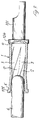
- said feature is particularly advantageous in the case that it is required (either due to standard rules or to functional requirements of the contact) that the electric contact between the socket 1 and the pin 6 (see particularly Figure 3) takes place not beyond a predetermined length of insertion of the pin 6 into the bore of the socket.
- the contact according to the present invention can be also obtained by means of coinage operation, starting from a solid bar, which is subsequently subjected to axial boring.
- the contact 1 according to the present invention can be moreover obtained, in a known manner, starting from punched metal sheets, or also starting from a continuous pipe.
Landscapes
- Connector Housings Or Holding Contact Members (AREA)
- Coupling Device And Connection With Printed Circuit (AREA)
- Manufacturing Of Electrical Connectors (AREA)
- Connecting Device With Holders (AREA)
- Details Of Connecting Devices For Male And Female Coupling (AREA)
- Breakers (AREA)
Abstract
Description
- The present invention has for its object a socket contact for electrical contact devices, of the pin and socket type.
- More precisely, the socket contact object of the invention is of the type in which, when the pin contact is not inserted, the areas of the socket contact intended to establish the contact with the pin contact are arranged at least approximately according to a family of straight generatrices of a hyperboloid of revolution of one branch. Said socket member is obtained by means of a permanent deformation by twisting according to a predetermined angle of a cylindrical hollow body or sleeve of suitable metal, provided with through slots arranged along its cylindrical surface and inclined with respect to the longitudinal axis of said cylindrical body, said twisting being directed in the sense of inclination of the slots. A socket contact of such type is disclosed for example in the European patent EP-B1-O 061 587 in the name of the same applicant.
- In such type of socket contacts there arises the problem (both due to standard rules and to functional requirements of the contact) to obtain that the electric contact between the socket and the pin takes place not beyond a predetermined length of insertion of the pin contact itself inside the bore of the socket contact. According to what disclosed in the cited European patent EP-B1-O 061 587, said problem is solved by obtaining a zone of smaller thickness in the cylindrical sleeve which constitutes the socket contact and thus varying consequently the positioning of the zone of greatest reduction along the sleeve itself. More particularly said variation along of the thickness is obtained by forming the sleeve in such a manner that it presents an outer conicity directed towards the inlet of the said sleeve. This solution of the problem now exposed, although being satisfactory, presents some difficulties due to the necessity of obtaining an outer conicity of the sleeve, particularly in the case of reduced dimensions of the sleeve itself.
- According to the present invention, the problem of the positioning of the zone of maximum reduction of the socket contact in proximity of the inlet of the socket contact itself is solved by providing, in a socket contact of the type above specified, a plurality of slots characterized by the fact of presenting each a lance-head or lanceolate shape, in which the bases of each slot are arranged in proximity of the annular inlet zone of the socket contact.
- The above and other features of the socket contact object of the present invention, and the advantages deriving therefrom, will appear evident from the following description, made by way of non-limiting example, of a preferred embodiment, with reference to the figures of the attached drawings, in which:
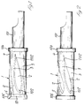
- Figure 1 is a side view, with parts in section, of a socket contact provided with slots according to the invention, prior to the twisting operation.
- Figure 2 is a side view of the socket contact of Figure 1, after the twisting operation.
- Figure 3 is a side view, with parts in section, of the socket contact subsequently to being subjected to twisting, and showing the pin contact while being inserted.
- With reference to Figure 1, there is shown a socket contact intended to be the female element in an electric contact device. Said socket contact is of the type disclosed for example in the European patent EP-B1-O 061587 in the name of the same applicant, and it is normally obtained starting from a solid bar machined by a machine tool. More precisely in said bar there is obtained a
bore 10 suitably flared out at its inlet, so as to define a rectangular circularcylindrical sleeve 1 closed at one base or end. In correspondence with the base ends of the cylindrical sleeve which define annular zones or "rings " 4 and 5, there can be optionally obtained, by machining, twoannular projections hollow appendix 101 serving for the connection (in a known manner) with the terminals of an electrical cable (not shown). Obviously, the shape and size of said connection appendix for the connection with the electric circuit can vary in any known manner which can be easily conceived by a person skilled in the art, depending upon the required connection. The socket member is made of any suitable metal or metal alloy for electric conduction. It must be noted that the socket contact according to the present invention may consist only of the cylindrical body ofsleeve 1, without theappendix 101 and without theannular projections - On the cylindrical wall of the sleeve wall there are obtained a plurality of
slots 2 arranged along the whole circumference, preferably equispaced. Said slots may be obtained in any suitable manner, for example by machining, with the aid of a double-angle milling cutter (not shown). As it appears from the figures, saidslots 2 are inclined with respect to the longitudinal axis ofsleeve 1 and define between each other a plurality ofstrips 3 which are inclined with respect to the longitudinal axis ofsleeve 1 of the same inclination angle. - The
slots 2 are characterized by the fact that they present a lance-head or lanceolate shape, with theapex 202 and thebase 102 which are both pointed, i.e. with a sharp edge. More particularly, thebases 102 of eachslot 2 terminate in the zone of theinlet ring 5 of thesleeve 1. In this manner, eachstrip 3 defined between twoslots 2 does not present a uniform width, but it presents a region of smaller width in proximity of theinlet ring 5. Said smaller width of the strip leads to a consequent weakening of the strip itself in said zone, so that, following to the twisting imparted to the sleeve itself, by effecting a relative rotation according to a predetermined angle between the twoend rings strips 3 whereby same will tend to arrange themselves at least approximately according to a family of generatrices of a hyperboloid of one branch, in such a manner that the zone of progressive maximum reduction of the sleeve will be located in proximity of theinlet ring 5 of thesleeve 1 itself. As it was stated above, said feature is particularly advantageous in the case that it is required (either due to standard rules or to functional requirements of the contact) that the electric contact between thesocket 1 and the pin 6 (see particularly Figure 3) takes place not beyond a predetermined length of insertion of the pin 6 into the bore of the socket. - It is evident that by modifying the shape and/or the zone of maximum width of each
lanceolate slot 2, and consequently the shape of eachstrip 3 defined between twoslots 2, it will be possible to modify the positioning of the point of maximum reduction ofsleeve 1, with corresponding variation of the initial contact point between the pin contact 6 and the interior ofsleeve 1. - The contact according to the present invention can be also obtained by means of coinage operation, starting from a solid bar, which is subsequently subjected to axial boring.
- The
contact 1 according to the present invention can be moreover obtained, in a known manner, starting from punched metal sheets, or also starting from a continuous pipe. - It is therefore to be understood that the invention is not limited to the embodiment which has been above described and illustrated merely by way of example, and that many variations and modifications are possible, without however departing from the scope of the invention as claimed hereinafter.
Claims (6)
- A socket contact for contact devices of the socket and pin type, in which when the pin contact (6) is not inserted the areas of the socket contact intended to establish the contact with the pin contact, upon insertion of same, are arranged at least approximately according to a family of straight generatrices of a hyperboloid of revolution of one branch, said socket contact being obtained by means of deformation by twisting through a predetermined angle of a hollow cylindrical body or sleeve (1) of suitable metal, provided with through slots (2) arranged along its cylindrical surface and inclined with respect to the longitudinal axis of said sleeve (1), said twisting being directed in the sense of inclination of the slots (2), characterized by the fact that, prior to the twisting deformation, each slot presents a lance-head or lanceolate shape, having the base (102) near to the zone of maximum width of the slot and the apex (202) into which terminates the zone of lesser width of the slot itself, the bases (102) of the slots (2) being arranged in proximity of the annular inlet zone (5) of the sleeve (1).
- A socket contact according to claim 1, characterized by the fact that both the base (102) and the apex (202) of each lanceolate slot (2) terminate with sharp edges.
- A socket contact according to claim 1, characterized by the fact that the through slots (2) are obtained by machining, by using a suitable milling cutter and starting from a sleeve (1) obtained from a solid bar, machined and bored, or from a continuous pipe.
- A socket contact according to claim 1, characterized by the fact that the sleeve (1) is obtained starting from metal sheet which is punched and subsequently shaped by bending.
- A socket contact according to claim 4, characterized by the fact that the slots (2) are obtained upon punching of the metal sheet.
- A socket contact according to claim 1, characterized by the fact that the sleeve (1) provided with slots (2) is obtained by means of coinage operations, starting from a solid bar, and with subsequent longitudinal boring.
Priority Applications (1)
| Application Number | Priority Date | Filing Date | Title |
|---|---|---|---|
| AT88103043T ATE75881T1 (en) | 1987-03-25 | 1988-03-01 | SOCKET CONTACT FOR A CONTACT ARRANGEMENT ACCORDING TO THE PLUG AND SOCKET PRINCIPLE. |
Applications Claiming Priority (2)
| Application Number | Priority Date | Filing Date | Title |
|---|---|---|---|
| IT1244787 | 1987-03-25 | ||
| IT8712447A IT1208262B (en) | 1987-03-25 | 1987-03-25 | BUSHING FOR BUSHING AND PIN PLUG CONTACT DEVICES |
Publications (3)
| Publication Number | Publication Date |
|---|---|
| EP0283767A2 EP0283767A2 (en) | 1988-09-28 |
| EP0283767A3 EP0283767A3 (en) | 1990-02-14 |
| EP0283767B1 true EP0283767B1 (en) | 1992-05-06 |
Family
ID=11140268
Family Applications (1)
| Application Number | Title | Priority Date | Filing Date |
|---|---|---|---|
| EP88103043A Expired - Lifetime EP0283767B1 (en) | 1987-03-25 | 1988-03-01 | Socket contact for contact devices of the pin and socket type |
Country Status (10)
| Country | Link |
|---|---|
| US (1) | US4840588A (en) |
| EP (1) | EP0283767B1 (en) |
| JP (1) | JPS63250075A (en) |
| AT (1) | ATE75881T1 (en) |
| CA (1) | CA1300243C (en) |
| CS (1) | CS189688A3 (en) |
| DE (1) | DE3870686D1 (en) |
| IL (1) | IL85655A0 (en) |
| IT (1) | IT1208262B (en) |
| SU (1) | SU1609461A3 (en) |
Families Citing this family (12)
| Publication number | Priority date | Publication date | Assignee | Title |
|---|---|---|---|---|
| US4878863A (en) * | 1988-12-22 | 1989-11-07 | Amp Incorporated | Electrical connector and contact terminal therefor |
| US5653601A (en) * | 1995-07-11 | 1997-08-05 | Molex Incorporated | Terminal socket assembly |
| US6139374A (en) * | 1995-07-25 | 2000-10-31 | Framatome Connectors Interlock Inc. | Connector assembly |
| US6767260B2 (en) * | 2002-02-28 | 2004-07-27 | Qa Technology Company, Inc. | Hyperboloid electrical contact |
| US7021963B2 (en) * | 2002-08-15 | 2006-04-04 | 3M Innovative Properties Company | Electrical contact |
| US20080026645A1 (en) * | 2006-07-26 | 2008-01-31 | Motorola, Inc. | Connector adaptor and method |
| US7931509B2 (en) * | 2009-09-25 | 2011-04-26 | Glen David Shaw | Coaxial fitting contact tube construction |
| DE102010003599A1 (en) * | 2010-04-01 | 2011-10-06 | Lisa Dräxlmaier GmbH | Process for cable assembly and ready-made cable |
| TWM394399U (en) * | 2010-07-20 | 2010-12-11 | Ks Terminals Inc | Water-proof connector and female terminal therein |
| US8888527B2 (en) | 2011-10-25 | 2014-11-18 | Perfectvision Manufacturing, Inc. | Coaxial barrel fittings and couplings with ground establishing traveling sleeves |
| US11051761B2 (en) | 2015-06-15 | 2021-07-06 | Sunnybrook Research Institute | Intravascular imaging catheters and methods of use thereof |
| GB2589061A (en) * | 2019-09-18 | 2021-05-26 | Harwin Plc | Electrical contact and method of manufacturing |
Family Cites Families (5)
| Publication number | Priority date | Publication date | Assignee | Title |
|---|---|---|---|---|
| AT110194B (en) * | 1926-10-25 | 1928-07-10 | Josef Fallosch | Process for the production of elastic connector sleeves. |
| US3314044A (en) * | 1964-12-16 | 1967-04-11 | Albert E Powell | Female electrical connectors |
| JPS5617791A (en) * | 1979-07-23 | 1981-02-19 | Kure Dia:Kk | Cooling method for hydraulic fluid in hydraulically propelled ship |
| DE3267086D1 (en) * | 1981-03-16 | 1985-12-05 | Connei Spa | A socket member for an electrical connector and a method for making same |
| DE3518030C2 (en) * | 1985-05-20 | 1987-03-05 | Multi-Contact AG Basel, Basel | Electrically conductive contact device |
-
1987
- 1987-03-25 IT IT8712447A patent/IT1208262B/en active
-
1988
- 1988-03-01 EP EP88103043A patent/EP0283767B1/en not_active Expired - Lifetime
- 1988-03-01 DE DE8888103043T patent/DE3870686D1/en not_active Expired - Fee Related
- 1988-03-01 AT AT88103043T patent/ATE75881T1/en active
- 1988-03-07 IL IL85655A patent/IL85655A0/en unknown
- 1988-03-07 US US07/164,906 patent/US4840588A/en not_active Expired - Fee Related
- 1988-03-08 CA CA000560851A patent/CA1300243C/en not_active Expired - Lifetime
- 1988-03-14 JP JP63058536A patent/JPS63250075A/en active Pending
- 1988-03-22 SU SU884355370A patent/SU1609461A3/en active
- 1988-03-23 CS CS881896A patent/CS189688A3/en unknown
Also Published As
| Publication number | Publication date |
|---|---|
| EP0283767A3 (en) | 1990-02-14 |
| IT8712447A0 (en) | 1987-03-25 |
| CA1300243C (en) | 1992-05-05 |
| JPS63250075A (en) | 1988-10-17 |
| US4840588A (en) | 1989-06-20 |
| ATE75881T1 (en) | 1992-05-15 |
| IL85655A0 (en) | 1988-08-31 |
| SU1609461A3 (en) | 1990-11-23 |
| DE3870686D1 (en) | 1992-06-11 |
| EP0283767A2 (en) | 1988-09-28 |
| IT1208262B (en) | 1989-06-12 |
| CS189688A3 (en) | 1992-11-18 |
Similar Documents
| Publication | Publication Date | Title |
|---|---|---|
| EP0283767B1 (en) | Socket contact for contact devices of the pin and socket type | |
| EP0283768A2 (en) | A composite female contact | |
| EP0061587B1 (en) | A socket member for an electrical connector and a method for making same | |
| US4934964A (en) | Electric contact terminal | |
| EP0077941B1 (en) | A method of making a pin member for electrical connectors | |
| US3641483A (en) | Sockets for prong socket electrical contacts and in their methods of manufacture | |
| JP2004264016A (en) | Metal fixing material bush, and manufacturing method for core material thereof | |
| EP0616388A1 (en) | Connector terminal | |
| US5326289A (en) | Female hyperboloid electrical connector and the method for fabricating same | |
| WO1994015380A1 (en) | Electrical connector | |
| US2856593A (en) | Connector joint and method of making same | |
| US4810214A (en) | Electrical terminal and method of making same | |
| US5411357A (en) | Screw thread locking insert | |
| JPH05211736A (en) | Metal plate and method of fixing metal plate to rotor shaft | |
| US6260268B1 (en) | Method of forming a solid compliant pin connector contact | |
| US4270825A (en) | Electrical connector assembly | |
| EP0251789A3 (en) | Pin and socket electrical terminal | |
| JPH06511522A (en) | Vibrator with built-in electric motor | |
| US4329777A (en) | Wire wrapping tool | |
| US4365412A (en) | Method of making an electrical connector assembly | |
| KR100241875B1 (en) | Snap ring manufacturing method | |
| KR0142888B1 (en) | Manufacturing method of paper drill | |
| JP2932565B2 (en) | Metal lever used for vehicle lever switch and method of manufacturing the same | |
| EP0068965B1 (en) | An insert for an electrical connector having removable contacts | |
| EP0045650A2 (en) | A wire-cut, electric discharge machining method |
Legal Events
| Date | Code | Title | Description |
|---|---|---|---|
| PUAI | Public reference made under article 153(3) epc to a published international application that has entered the european phase |
Free format text: ORIGINAL CODE: 0009012 |
|
| AK | Designated contracting states |
Kind code of ref document: A2 Designated state(s): AT BE CH DE ES FR GB LI LU NL SE |
|
| PUAL | Search report despatched |
Free format text: ORIGINAL CODE: 0009013 |
|
| AK | Designated contracting states |
Kind code of ref document: A3 Designated state(s): AT BE CH DE ES FR GB LI LU NL SE |
|
| 17P | Request for examination filed |
Effective date: 19900628 |
|
| 17Q | First examination report despatched |
Effective date: 19910719 |
|
| GRAA | (expected) grant |
Free format text: ORIGINAL CODE: 0009210 |
|
| AK | Designated contracting states |
Kind code of ref document: B1 Designated state(s): AT BE CH DE ES FR GB LI LU NL SE |
|
| PG25 | Lapsed in a contracting state [announced via postgrant information from national office to epo] |
Ref country code: SE Effective date: 19920506 Ref country code: NL Effective date: 19920506 Ref country code: ES Free format text: THE PATENT HAS BEEN ANNULLED BY A DECISION OF A NATIONAL AUTHORITY Effective date: 19920506 Ref country code: BE Effective date: 19920506 Ref country code: AT Effective date: 19920506 |
|
| REF | Corresponds to: |
Ref document number: 75881 Country of ref document: AT Date of ref document: 19920515 Kind code of ref document: T |
|
| REF | Corresponds to: |
Ref document number: 3870686 Country of ref document: DE Date of ref document: 19920611 |
|
| ET | Fr: translation filed | ||
| NLV1 | Nl: lapsed or annulled due to failure to fulfill the requirements of art. 29p and 29m of the patents act | ||
| PLBE | No opposition filed within time limit |
Free format text: ORIGINAL CODE: 0009261 |
|
| STAA | Information on the status of an ep patent application or granted ep patent |
Free format text: STATUS: NO OPPOSITION FILED WITHIN TIME LIMIT |
|
| PG25 | Lapsed in a contracting state [announced via postgrant information from national office to epo] |
Ref country code: LU Free format text: LAPSE BECAUSE OF NON-PAYMENT OF DUE FEES Effective date: 19930331 |
|
| 26N | No opposition filed | ||
| PGFP | Annual fee paid to national office [announced via postgrant information from national office to epo] |
Ref country code: GB Payment date: 19960221 Year of fee payment: 9 |
|
| PGFP | Annual fee paid to national office [announced via postgrant information from national office to epo] |
Ref country code: FR Payment date: 19960308 Year of fee payment: 9 |
|
| PGFP | Annual fee paid to national office [announced via postgrant information from national office to epo] |
Ref country code: CH Payment date: 19960313 Year of fee payment: 9 |
|
| PGFP | Annual fee paid to national office [announced via postgrant information from national office to epo] |
Ref country code: DE Payment date: 19960422 Year of fee payment: 9 |
|
| PG25 | Lapsed in a contracting state [announced via postgrant information from national office to epo] |
Ref country code: GB Effective date: 19970301 |
|
| PG25 | Lapsed in a contracting state [announced via postgrant information from national office to epo] |
Ref country code: LI Effective date: 19970331 Ref country code: CH Effective date: 19970331 |
|
| GBPC | Gb: european patent ceased through non-payment of renewal fee |
Effective date: 19970301 |
|
| REG | Reference to a national code |
Ref country code: CH Ref legal event code: PL |
|
| PG25 | Lapsed in a contracting state [announced via postgrant information from national office to epo] |
Ref country code: FR Free format text: LAPSE BECAUSE OF NON-PAYMENT OF DUE FEES Effective date: 19971128 |
|
| PG25 | Lapsed in a contracting state [announced via postgrant information from national office to epo] |
Ref country code: DE Effective date: 19971202 |
|
| REG | Reference to a national code |
Ref country code: FR Ref legal event code: ST |