EP0281584B1 - Optoelektronischer theodolitsensor - Google Patents
Optoelektronischer theodolitsensor Download PDFInfo
- Publication number
- EP0281584B1 EP0281584B1 EP87905582A EP87905582A EP0281584B1 EP 0281584 B1 EP0281584 B1 EP 0281584B1 EP 87905582 A EP87905582 A EP 87905582A EP 87905582 A EP87905582 A EP 87905582A EP 0281584 B1 EP0281584 B1 EP 0281584B1
- Authority
- EP
- European Patent Office
- Prior art keywords
- optoelectronic
- light
- opaque
- measuring cell
- cell
- Prior art date
- Legal status (The legal status is an assumption and is not a legal conclusion. Google has not performed a legal analysis and makes no representation as to the accuracy of the status listed.)
- Expired - Lifetime
Links
- 230000005693 optoelectronics Effects 0.000 title claims abstract description 24
- 239000007788 liquid Substances 0.000 claims abstract description 17
- 150000001338 aliphatic hydrocarbons Chemical class 0.000 claims description 2
- 150000008064 anhydrides Chemical class 0.000 claims 1
- 238000006243 chemical reaction Methods 0.000 claims 1
- 238000002310 reflectometry Methods 0.000 claims 1
- 238000005259 measurement Methods 0.000 abstract description 5
- 238000006073 displacement reaction Methods 0.000 abstract 1
- QGJOPFRUJISHPQ-UHFFFAOYSA-N Carbon disulfide Chemical compound S=C=S QGJOPFRUJISHPQ-UHFFFAOYSA-N 0.000 description 4
- QSHDDOUJBYECFT-UHFFFAOYSA-N mercury Chemical compound [Hg] QSHDDOUJBYECFT-UHFFFAOYSA-N 0.000 description 4
- 229910052753 mercury Inorganic materials 0.000 description 3
- 150000001491 aromatic compounds Chemical class 0.000 description 2
- 238000010276 construction Methods 0.000 description 2
- 230000004907 flux Effects 0.000 description 2
- 239000000049 pigment Substances 0.000 description 2
- XLYOFNOQVPJJNP-UHFFFAOYSA-N water Chemical compound O XLYOFNOQVPJJNP-UHFFFAOYSA-N 0.000 description 2
- LFQSCWFLJHTTHZ-UHFFFAOYSA-N Ethanol Chemical compound CCO LFQSCWFLJHTTHZ-UHFFFAOYSA-N 0.000 description 1
- 241000238633 Odonata Species 0.000 description 1
- 230000032683 aging Effects 0.000 description 1
- 150000007824 aliphatic compounds Chemical class 0.000 description 1
- 229910002056 binary alloy Inorganic materials 0.000 description 1
- -1 by adding indicators Substances 0.000 description 1
- 238000004040 coloring Methods 0.000 description 1
- 238000005516 engineering process Methods 0.000 description 1
- 230000007717 exclusion Effects 0.000 description 1
- 239000011521 glass Substances 0.000 description 1
- 150000008282 halocarbons Chemical class 0.000 description 1
- 150000002484 inorganic compounds Chemical class 0.000 description 1
- 229910010272 inorganic material Inorganic materials 0.000 description 1
- 238000004519 manufacturing process Methods 0.000 description 1
- 230000008018 melting Effects 0.000 description 1
- 238000002844 melting Methods 0.000 description 1
- 229910052751 metal Inorganic materials 0.000 description 1
- 239000002184 metal Substances 0.000 description 1
- 230000003287 optical effect Effects 0.000 description 1
- 150000007524 organic acids Chemical class 0.000 description 1
- 150000002894 organic compounds Chemical class 0.000 description 1
- 239000003973 paint Substances 0.000 description 1
- 239000002245 particle Substances 0.000 description 1
- 230000005855 radiation Effects 0.000 description 1
- 238000004062 sedimentation Methods 0.000 description 1
- 229910000679 solder Inorganic materials 0.000 description 1
- 239000004071 soot Substances 0.000 description 1
- 150000005846 sugar alcohols Polymers 0.000 description 1
- 239000004094 surface-active agent Substances 0.000 description 1
Images
Classifications
-
- G—PHYSICS
- G01—MEASURING; TESTING
- G01C—MEASURING DISTANCES, LEVELS OR BEARINGS; SURVEYING; NAVIGATION; GYROSCOPIC INSTRUMENTS; PHOTOGRAMMETRY OR VIDEOGRAMMETRY
- G01C9/00—Measuring inclination, e.g. by clinometers, by levels
- G01C9/18—Measuring inclination, e.g. by clinometers, by levels by using liquids
- G01C9/20—Measuring inclination, e.g. by clinometers, by levels by using liquids the indication being based on the inclination of the surface of a liquid relative to its container
Definitions
- the invention relates to an optoelectronic theodolite sensor for measuring vertical and / or vertical angles according to the preamble of patent claim 1.
- the construction of the invention provides an optoelectronic theodolite sensor which, if appropriately designed, can be used for all of these measuring tasks.
- the dragonflies, pendulums, gyro-supported brands, mercury horizons or mirror glass panes used to measure the visible or artificial horizon can only be used to measure the horizontal or vertical deviation with the help of partial circles or arcs.
- these instruments or sensors are either very complex to manufacture or inaccurate and usually only allow a limited range of applications.
- the invention seeks to remedy this.
- the invention as characterized in the claims, solves the problem of proposing an optoelectronic theodolite sensor in which all angles between the horizontal and the vertical can be determined very precisely and with the exclusion of mechanical or optical reading.
- the invention can be used in practically all areas of technology, in which exact angle or the horizontal, respectively. the verticals as well as angular deviations are of interest, are used.
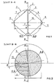
- An optoelectronic theodolite sensor is shown in the figures, the basic structure of which consists of a housing (2), a measuring cell (3), each containing two immiscible liquids (4, 5) that are overlayed, one of which is opaque (4 ) and the other is translucent (5), the dome or conical covers (6, 7), a light source (8) and a directly opposite optoelectronic component (9).
- the side surfaces A and B of the measuring cell are opaque, but the side surfaces C and D are translucent.
- the normal position of the optoelectronic theodolite sensor (1) is such that the interface (10) of the two immiscible liquids (4, 5) is exactly in the middle of the cylindrical measuring cell, which is achieved by filling the two liquids (4, 5) is achieved.
- the one liquid (4) must be colored opaque. This can be done by dye, depending on the type of the two liquids, by adding indicators, soot or other pigments. Above all, it must be ensured that the coloring remains selectively and extremely stable over the years. In order to prevent sedimentation of the pigment, the particle size must be selected so fine that BROWN's molecular movement can work.
- the measuring cell (3) is preferably of cylindrical design in order to ensure a very simple function of the luminous flux (translucent surface) relative to the angle to achieve; namely proportionality.
- the ratio of the circular diameter E to the height F can be 10,000: 1 to 10: 1, preferably 2,000: 1 to 50: 1.
- the covers (6, 7) can be dome-shaped and / or conical and must be coated on the inside or coated with metal so that they have a high degree of reflection and thus ensure a uniform light distribution.
- the inner surfaces should preferably be coated with pure, white paint with a high degree of reflection.
- Suitable light sources (8) are light bulbs or light-emitting diodes which are matched to the optoelectronic component (9) with regard to wavelength and radiation power. Above all, care should be taken with the incandescent lamps that they are designed for stable and therefore calibratable photometric data through construction and artificial aging. In order to achieve a regular light distribution, it is appropriate to attach a flat, diffuse surface (11) in front of the light source (8).
- any optoelectronic receiver is suitable as an optoelectronic component (9), be it a photo resistor, photodiode, photo element, photo transistor, photo thyristor or a photo multiplier.
- the optoelectronic component (9) maintains a high linearity between the measured variable (voltage, resistance, current) and illuminance over several decades. Due to their proportionality between photocurrent resp. Short-circuit current and illuminance are suitable photodiodes, respectively. Excellent photo elements because there is no need for complex linearization.
- the distance R between the light source (8) and the optoelectronic component (9) must be selected and coordinated in such a way that, taking into account the extent of the transmitter (8) and receiver (9), a minimal error arises.
Landscapes
- Physics & Mathematics (AREA)
- Engineering & Computer Science (AREA)
- General Physics & Mathematics (AREA)
- Radar, Positioning & Navigation (AREA)
- Remote Sensing (AREA)
- Length Measuring Devices By Optical Means (AREA)
- Investigating Or Analysing Materials By Optical Means (AREA)
- Photometry And Measurement Of Optical Pulse Characteristics (AREA)
Description
- Die Erfindung betrifft einen optoelektronischen Theodolitsensor zum Messen von Vertikal- und/oder Höhenwinkeln gemäss dem Oberbegriff des Patentanspruches 1.
- In Abweichung von der in der Praxis üblichen Art, zur Messung von Winkeln für Navigation und Geodäsie oder zum Prüfen der Lage senkrechter und waagrechter Teile oder zur Messung der Neigungen des Erdbodens, von Lotschwankungen und Gezeiten des Erdkörpers oder für die Messung der Seismizität, Theodolite mit elektro-optischer Kreisablesung, Röhrenoder Dosenlibellen oder Sextanten einzusetzen, sieht die Konstruktion der Erfindung einen optoelektronischen Theodolitsensor vor, der nach entsprechender Auslegung für all diese Messaufgaben eingesetzt werden kann.
- Die zur Messung des sichtbaren oder künstlichen Horizontes eingesetzten Libellen, Pendel, kreiselgestützen Marken, Quecksilberhorizonte oder Spiegelglasscheiben können nur mit Hilfe von Teilkreisen oder Gradbogen zur Messung der Horizontal- oder Vertikalabweichung herangezogen werden. Zudem sind diese Instrumente oder Sensoren entweder sehr aufwendig in der Herstellung oder ungenau und ermöglichen meist nur einen begrenzten Anwendungsbereich.
- Hier will die Erfindung Abhilfe schaffen. Die Erfindung, wie sie in den Ansprüchen gekennzeichnet ist, löst die Aufgabe, einen optoelektronischen Theodolitsensor vorzuschlagen, bei dem alle Winkel zwischen der Horizontalen und der Vertikalen sehr exakt und unter Ausschluss mechanischer oder optischer Ablesung ermittelt werden können.
- Die durch die Erfindung erreichten Vorteile sind im wesentlichen darin zu sehen, dass sehr schnell und exakt alle Winkel zwischen der Horizontalen und der Vertikalen absolut gemessen werden können. Zudem besticht die Erfindung durch ihren einfachen Aufbau und durch die Ausnützung sehr exakter physikalischer Grössen. Ausserdem ist das zugrunde gelegte Messprizip berührungslos und unempfindlich gegenüber äusseren Einflüssen.
- Durch Abstimmung und entsprechender Auslegung kann die Erfindung in praktisch allen Bereichen der Technik, in welchen exakte Winkel oder die Horizontale resp. die Vertikale sowie Winkelabweichungen derselben interessieren, Verwendung finden.
- Im folgenden wird die Erfindung anhand von lediglich einen Ausführungsweg darstellenden Zeichnungen näher erläutert.
- Es zeigt
- Figur 1 im Schnitt A-A einen optolektronischen Theodolitsensor,
- Figur 2 das Schnittbild B-B der Figur 1.
- In den Figuren ist ein optoelektronischer Theodolitsensor dargestellt, welcher in seinem grundsätzlichen Aufbau aus einem Gehäuse (2), einer Messzelle (3), die je zur Hälfte zwei nichtmischbare, überschichtet vorliegende Flüssigkeiten (4, 5) enthält, wobei die eine lichtundurchlässig (4) und die andere lichtdurchlässig (5) ist, den kalotten- oder kegelförmigen Abdeckungen (6, 7), einer Lichtquelle (8) und einem direkt gegenüberliegenden optoelektronischen Bauelement (9) besteht.
- Erfindungsgemäss sind die Seitenflächen A und B der Messzelle lichtundurchlässig, die Seitenflächen C und D jedoch lichtdurchlässig. Der optoelektronische Theodolitsensor (1) steht in seiner Normallage so, dass sich die Grenzfläche (10) der zwei nichtmischbaren Flüssigkeiten (4, 5) exakt in der Mitte der zylinderförmigen Messzelle befindet, was durch exaktes 1: 1 Auffüllen der zwei Flüssigkeiten (4, 5) erreicht wird.
- Wird nun die Normallage um einen positiven oder einen negativen Winkelgedreht, so verkleinert resp. vergrössert sich die scheinbare Fläche des in der Normallage exakten 1/4 Kreissektors der Seitenflächen C und D, da die lichtundurchlässige Flüssigkeit (4) nun einen grösseren resp. kleineren Kreissektor abdeckt. Diese Veränderung der scheinbaren Fläche reduziert resp. vergrössert den Lichtstrom auf das optoelektronische Bauelement (9), dessen Signaländerung nun in Funktion des Winkels
 umgeformt und als Messgrösse herangezogen wird.
- Eine besonders zweckmässige Gestaltung des optoelektronischen Theodolitsensors mit den kennzeichnenden Merkmalen des Hauptanspruchs sieht vor, dass die zwei nichtmischbaren Flüssigkeiten eine möglichst unterschiedliche Dichte aufweisen. Ausserdem sind vorzugweise Flüssigkeiten mit möglichst tiefem Dampfdruck resp. Schmelzpunkt einzufüllen. Hier eignen sich viele organische und auch anorganische Verbindungen, wie z.B. die folgenden Binärsysteme:
- Höhere ein- und mehrwertige Alkohole/aromatische Verbindungen oder halogenierte Kohlenwasserstoffe;
- organische Säureanhydride/aliphatische Kohlenwasserstoffe;
- Quecksilber, Wasser mit Tensid- oder Alkoholzusatz, Schwefelkohlenstoff/aliphatische oder aromatische Verbindungen und viele andere mehr.
- Sofern als lichtundurchlässige Flüssigkeit nicht Quecksilber eingefüllt wird, ist die eine Flüssigkeit (4) lichtundurchlässig einzufärben. Dies kann durch Farbstoff, je nach Art der beiden Flüssigkeiten auch durch Indikatorzusatz, Russ oder andere Pigmente geschehen. Vor allem ist darauf zu achten, dass die Einfärbung selektiv und äusserst stabil über Jahre unverändert bestehen bleibt. Um eine Sedimentation des Pigmentes zu verhindern, ist dessen partikelgrösse derart fein zu wählen, dass die BROWNsche Molekularbewegung wirken kann.
- Die Messzelle (3) ist mit Vorzug zylinderförmig auszubilden, um eine sehr einfache Funktion des Lichtstroms (durchscheinende Fläche) zum Winkelzu erzielen; nämlich Proportionalität.

- Das Verhältnis Kreisdurchmesser E zur Höhe F kann dabei 10′000: 1 bis 10: 1, vorzugsweise 2′000: 1 bis 50: 1 betragen. Die Abdeckungen (6, 7) können kalotten- und/oder kegelförmig ausgebildet sein und sind innen derart zu beschichten oder mit Metall zu bedampfen, dass sie einen hohen Reflexionsgrad aufweisen und somit eine gleichmässige Lichtverteilung gewährleisten. Vorzugsweise sind die Innenflächen mit reiner, weisser Farbe mit hohem Reflexionsgrad zu beschichten.
- Als Lichtquelle (8) eignen sich Glühlampen oder Leuchtdioden, die auf das optoelektronische Bauelement (9) hinsichtlich Wellenlänge und Strahlungsleistung abgestimmt sind. Vor allem ist bei den Glühlampen darauf zu achten, dass sie durch Konstruktion und künstliche Alterung auf stabile und damit kalibrierbare fotometrische Daten ausgelegt sind. Um eine regelmässige Lichtverteilung zu erzielen, ist es angebracht vor die Lichtquelle (8) eine ebene diffus strahlende Fläche (11) anzubringen. Als optoelektronisches Bauelement (9) eignet sich grundsätzlich jeder optoelektronische Empfänger, sei dies nun ein Fotowiderstand, Fotodiode, Fotoelement, Fototransistor, Fotothyristor oder ein Fotomultiplier. Vor allem ist darauf zu achten, dass das optoelektronische Bauelement (9) eine hohe Linearität zwischen Messgrösse (Spannung, Widerstand, Strom) und Beleuchtungsstärke über mehrere Dekaden beibehält. Aufgrund ihrer Proportinalität zwischen Fotostrom resp. Kurzschlussstrom und Beleuchtungsstärke eigenen sich Fotodioden resp. Fotoelemente vorzüglich, da eine aufwendige Linearisierung entfällt. Der Abstand R zwischen Lichtquelle (8) und optoelektronischem Bauelement (9) ist derart zu wählen und abzustimmen, dass unter Berücksichtigung der Ausdehnung von Sender (8) und Empfänger (9) ein minimaler Fehler entsteht.
Claims (4)
Priority Applications (1)
| Application Number | Priority Date | Filing Date | Title |
|---|---|---|---|
| AT87905582T ATE64003T1 (de) | 1986-09-15 | 1987-09-08 | Optoelektronischer theodolitsensor. |
Applications Claiming Priority (2)
| Application Number | Priority Date | Filing Date | Title |
|---|---|---|---|
| CH3686/86 | 1986-09-15 | ||
| CH3686/86A CH673890A5 (de) | 1986-09-15 | 1986-09-15 |
Publications (2)
| Publication Number | Publication Date |
|---|---|
| EP0281584A1 EP0281584A1 (de) | 1988-09-14 |
| EP0281584B1 true EP0281584B1 (de) | 1991-05-29 |
Family
ID=4261336
Family Applications (1)
| Application Number | Title | Priority Date | Filing Date |
|---|---|---|---|
| EP87905582A Expired - Lifetime EP0281584B1 (de) | 1986-09-15 | 1987-09-08 | Optoelektronischer theodolitsensor |
Country Status (6)
| Country | Link |
|---|---|
| US (1) | US4861981A (de) |
| EP (1) | EP0281584B1 (de) |
| JP (1) | JPH01500849A (de) |
| AU (1) | AU7870887A (de) |
| CH (1) | CH673890A5 (de) |
| WO (1) | WO1988002100A1 (de) |
Families Citing this family (6)
| Publication number | Priority date | Publication date | Assignee | Title |
|---|---|---|---|---|
| CA1314706C (en) * | 1988-08-02 | 1993-03-23 | Kikuo Shimura | Inclination angle detector |
| US5177872A (en) * | 1990-10-05 | 1993-01-12 | Texas Instruments Incorporated | Method and apparatus for monitoring physical positioning of a user |
| JP3072779B2 (ja) * | 1991-02-26 | 2000-08-07 | 株式会社トプコン | 傾斜角検出装置 |
| BE1005207A3 (nl) * | 1991-08-28 | 1993-05-25 | Smet Aqua Nv | Inrichting voor het meten van een helling en/of het detekteren of meten van een variatie van helling of snelheid. |
| US5704130A (en) * | 1992-01-22 | 1998-01-06 | Raytec Ag | Measuring instrument |
| WO2006023701A1 (en) * | 2004-08-19 | 2006-03-02 | Johnson Level & Tool Mfg. Co., Inc. | Indicator vial |
Family Cites Families (7)
| Publication number | Priority date | Publication date | Assignee | Title |
|---|---|---|---|---|
| US3487303A (en) * | 1967-01-24 | 1969-12-30 | Singer General Precision | Device for sensing deviation from the vertical position |
| US3863067A (en) * | 1972-07-24 | 1975-01-28 | Cornelius Leonard Gooley | Orientation indicating apparatus |
| US4154000A (en) * | 1976-01-12 | 1979-05-15 | The Brunton Company | Remote level sensing instrument |
| JPS56107113A (en) * | 1980-01-30 | 1981-08-25 | Furukawa Electric Co Ltd:The | Detecting method for tilt angle |
| US4307516A (en) * | 1980-02-07 | 1981-12-29 | The United States Of America As Represented By The Secretary Of The Army | Directional two-axis differential optical inclinometer |
| EP0117226A3 (de) * | 1983-01-28 | 1985-10-02 | Max Engler | Messinstrument zum Feststellen von Abweichungen bezüglich dem Lot und/oder der Waagrechten und Verwendung desselben |
| GB2152659B (en) * | 1984-01-12 | 1987-04-15 | Norman John Ivermee | Device for measuring direction of accleration and/or inclination |
-
1986
- 1986-09-15 CH CH3686/86A patent/CH673890A5/de not_active IP Right Cessation
-
1987
- 1987-09-08 EP EP87905582A patent/EP0281584B1/de not_active Expired - Lifetime
- 1987-09-08 AU AU78708/87A patent/AU7870887A/en not_active Abandoned
- 1987-09-08 WO PCT/CH1987/000113 patent/WO1988002100A1/de not_active Ceased
- 1987-09-08 JP JP62505105A patent/JPH01500849A/ja active Pending
-
1988
- 1988-05-10 US US07/192,192 patent/US4861981A/en not_active Expired - Fee Related
Also Published As
| Publication number | Publication date |
|---|---|
| AU7870887A (en) | 1988-04-07 |
| WO1988002100A1 (fr) | 1988-03-24 |
| EP0281584A1 (de) | 1988-09-14 |
| CH673890A5 (de) | 1990-04-12 |
| US4861981A (en) | 1989-08-29 |
| JPH01500849A (ja) | 1989-03-23 |
Similar Documents
| Publication | Publication Date | Title |
|---|---|---|
| DE112007000198B4 (de) | Mehrachsiger Blasen-Hohlkörper | |
| DE19941638C1 (de) | Geodätisches Gerät mit Laseranordnung | |
| DE2750933A1 (de) | Tacheometer | |
| DE3990869C2 (de) | Neigungswinkeldetektor | |
| DE3634244A1 (de) | Optoelektronischer neigungssensor | |
| WO2008064731A1 (de) | Neigungssensor mit optoelektronischer libelle | |
| DE2339948A1 (de) | Digitaler magnetkompass | |
| WO1988002100A1 (fr) | Detecteur optoelectronique pour theodolites | |
| CH673707A5 (de) | ||
| WO2003104748A1 (de) | Optischer neigungsmesser | |
| EP1076807B1 (de) | Optischer neigungsmesser | |
| DE3611559C2 (de) | Geodätisches Gerät | |
| DE4320494C1 (de) | Neigungssensor für ein Fahrzeug | |
| EP0626061B1 (de) | Messgerät | |
| EP2553388B1 (de) | Optoelektronischer neigungssensor | |
| DE4013507C2 (de) | Behälter mit Flüssigkeit | |
| EP2823263B1 (de) | Optoelektronische lagemessvorrichtung | |
| CN87210507U (zh) | 圆弧形水准器 | |
| DD295413A5 (de) | Neigungssensor | |
| RU2080562C1 (ru) | Уровнемер для жидкости | |
| DE4129861A1 (de) | Libelle | |
| DE2804639A1 (de) | Fuellstandsanzeiger | |
| EP2183650A2 (de) | Rotationssymmetrische brechungssonnenuhr | |
| DE2324259C3 (de) | Einrichtung zum Messen der Dichte einer Flüssigkeit unter Ausnutzung des Brechungsgesetze s | |
| DE10135329B4 (de) | Vorrichtung zur Messung von Neigungswinkeln |
Legal Events
| Date | Code | Title | Description |
|---|---|---|---|
| PUAI | Public reference made under article 153(3) epc to a published international application that has entered the european phase |
Free format text: ORIGINAL CODE: 0009012 |
|
| 17P | Request for examination filed |
Effective date: 19880511 |
|
| AK | Designated contracting states |
Kind code of ref document: A1 Designated state(s): AT BE CH DE FR GB IT LI LU NL SE |
|
| 17Q | First examination report despatched |
Effective date: 19900223 |
|
| GRAA | (expected) grant |
Free format text: ORIGINAL CODE: 0009210 |
|
| AK | Designated contracting states |
Kind code of ref document: B1 Designated state(s): AT BE CH DE FR GB IT LI LU NL SE |
|
| PG25 | Lapsed in a contracting state [announced via postgrant information from national office to epo] |
Ref country code: IT Free format text: LAPSE BECAUSE OF FAILURE TO SUBMIT A TRANSLATION OF THE DESCRIPTION OR TO PAY THE FEE WITHIN THE PRESCRIBED TIME-LIMIT;WARNING: LAPSES OF ITALIAN PATENTS WITH EFFECTIVE DATE BEFORE 2007 MAY HAVE OCCURRED AT ANY TIME BEFORE 2007. THE CORRECT EFFECTIVE DATE MAY BE DIFFERENT FROM THE ONE RECORDED. Effective date: 19910529 Ref country code: SE Effective date: 19910529 Ref country code: NL Effective date: 19910529 Ref country code: BE Effective date: 19910529 Ref country code: GB Effective date: 19910529 Ref country code: FR Effective date: 19910529 |
|
| REF | Corresponds to: |
Ref document number: 64003 Country of ref document: AT Date of ref document: 19910615 Kind code of ref document: T |
|
| REF | Corresponds to: |
Ref document number: 3770453 Country of ref document: DE Date of ref document: 19910704 |
|
| PG25 | Lapsed in a contracting state [announced via postgrant information from national office to epo] |
Ref country code: AT Effective date: 19910908 |
|
| PG25 | Lapsed in a contracting state [announced via postgrant information from national office to epo] |
Ref country code: LU Free format text: LAPSE BECAUSE OF NON-PAYMENT OF DUE FEES Effective date: 19910930 |
|
| EN | Fr: translation not filed | ||
| NLV1 | Nl: lapsed or annulled due to failure to fulfill the requirements of art. 29p and 29m of the patents act | ||
| GBV | Gb: ep patent (uk) treated as always having been void in accordance with gb section 77(7)/1977 [no translation filed] | ||
| PGFP | Annual fee paid to national office [announced via postgrant information from national office to epo] |
Ref country code: CH Payment date: 19911231 Year of fee payment: 5 |
|
| PLBE | No opposition filed within time limit |
Free format text: ORIGINAL CODE: 0009261 |
|
| STAA | Information on the status of an ep patent application or granted ep patent |
Free format text: STATUS: NO OPPOSITION FILED WITHIN TIME LIMIT |
|
| 26N | No opposition filed | ||
| PG25 | Lapsed in a contracting state [announced via postgrant information from national office to epo] |
Ref country code: DE Effective date: 19920602 |
|
| PG25 | Lapsed in a contracting state [announced via postgrant information from national office to epo] |
Ref country code: LI Effective date: 19920930 Ref country code: CH Effective date: 19920930 |
|
| REG | Reference to a national code |
Ref country code: CH Ref legal event code: PL |