EP0281369B1 - Flügelzellenmotor mit verstellbarer Durchflussmenge - Google Patents
Flügelzellenmotor mit verstellbarer Durchflussmenge Download PDFInfo
- Publication number
- EP0281369B1 EP0281369B1 EP88301796A EP88301796A EP0281369B1 EP 0281369 B1 EP0281369 B1 EP 0281369B1 EP 88301796 A EP88301796 A EP 88301796A EP 88301796 A EP88301796 A EP 88301796A EP 0281369 B1 EP0281369 B1 EP 0281369B1
- Authority
- EP
- European Patent Office
- Prior art keywords
- bore
- shaft
- piston
- vanes
- pressure
- Prior art date
- Legal status (The legal status is an assumption and is not a legal conclusion. Google has not performed a legal analysis and makes no representation as to the accuracy of the status listed.)
- Expired - Lifetime
Links
- 238000006073 displacement reaction Methods 0.000 title claims abstract description 24
- 239000007788 liquid Substances 0.000 claims description 23
- 239000012530 fluid Substances 0.000 claims description 16
- 238000007789 sealing Methods 0.000 claims description 2
- 238000007599 discharging Methods 0.000 claims 1
- 230000007659 motor function Effects 0.000 claims 1
- 230000005540 biological transmission Effects 0.000 description 6
- 230000006870 function Effects 0.000 description 3
- 238000002485 combustion reaction Methods 0.000 description 2
- 230000001276 controlling effect Effects 0.000 description 2
- 230000003247 decreasing effect Effects 0.000 description 2
- 238000010586 diagram Methods 0.000 description 2
- 241001379910 Ephemera danica Species 0.000 description 1
- 230000033228 biological regulation Effects 0.000 description 1
- 238000010276 construction Methods 0.000 description 1
- 230000008878 coupling Effects 0.000 description 1
- 238000010168 coupling process Methods 0.000 description 1
- 238000005859 coupling reaction Methods 0.000 description 1
- 230000000694 effects Effects 0.000 description 1
- 239000000446 fuel Substances 0.000 description 1
- 210000004907 gland Anatomy 0.000 description 1
- 230000007935 neutral effect Effects 0.000 description 1
- 238000012856 packing Methods 0.000 description 1
- 230000001105 regulatory effect Effects 0.000 description 1
- 230000000717 retained effect Effects 0.000 description 1
- 238000005096 rolling process Methods 0.000 description 1
Images

Classifications
-
- F—MECHANICAL ENGINEERING; LIGHTING; HEATING; WEAPONS; BLASTING
- F04—POSITIVE - DISPLACEMENT MACHINES FOR LIQUIDS; PUMPS FOR LIQUIDS OR ELASTIC FLUIDS
- F04C—ROTARY-PISTON, OR OSCILLATING-PISTON, POSITIVE-DISPLACEMENT MACHINES FOR LIQUIDS; ROTARY-PISTON, OR OSCILLATING-PISTON, POSITIVE-DISPLACEMENT PUMPS
- F04C14/00—Control of, monitoring of, or safety arrangements for, machines, pumps or pumping installations
- F04C14/18—Control of, monitoring of, or safety arrangements for, machines, pumps or pumping installations characterised by varying the volume of the working chamber
- F04C14/185—Control of, monitoring of, or safety arrangements for, machines, pumps or pumping installations characterised by varying the volume of the working chamber by varying the useful pumping length of the cooperating members in the axial direction
Definitions
- the present invention is directed to a vane type variable displacement motor having a cylindrical body with means for modifying the internal volume and corresponding speed of rotation of a drive shaft driven by a source of pressurized liquid.
- An object of the present invention is to provide a vane type variable displacement motor whose speed can be changed by varying the size and volume of the chamber within which the rotor and vanes turn.
- the present invention provides a van type variable displacement motor comprising a cylindrical body having an elliptical first bore, centrally apertured end caps secured to said body sealing said bore and including an internal axial bore communicating with said first bore, a drive shaft axially extending through said body and end caps and journaled and sealed upon said end caps, a cylindrical rotor upon said shaft spaced from said first bore and having a series of slots around its periphery, a plurality of elongated vanes slidably mounted in said slots and adapted to engage said first bore.
- an intake passage in said body for directing pressurized liquid to said first bore and vanes from a pressure source, and an outlet passage for receiving exhaust liquid from said first bore
- a rotatable piston mounted on said shaft within one end cap bore and having a series of slots therein for cooperatively receiving said vanes, whereby said piston is adapted for axial movements within said end cap and into said first bore and relative to said vanes for modifying the effective internal volume of said first bore and the speed of rotation of said shaft, the pressure of liquid flowing through said body normally biasing said piston outwardly, a pilot port in the end cap communicating with said axial bore adjacent said piston, and variable pressure means connected to said pilot port for biasing said piston inwardly of said end cap and variably into said first bore.
- An embodiment of the invention is to provide within said body at its opposite ends within said end caps respectively a pair of rotatable pistons mounted upon said shaft, each piston having a series of radial slots cooperatively receiving the vanes whereby the respective pistons are adapted for axial movements into the elliptical bore and relative to the vanes for modifying the effective internal volume of the body and the speed of rotation of the shaft, assuming that there is a steady supply of pressurized fluid, such as oil, delivered to the motor from a suitable pump.
- pressurized fluid such as oil
- Another embodiment is to provide within the end caps pilot ports connectable to a variable pressure source by which pressure applied to the outer end of the respective pistons overcomes the internal pressure of the pressure fluids passing through the motor body such as will effect inward movement of the respective pistons into the elliptical bore whereby the volume of fluid displaced per revolution is reduced so that with a uniform supply of pressurized liquid coming into the motor the speed of the shaft will increase.
- Said embodiment may include means by which the reduction of pressure applied to the respective pistons permits the pistons to move outwardly relative to the vanes so as to increase the internal volume of fluid displaced so that with a uniform supply of pressurized liquid coming into the motor the speed of the shaft will be reduced.
- Said slots in said rotor may be radial or non-radial angular slots within which said vanes may be yieldably positioned for movement generally radially of the shaft to contact said bore.
- the pressure source for the present motor may be a pump driven from an external power source which could be from the motor of an internal combustion engine, for illustration, and wherein the pump has an outlet for delivery to the intake passage of the motor body for application to the respective vanes upon the rotor and shaft and for exhausting through a corresponding exhaust passage in said body for return to a sump in turn connected to the intake of said pump by which pressurized liquid, such as oil, is delivered at a uniform pressure and quantity to and through the body of the motor for application to the vanes and for driving the rotor at a predetermined speed.
- pressurized liquid such as oil
- Adjustable control valves may be interposed into the conduits to said pilot ports for selectively modifying the pressure of liquid delivered to the respective pistons which is sufficient to overcome the internal liquid pressure of said motor, which causes inward positioning of the respective pistons into the elliptical bore, in turn reducing the total effective volume and displacement of liquids within the motor and increasing the speed of rotation of the driven shaft.
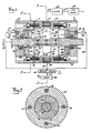
- the present vane type variable displacement motor 11 is shown in Figures 1, 2 and 3, and includes a cylindrical body 13 having an elliptically shaped bore 14 and at its opposite ends apertured end caps 15 secured thereto by fasteners 16. Each of the end caps includes a radial face 17 engaging the corresponding end face of body 13 and sealed thereto at 31.
- Spaced ball bearings 18 are nested and retained within end caps 15 on the interior thereof and are adapted to cooperatively receive, support and journal elongated drive shaft 19, fragmentarily shown.
- the drive shaft 19 is adapted to do work of any nature as for example it may be a part of a continuously variable transmission, (CVT) for a vehicle, for illustration, though not limited thereto. Any other bearings such as roller bearings or needle bearings may be used.
- drive shaft 19 Intermediate the ends of drive shaft 19 are a pair of increased diameter end thrust shoulders 20 upon the interior of end caps 15 and in registry with ball bearings 18. Said shoulders are adapted to restrain shaft 19 against endwise movement relative to said body and end caps.
- Rotor 21 is part of drive shaft 19 intermediate its ends and is spaced from bore 14 and from end caps 15.
- a series of radial slots 22, Figure 3 are formed longitudinally through said rotor and are adapted to receive the corresponding radial vanes 23, of rectangular shape which extend therethrough. Said vanes are normally spaced from central cut away portions 25 in the shaft 19 and extend radially outward for engagement with elliptical bore 14. The respective vanes are normally biased radially outward by a plurality of springs 26 nested in recesses 27.
- Each piston has formed therethrough upon its inner side a series of radial slots 30 which correspond to radial slots 22 in rotor 21.
- Corresponding ends of vanes 23 are slidably received within piston slots 30, Figure 1, whereby the corresponding pistons are adapted for axial adjustments inwardly and outwardingly with respect to chamber 14 as designated by the arrows in Figure 1.
- the respective pistons 29 are sealed within bore 28 and with respect to shaft 19 by corresponding additional seals 31, and said shaft is further sealed with respect to end caps 15 by packing glands 33.
- Intake passage 35 Upon one side of body 13 intermediate its ends, is an elongated intake passage 35 communicating with bore 14. Arranged upon the opposite side of said body is an exhaust outlet passage 37. Intake passage 35 is adapted for connection to a suitable pressure source such as hydraulic pump 39, schematically shown in Figure 1, having an outlet 41 which is suitably connected by proper fittings to said intake passage.
- a suitable pressure source such as hydraulic pump 39, schematically shown in Figure 1, having an outlet 41 which is suitably connected by proper fittings to said intake passage.
- the corresponding exhaust passage 37 is connected by conduit 43 to a sump 45, schematically shown, which through an additional conduit 47 is further connected to pump 39, provided for recirculation of the driving liquid, as for example oil under pressure.
- Pump 39 operates at a uniform pressure and delivers a uniform volume of liquid to intake passage 35 in figure 3 for direction upon vanes 23 and clockwise through exhaust passage 37 to said sump.
- the pistons 29 Normally the internal fluid pressure biases the pistons 29 outwardly such as to the position shown and wherein their annular abutment flanges 55 are in cooperative engaging registry with end caps 15.
- an additional intake passage 35 and exhaust passage 37 are similarly connected to pump 39 and sump 45.
- the respective pistons are adapted for inward movements along shaft 19 and into elliptical bore 14 of body 13.
- valve 51 is a manually operated pressure control valve. It can actually reduce line pressure by draining it through a conduit back to sump 45.
- line pressure is meant the pressure that is available in conduit 53, which is determined by the resistance or load applied to shaft 19.
- Line pressure can be anywhere from 0 to 500 PSI, (0 - 3,5 MPa) depending on the resistance that shaft 19 encounters. If valve 51 is set at zero pressure, the piston 29 will be forced against end cap 15 by the pressure of fluid passing through bore 14 during normal operation of motor 11. If there is a need or desire to increase the speed of rotation of shaft 19, valve 51 is manually adjusted to increase the pressure against piston 29 until it overcomes the internal pressure and biases piston 29 toward rotor 21, resulting in an increase in speed.
- valve 51 can be adjusted so that the force against both sides of piston 29 is equal and the speed will remain constant.
- the speed of motor shaft 19 can then be reduced by manually adjusting the pressure of valve 51, so that the force in bore 14 biases piston 27 away from the rotor 21, resulting in a decrease in speed of rotation of shaft 19.
- Valve 51 is a manually operated control valve that acts in responset to the operator's need to adjust the speed of rotation of motor shaft 19.
- an elongated annular groove 57 which communicates with the respective intake passage 35, exhaust passage 37 and the corresponding vanes 23 along their length for increased responsiveneness to the fluids directed into and through said motor body.
- vanes 23 are shown as radial vanes, it is contemplated that instead of radial, the vanes could be nested within angular slots.
- the present output shaft 19 for the vane type variable displacement motor would be particularly adaptable as a part of a CVT for a vehicle such as in the automotive industry, though not limited thereto.
- vanes While six vanes are shown in Figure 3, it is contemplated that the number of vanes could be increased or decreased. While the vanes are uniformly spaced, they could be variably spaced.
- the pressure control valves 51, Figure 1 can be set to increase or decrease pressure to be applied to the respective pistons 29, within motor bore 14. If the pistons move inwardly the speed of rotation of shaft 19 increases. If the pistons move outward from an inner position, the speed of rotation of shaft 19 is decreased due to the increased internal volume of elliptical bore 14.
- the pump has a capacity of 5 gallons per minute (19 dm3/min) at 1000 RPM, and recommended operating pressure not to exceed 500 pounds per square inch 3,5 MPa.
- pump 39 may be driven by an internal combustion engine on a vehicle and the shaft 19 could be a part of a continuously variable transmission.
- a pressure relief valve 61 is connected into pump outlet pipe 41 for limiting the pressure of pressurized hydraulic fluids in this system, Figure 1. Valve 61 will respond to an overload of the motor, by exhausting excess pressure.
- body 13 has a pair of diametrically opposed intake passages 35 and opposed exhaust passages 37. This provides for an improved balance of pressure upon rotor 21, Figure 1, from opposite sides of the motor.
- FIG. 4 A modified hydraulic diagram is shown in Figure 4 wherein a directional control valve 63 is connected to pump 39 and exhaust sump 45.
- Remote controlled solenoids 1 and 2 control the movable valve element in the valve so that pressurized liquid delivered to intake passage 35 may be reversed for delivery to the exhaust passage 37.
- Rotor 21 and shaft 19 will rotate in the opposite direction. Exhaust liquid from passage 35 returns to said sump.
- pressurized fluid from the outlet would be channelled back through pressure control valves 51 to the pilot ports 49 at the ends of the pump to bias the rotative pistons 29 inward.
- pressure control valves 51 By adjusting the pressure control valves 51, the displacement of the pump can be changed.
- the present vane type variable displacement motor could be used as an integral part of a continuously variable transmission (CVT). It would thus be possible to build a CVT using a pair of vane type variable displacement motor/pumps; one acting as a pump and the other acting as a motor.
- CVT continuously variable transmission
- Vane end play is prevented by the reduced diameter piston chambers 28, Figure 1.
- the vanes are variably biased outwardly by the springs 26 and centrifugal forces towards engagement with elliptical bore 14, Figure 3.
- the hydraulic circuit in Figure 1 and Figure 4 is illustrative of two embodiments of the present invention, and can be modified to meet changing conditions. While six vanes 23 are shown, two or more may be employed.
- chamber 14 is shown as elliptical in form it could be of a different form as out of round.
- the present motor 11, or pump preferably shows a pair of rotative pistons 29. It could function with only one such piston.
- the present motor could have three inlets and three opposed outlets.
- Conduits 53 in Figure 4 interconnect pump outlet 41 and the respective pilot ports 49 on motor 11, as shown in Figure 1.
- Pressure control valves 51 are interposed in conduits 53 and drain into sump 45.
- Adjustable pressure relief valve 61 is connected into pump outlet pipe 41 and drains into sump 45.
- Solenoid controlled valves 67 are interposed respectively in pipe 41 to motor inlet 35 and in pipe 43 connected to outlet 37. Pressure gauges are shown at 65 in pipes 53, 43 and 41.
- Valve 61 can be manually set to exhaust pressure that exceeds 500 PSI (3,5 MPa).
- the output of the pump would be connected by conduit 41 to valve 63, which can be controlled by the gear shift lever of that vehicle.
- valve 63 which can be controlled by the gear shift lever of that vehicle.
- ECM electronice control module 69
- the ECM would also monitor and control engine speed, and also monitor road speed and throttle position.
- Valves 51, and valves 67 are actually modulated digital signal (MDS) solenoids whose function is different because of their being piped differently.
- MDS solenoid is a solenoid whose shaft blocks a passageway when it is in the "on” position. This solenoid can be cycled “on” 100 times a second, for illustrative purposes, and the duration of each "on" cycle can be controlled. By controlling the time or width of each cycle, the amount that the passageway is blocked can be controlled in finite increments.
- gauges 65 (electrical connections now shown), which are pressure transducers that will transmit to the ECM 69 what the instantaneous pressure is in each of those four places.
- the MDS solenoid, valves 51 block the path for the oil to pass to the sump, when the valve is in the on position. In this way valve 51 controls the pressure that biases the pistons toward the rotor.
- the MDS solenoid valve 67 will block the rate of flow of fluid in conduit 41 and 43, when it is in the on position.
- the ECM 69 will know what the pressure is at the end caps 15, and in two places of chamber 14.
- the ECM will know the engine speed, the road speed, the throttle position, and the gear shift position.
- the ECM will be able to control valves 51, valves 67, and the engine speed. All the aforementioned devices are hooked up to the ECM electrically (not shown in Figure 4).
- the ECM schematically shown at block 69, Figure 4, will have memory space that can be programmed with different parameters for the operation of the vehicle. For instance, these software parameters can be changed so that the vehicle could accelerate swiftly or gradually.
- the proposed ECM would control a vehicle.
- the driver would start the engine, which would idle at 1000 RPM.
- the driver would then move the gear shift lever 71 to drive, and the ECM would send a signal to valve 63 to shift to position one. This would cause 5 gallons per minute to pass into inlet 35. Pressure would increase in bore 14 until it overcame the resistance of shaft 19 to turn.
- the vehicle would begin to move.
- the driver would press on the throttle which would increase engine RPM, causing more gallons per minute to go through motor 19, in turn increasing vehicle speed.
- valve 51 which would have been pulsing valve 51 to keep the pressure against port 49 lower than the pressure in bore 14, would now pulse valve 51 to the 100% "on" condition so that the drain would be blocked, increasing pressure to port 49, biasing piston 29 inward, and increasing vehicle speed.
- the ECM could cause one or both pistons 29 to move inward, to increase speed gradually or swiftly.
- valve 51 When the desired road speed is reached, as determined by the ECM from the throttle position input, valve 51 would be pulsed at less than 100% so that the piston 29 would remain in a fixed axial position and vehicle speed would remain constant.
- valve 51 If the vehicle were to go down a hill, a decrease in pressure in bore 14 would be detected, and the ECM could pulse valve 51 so that pressure at port 49 is reduced proportionally and speed would remain constant. If the incline that the vehicle is going down is steep, valve 67 that is on the outlet 37 side, could be pulsed so that the flow of oil is reduced which would "brake” the motor 19. The oil that is not permitted past valve 67 would be exhausted at relief valve 61.
- the ECM would detect an increase in pressure in bore 14.
- the ECM would adjust engine speed and valve 51 proportionally, so that vehicle speed would remain constant.
- the pressure in the system is determined by the load that shaft 19 must push.
- On level ground that load is constant and the ECM would maintain a constant engine speed.
- the ECM could be programmed to operate in a fuel efficient manner or a sporty manner.
- the ECM could be programmed for different vehicle size and weight, and different engine size. If a smooth shift is desired from neutral to drive, valve 67 on the inlet 35 side could be pulsed in a manner that would gradually feed the oil to bore 14.
- the ECM When the desired road speed has been reached, the ECM would reduce motor 11 volume to the minimum while reducing engine speed (hence reducing (delivery capacity) gallons/minute), so that minimal energy output would be used to keep the vehicle rolling.
- Valve 67 on the inlet 35 side of motor 11 could be used to accelerate motor 11 rapidly by momentarily interrupting the flow of oil to the motor 11, which would assist the inward movement of pistons 29.
- the proposed control system as shown hydraulically in Figure 4 is an alternative to the manual system of Figure 1.
Landscapes
- Engineering & Computer Science (AREA)
- Mechanical Engineering (AREA)
- General Engineering & Computer Science (AREA)
- Hydraulic Motors (AREA)
- Supercharger (AREA)
- Percussion Or Vibration Massage (AREA)
- External Artificial Organs (AREA)
Claims (7)
- Flügelzellenmotor (11) mit variablem Volumen, gekennzeichnet durch einen zylindrischen Körper (13) mit einer elliptischen ersten Bohrung (14),
mit Zentralbohrung versehene Stirnkappen (15), die am Körper (13) zum Verschließen der Bohrung (14) befestigt sind und eine mit der ersten Bohrung (14) kommunizierende innere Axialbohrung (28) aufweisen,
eine den Körper (13) und die Stirnkappen (15) axial durchsetzende und in den Stirnkappen (15) gelagerte und abgedichtete Antriebswelle (19),
einen auf der Welle (19) mit einem Abstand von der ersten Bohrung (14) sitzenden zylindrischen Rotor (21) mit einer Reihe von Schlitzen (22) um seinen Umfang herum,
eine Anzahl von länglichen Flügeln (23), die in den Schlitzen (22) für Radialverschiebung verschiebbar geführt sind und sich an die erste Bohrung (14) anzulegen vermögen,
einen im Körper (13) vorgesehenen Einlaßkanal (35) zum Einleiten von Druckflüssigkeit zur (in die) erste(n) Bohrung (14) und zu den Flügeln (23) von einer Druckquelle (39) her nebst einem Auslaßkanal (37) zum Aufnehmen bzw. Abführen von Ausstoßflüssigkeit aus der ersten Bohrung (14),
einen auf der Welle (19) innerhalb der einen Stirnkappenbohrung (28) montierten drehbaren Kolben (29) mit einer Reihe von darin ausgebildeten Schlitzen (30) zum gemeinsamen Aufnehmen der Flügel (23), wobei der Kolben (29) in der Stirnkappe (15) Axialverschiebungen relativ zum Rotor und in die erste Bohrung (14) und relativ zu den Flügeln (23) durchzuführen vermag, um das effektive Innenvolumen der ersten Bohrung (14) und die Drehzahl der Welle (19) zu modifizieren,
wobei der Druck der durch den Körper (13) strömenden Flüssigkeit den Kolben (29) normalerweise nach außen drängt,
einen in der Stirnkappe (15) vorgesehenen Steuerzulaß (49), der im Bereich des Kolbens (29) mit der Axialbohrung (28) kommuniziert,
und eine mit dem Steuerzulaß (49) verbundene variable Druckeinrichtung (39, 41, 51, 53) zum Vorbelasten des Kolbens (29) in Einwärtsrichtung der Stirnkappe (15) und variabel in die erste Bohrung (14) (hinein). - Motor mit variablem Volumen nach Anspruch 1, umfassend einen zweiten, innerhalb der anderen Stirnkappenbohrung (28) auf der Welle (19) sitzenden drehbaren Kolben (29) mit einer Reihe von in ihm ausgebildeten Schlitzen (30) zum gemeinsamen Aufnehmen der Flügel (23), wobei der zweite Kolben (29) Axialverschiebungen in der anderen Stirnkappenbohrung (28) und in die erste Bohrung (14) sowie relativ zu den Flügeln (23) durchzuführen vermag,
wobei der Druck der durch die erste Bohrung (14) strömenden Flüssigkeit den zweiten Kolben (29) normalerweise nach außen drängt, (und)
einen in der anderen Stirnkappe (15) vorgesehenen zweiten Steuerzulaß (49), der mit der Axialbohrung (28) im Bereich des zweiten Kolbens (29) kommuniziert,
wobei die variable Druckeinrichtung (39, 41, 51, 53) an den zweiten Steuerzulaß (49) angeschlossen ist, um den zweiten Kolben (29) in Einwärtsrichtung der zweiten Stirnkappe (15) und variabel in die erste Bohrung (14) (hinein) vorzubelasten. - Motor mit variablem Volumen nach Anspruch 1 oder 2, bei dem die Schlitze (22) im Rotor (21) radiale Schlitze sind und die Flügel (23) in den Schlitzen (22) für Radialverschiebung geführt sind.
- Motor mit variablem Volumen nach Anspruch 1, 2 oder 3, bei dem die variable Druckeinrichtung umfaßt:
eine die Druckquelle (39) und den Steuerzulaß (51) verbindende Leitung (53) und
ein einstellbares variables Druckregelventil (51) in der Leitung (53) zum Vorbelasten des Kolbens (29) in Einwärtsrichtung der Stirnkappe (15) und variabel in die erste Bohrung (14) (hinein), und
bei dem durch Modifizieren des Innenvolumens der ersten Bohrung (14) die maximalen Drehmomentleistungen des Motors aufrechterhaltbar sind. - Motor mit variablem Volumen nach einem der Ansprüche 1 bis 4, in Kombination mit einer Pumpe (39) zum Zuspeisen von Druckflüssigkeit zum Motor und einem an den Auslaß der Pumpe (39) angeschlossenen Druckminderventil (61) zum Variieren des Höchstdrucks der Flüssigkeit zum Motor.
- Motor mit variablem Volumen nach einem der vorangehenden Ansprüche, in Kombination mit einer Pumpe (39) und einem zwischen den Pumpenauslaß und die Motor-Einlaß-und -Auslaßkanäle (35, 37) eingeschalteten fernsteuerbaren Vierwegeventil (63), so daß die Strömung der Druckflüssigkeit durch den Motor zur Umkehrung der Drehung der Welle (19) zwischen Einlaß- und Auslaßkanälen (35, 37) umkehrbar bzw. umsteuerbar ist.
- Motor mit variablem Volumen nach einem der vorangehenden Ansprüche, in Kombination mit einer mit der Welle (19) verbundenen Antriebsmaschine zum Drehen der Welle, so daß der Motor als Pumpe zum Ansaugen von Flüssigkeit an seinem Auslaßkanal (37) und Austragen von Druckflüssigkeit an seinem Einlaßkanal (35) wirkt.
Priority Applications (1)
| Application Number | Priority Date | Filing Date | Title |
|---|---|---|---|
| AT88301796T ATE78323T1 (de) | 1987-03-04 | 1988-03-01 | Fluegelzellenmotor mit verstellbarer durchflussmenge. |
Applications Claiming Priority (2)
| Application Number | Priority Date | Filing Date | Title |
|---|---|---|---|
| US21785 | 1987-03-04 | ||
| US07/021,785 US4758137A (en) | 1987-03-04 | 1987-03-04 | Vane type variable displacement motor |
Publications (3)
| Publication Number | Publication Date |
|---|---|
| EP0281369A2 EP0281369A2 (de) | 1988-09-07 |
| EP0281369A3 EP0281369A3 (en) | 1989-04-12 |
| EP0281369B1 true EP0281369B1 (de) | 1992-07-15 |
Family
ID=21806131
Family Applications (1)
| Application Number | Title | Priority Date | Filing Date |
|---|---|---|---|
| EP88301796A Expired - Lifetime EP0281369B1 (de) | 1987-03-04 | 1988-03-01 | Flügelzellenmotor mit verstellbarer Durchflussmenge |
Country Status (4)
| Country | Link |
|---|---|
| US (1) | US4758137A (de) |
| EP (1) | EP0281369B1 (de) |
| AT (1) | ATE78323T1 (de) |
| DE (1) | DE3872731D1 (de) |
Families Citing this family (7)
| Publication number | Priority date | Publication date | Assignee | Title |
|---|---|---|---|---|
| US5660537A (en) * | 1995-09-05 | 1997-08-26 | Ford Motor Company | Self-regulating fuel supply pump |
| US5664941A (en) * | 1995-12-22 | 1997-09-09 | Zexel Usa Corporation | Bearings for a rotary vane compressor |
| US5738065A (en) * | 1996-08-30 | 1998-04-14 | Linnel; Jean | Variable rotary engine |
| US20110303184A1 (en) * | 2010-06-11 | 2011-12-15 | Usher Meyman | Internal combustion engine |
| CN102996438A (zh) * | 2012-12-20 | 2013-03-27 | 王荣花 | 潜油球塞泵 |
| US10113427B1 (en) | 2014-04-02 | 2018-10-30 | Brian Davis | Vane heat engine |
| JP7720316B2 (ja) * | 2020-03-20 | 2025-08-07 | 金徳創新技術股▲分▼有限公司 | 吸排量可変ポンプと、前記ポンプによって構成される駆動装置およびその駆動方法 |
Family Cites Families (20)
| Publication number | Priority date | Publication date | Assignee | Title |
|---|---|---|---|---|
| FR415786A (fr) * | 1909-05-14 | 1910-10-04 | Int Rotations Maschinen Ges M | Machine rotative à volume débité variable |
| US1603437A (en) * | 1921-02-08 | 1926-10-19 | Wingquist Sven Gustaf | Adjustable-capacity vane pump for hydraulic change-speed gears and other uses |
| US1527685A (en) * | 1922-04-03 | 1925-02-24 | Huwiler Anton | Rotary motor or pump for hydraulic gears |
| US1914090A (en) * | 1930-06-10 | 1933-06-13 | Hamilla George John | Hydraulic power transmission |
| US2307851A (en) * | 1939-06-01 | 1943-01-12 | George N Musick | Hydraulic device for variable speed transmissions |
| US2371922A (en) * | 1940-04-05 | 1945-03-20 | Saito Kiitiro | Variable speed hydraulic coupling |
| US2448108A (en) * | 1946-06-04 | 1948-08-31 | Jonathan H Mccaleb | Variable capacity rotary pump |
| US2775946A (en) * | 1953-03-02 | 1957-01-01 | George H Hufferd | Constant delivery variable pressure pump |
| US2925785A (en) * | 1955-01-27 | 1960-02-23 | Sander Erich | Hydraulic transmission |
| GB792944A (en) * | 1956-06-20 | 1958-04-09 | Hans Einarson Gjelsteen | Improvements in or relating to rotary pumps or motors of the sliding vane type with infinitely variable internal displacement |
| US3250223A (en) * | 1962-05-14 | 1966-05-10 | Trojan Corp | Vane impulsion apparatus |
| US3740954A (en) * | 1972-03-20 | 1973-06-26 | Motorola Inc | Variable speed hydraulic drive mechanism |
| DE2224514C2 (de) * | 1972-05-19 | 1974-06-27 | Ewald 6251 Obertiefenbach Orth | Stufenloses hydrostatisches Regelgetriebe |
| US3889775A (en) * | 1973-11-12 | 1975-06-17 | Aerojet General Co | Surface effects vehicle having variable geometry lift fan |
| US4011722A (en) * | 1976-05-10 | 1977-03-15 | Drake J Howard | Variable displacement hydraulic pump apparatus |
| US4087218A (en) * | 1976-12-03 | 1978-05-02 | Chapman Paul F | Rotary engine |
| US4265592A (en) * | 1979-05-09 | 1981-05-05 | Carlini Gerardo P V | Centrifugal fan |
| FR2495231A1 (fr) * | 1980-11-28 | 1982-06-04 | Sulzer Ag | Moteur hydraulique et transmission hydrostatique de puissance faisant appel a ce moteur |
| DE3377587D1 (en) * | 1982-05-28 | 1988-09-08 | Holset Engineering Co | A variable inlet area turbine |
| US4551080A (en) * | 1983-10-19 | 1985-11-05 | Geiger Cletus M | Variable displacement sliding vane pump/hydraulic motor |
-
1987
- 1987-03-04 US US07/021,785 patent/US4758137A/en not_active Expired - Fee Related
-
1988
- 1988-03-01 EP EP88301796A patent/EP0281369B1/de not_active Expired - Lifetime
- 1988-03-01 DE DE8888301796T patent/DE3872731D1/de not_active Expired - Lifetime
- 1988-03-01 AT AT88301796T patent/ATE78323T1/de not_active IP Right Cessation
Also Published As
| Publication number | Publication date |
|---|---|
| DE3872731D1 (de) | 1992-08-20 |
| EP0281369A2 (de) | 1988-09-07 |
| US4758137A (en) | 1988-07-19 |
| ATE78323T1 (de) | 1992-08-15 |
| EP0281369A3 (en) | 1989-04-12 |
Similar Documents
| Publication | Publication Date | Title |
|---|---|---|
| US5201687A (en) | Continuously variable transmission with hydraulically adjustable sheaves | |
| EP0356102B1 (de) | Steuerhydraulikkreis für ein stufenloses Getriebe | |
| EP0894210B1 (de) | Steuersystem für ein stufenloses getriebe | |
| EP0117696B1 (de) | Hydraulische Einrichtung für einen stufenlos einstellbaren Antrieb | |
| US6030310A (en) | Variator control system | |
| EP0502263B1 (de) | Stufenloses Getriebe mit verstellbarer Pumpe | |
| US5561979A (en) | Control arrangement for a hydrostatic system | |
| US3958494A (en) | Multiple displacement hydraulic motor drive apparatus | |
| US4758137A (en) | Vane type variable displacement motor | |
| US3463034A (en) | Acceleration control for variable speed transmissions | |
| GB2027854A (en) | Hydrostatic transmission control | |
| US4270415A (en) | Traction-drive transmission with hydraulic control | |
| US3834502A (en) | Variable speed drive with electronic control means | |
| JPH09511319A (ja) | 出力シャフトに組込まれた構成要素を作動させる伝達比コントローラを有する連続可変水圧トランスミッション | |
| US4747809A (en) | Hydraulic control for a continuously variable transmission | |
| US4246997A (en) | Apparatus for controlling clutch-equipped torque converter | |
| US3302390A (en) | Transmission | |
| CA2114392C (en) | Bevel gear load balance in a hydrostatic transmission | |
| US20020104313A1 (en) | Hydraulic transformer using a pair of variable displacement gear pumps | |
| US3200593A (en) | Hydrostatic transmission | |
| JP4782108B2 (ja) | 自走車両の液圧式駆動装置 | |
| US11885081B2 (en) | Milling machine with hydraulically actuated rotor drive transmission | |
| US3838574A (en) | Hydraulic transmission system | |
| US6176085B1 (en) | Hydraulic drive system | |
| JPH035712Y2 (de) |
Legal Events
| Date | Code | Title | Description |
|---|---|---|---|
| PUAI | Public reference made under article 153(3) epc to a published international application that has entered the european phase |
Free format text: ORIGINAL CODE: 0009012 |
|
| AK | Designated contracting states |
Kind code of ref document: A2 Designated state(s): AT DE ES FR GB IT |
|
| PUAL | Search report despatched |
Free format text: ORIGINAL CODE: 0009013 |
|
| AK | Designated contracting states |
Kind code of ref document: A3 Designated state(s): AT DE ES FR GB IT |
|
| 17P | Request for examination filed |
Effective date: 19890918 |
|
| R17P | Request for examination filed (corrected) |
Effective date: 19890918 |
|
| 17Q | First examination report despatched |
Effective date: 19900709 |
|
| RAP3 | Party data changed (applicant data changed or rights of an application transferred) |
Owner name: KIEPER, REINHOLD R. |
|
| GRAA | (expected) grant |
Free format text: ORIGINAL CODE: 0009210 |
|
| AK | Designated contracting states |
Kind code of ref document: B1 Designated state(s): AT DE ES FR GB IT |
|
| PG25 | Lapsed in a contracting state [announced via postgrant information from national office to epo] |
Ref country code: IT Free format text: LAPSE BECAUSE OF FAILURE TO SUBMIT A TRANSLATION OF THE DESCRIPTION OR TO PAY THE FEE WITHIN THE PRE;WARNING: LAPSES OF ITALIAN PATENTS WITH EFFECTIVE DATE BEFORE 2007 MAY HAVE OCCURRED AT ANY TIME BEFORE 2007. THE CORRECT EFFECTIVE DATE MAY BE DIFFERENT FROM THE ONE RECORDED.SCRIBED TIME-LIMIT Effective date: 19920715 Ref country code: FR Effective date: 19920715 Ref country code: AT Effective date: 19920715 Ref country code: DE Effective date: 19920715 Ref country code: ES Free format text: THE PATENT HAS BEEN ANNULLED BY A DECISION OF A NATIONAL AUTHORITY Effective date: 19920715 |
|
| REF | Corresponds to: |
Ref document number: 78323 Country of ref document: AT Date of ref document: 19920815 Kind code of ref document: T |
|
| REF | Corresponds to: |
Ref document number: 3872731 Country of ref document: DE Date of ref document: 19920820 |
|
| EN | Fr: translation not filed | ||
| PGFP | Annual fee paid to national office [announced via postgrant information from national office to epo] |
Ref country code: GB Payment date: 19930219 Year of fee payment: 6 |
|
| PLBE | No opposition filed within time limit |
Free format text: ORIGINAL CODE: 0009261 |
|
| STAA | Information on the status of an ep patent application or granted ep patent |
Free format text: STATUS: NO OPPOSITION FILED WITHIN TIME LIMIT |
|
| 26N | No opposition filed | ||
| PG25 | Lapsed in a contracting state [announced via postgrant information from national office to epo] |
Ref country code: GB Effective date: 19940301 |
|
| GBPC | Gb: european patent ceased through non-payment of renewal fee |
Effective date: 19940301 |