EP0280888A1 - Hydraulic lash adjuster for the valve drives of internal-combustion engines - Google Patents
Hydraulic lash adjuster for the valve drives of internal-combustion engines Download PDFInfo
- Publication number
- EP0280888A1 EP0280888A1 EP88101424A EP88101424A EP0280888A1 EP 0280888 A1 EP0280888 A1 EP 0280888A1 EP 88101424 A EP88101424 A EP 88101424A EP 88101424 A EP88101424 A EP 88101424A EP 0280888 A1 EP0280888 A1 EP 0280888A1
- Authority
- EP
- European Patent Office
- Prior art keywords
- element according
- compensation element
- bore
- clearance compensation
- central
- Prior art date
- Legal status (The legal status is an assumption and is not a legal conclusion. Google has not performed a legal analysis and makes no representation as to the accuracy of the status listed.)
- Granted
Links
- 238000002485 combustion reaction Methods 0.000 title claims 2
- 239000002184 metal Substances 0.000 claims description 8
- 239000011324 bead Substances 0.000 claims description 4
- 238000003780 insertion Methods 0.000 claims description 2
- 230000037431 insertion Effects 0.000 claims description 2
- 239000002991 molded plastic Substances 0.000 claims 1
- 210000002105 tongue Anatomy 0.000 claims 1
- 238000004519 manufacturing process Methods 0.000 abstract description 2
- 230000002093 peripheral effect Effects 0.000 description 3
- 238000009434 installation Methods 0.000 description 1
- 239000000725 suspension Substances 0.000 description 1
Images


Classifications
-
- F—MECHANICAL ENGINEERING; LIGHTING; HEATING; WEAPONS; BLASTING
- F01—MACHINES OR ENGINES IN GENERAL; ENGINE PLANTS IN GENERAL; STEAM ENGINES
- F01L—CYCLICALLY OPERATING VALVES FOR MACHINES OR ENGINES
- F01L1/00—Valve-gear or valve arrangements, e.g. lift-valve gear
- F01L1/20—Adjusting or compensating clearance
- F01L1/22—Adjusting or compensating clearance automatically, e.g. mechanically
- F01L1/24—Adjusting or compensating clearance automatically, e.g. mechanically by fluid means, e.g. hydraulically
- F01L1/2411—Adjusting or compensating clearance automatically, e.g. mechanically by fluid means, e.g. hydraulically by means of a hydraulic adjusting device located between the valve stem and rocker arm
Definitions
- the invention relates to a hydraulic lash adjuster according to the preamble of claim 1.
- Such play compensation elements are arranged, for example, in bores of rocker arms.
- the bore in the rocker arm is designed as a continuous bore in which a disc is arranged, which is supported, for example, against a snap ring and which in turn serves as a support for the hydraulic play compensation element.
- the disk has depressions in its surface that cooperates with the play compensation element, which allow oil to pass from the outside into the interior of the inner piston.
- the invention has for its object to create a mounting unit consisting of the hydraulic lash adjuster on the one hand and the disc on the other hand with the simplest technical means and thus eliminate assembly errors.
- the invention solves this problem in that the disk engages in the bore of the inner piston with radially resilient clamping projections when it contacts the end of the inner piston facing away from the pressure chamber. In this way, a non-positive connection between the hydraulic lash adjuster and the disc is achieved.
- a circumferential groove can be provided in the bore of the inner piston, into which the clamping projections engage, whereby a positive connection is established.
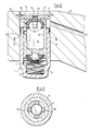
- a hydraulic lash adjuster 1 is mounted in a bore 2 of a rocker arm 3.
- the hydraulic lash adjuster 1 consists of an outer piston 4 which is closed at one end and which in a longitudinal bore with little play longitudinally displaceably receives the inner piston 5.
- the two pistons 4 and 5 enclose between them the high-pressure chamber 6, which is connected to the oil reservoir 8 provided in the inner piston 5 by a check valve 7 arranged in the inner piston 5.
- the hydraulic lash adjuster is supported with its end facing away from the high-pressure chamber 6 on a disk 9 which is inserted into the bore 2 and in turn is supported there against a snap ring 10.
- the disk 9 has, on its surface facing the hydraulic lash adjuster 1, recesses 11 which allow oil to pass into the oil reservoir 8.
- the oil supply to the hydraulic lash adjuster 1 takes place via the oil hole 12 in the rocker arm 3.
- the disc 9 has a central bore 13, into which the central pin 14 of a plastic part is inserted, which has clamping projections 15 which engage under radial prestress in the bore 16 of the inner piston 5 and thereby fix the disc 9 to the hydraulic play compensation element 1.
- the adhesion of the disk can be improved by the fact that the clamping projections 15 engage in a circumferential groove 17 of the bore 16.
- the clamping projections 15 are designed as a plurality of spring pulls which are distributed over the circumference and are curved radially outwards.
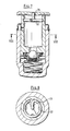
- the clamping projection is formed by a bead 18 which projects radially outwardly from a circumferential rim 19 which is connected by a plurality of spokes 20 to a central hub 21 which in turn carries the central pin 14, which in turn is inserted into the central bore 13 of the disk 9.
- FIGS. 5 and 6 differs from the previous one essentially only in that the bead 18 extends only over part of the peripheral regions lying between two successive spokes.
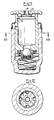
- a clamping projection is formed by a wire ring 22 which is open at a circumferential point and which at its one open end merges into a radially inwardly directed spoke 23 to which the axially extending central one is located Pin 24 connects.
- the additional component is in the form of a sheet metal part which, starting from a central plate 25, is enlarged in diameter in two successive stages 26 and 27 and ends in a circumferential ring 28 with a projecting collar 29.
- the sheet metal part is provided with openings 30 at several peripheral points in the area between the central plate 25 and the peripheral ring 28.
- the sheet metal part is attached to the disk 9 by an additional rivet 31 which is inserted into a bore in the central plate 25 and is pressed into the central bore 13 of the disk 9.
- FIGS. 11 and 12 differs from the previous one in that the openings 32 also interrupt the collar 29.
- a collar 33 is provided for fastening the sheet metal part 4, which collar is put through directly from the central plate 25.
Landscapes
- Engineering & Computer Science (AREA)
- Mechanical Engineering (AREA)
- General Engineering & Computer Science (AREA)
- Valve-Gear Or Valve Arrangements (AREA)
- Valve Device For Special Equipments (AREA)
Abstract
2.1. Hydraulische Spielausgleichselemente, die aus einem Außen (4)- und Innenkolben (5) bestehen, welche längsverschieblich ineinander angeordnet sind, werden in einer Längsbohrung (2) eines dem Ventiltrieb angehörenden Bauteiles (3) gelagert, wobei sich der Innenkolben (5) an einer in der Bohrung fixierten Scheibe (9) abstützt. Um Montagefehler zu vermeiden, soll eine Montageeinheit aus Spielausgleichselement und Scheibe geschaffen werden. 2.2. Um die Scheibe (9) fest aber lösbar mit dem Innenkolben (5) zu verbinden, greift sie mit unter radialer Vorspannung stehenden Klemmvorsprüngen (15) in die Bohrung (16) des Innenkolbens (5) ein. 2.3. Das Spielausgleichselement eignet sich, um in einfach herstellbare Durchgangsbohrungen von Kipphebeln eingesetzt zu werden.2.1. Hydraulic lash adjusters, which consist of an outer (4) - and inner piston (5), which are longitudinally displaceable one inside the other, are mounted in a longitudinal bore (2) of a component (3) belonging to the valve train, with the inner piston (5) on one supported disc (9) fixed in the bore. To avoid assembly errors, an assembly unit consisting of a play compensation element and washer should be created. 2.2. In order to connect the disk (9) firmly but detachably to the inner piston (5), it engages in the bore (16) of the inner piston (5) with clamping projections (15) under radial prestress. 2.3. The play compensation element is suitable for use in rocker arm through holes that are easy to manufacture.
Description
Die Erfindung betrifft ein hydraulisches Spielausgleichselement gemäß dem Oberbegriff des Anspruchs 1.The invention relates to a hydraulic lash adjuster according to the preamble of
Solche Spielausgleichselemente werden beispielsweise in Bohrungen von Kipphebeln angeordnet. Aus Fertigungsgründen führt man dabei die Bohrung im Kipphebel als durchgehende Bohrung aus, in der eine Scheibe angeordnet wird, die sich z.B. gegen einen Sprengring abstützt und die ihrerseits als Abstützung für das hydraulische Spielausgleichselement dient. Die Scheibe weist dabei in ihrer mit dem Spielausgleichselement zusammenwirkenden Fläche Vertiefungen auf, die es ermöglichen, daß Öl von außen in das Innere des Innenkolbens übertritt. Bei diesen bekannten Spielausgleichselementen war ihr Einbau in einen Kipphebel mit einigen Problemen behaftet. So mußte zunächst die Scheibe in die Bohrung eingesetzt werden, bevor das hydraulische Spielausgleichselement eingeführt werden konnte. Dabei konnte es geschehen, daß die Scheibe nach ihrem Einführen in die Bohrung wieder aus dieser herausfiel. Es konnte auch geschehen, daß die Scheibe um 180° verdreht eingesetzt wurde, so daß sie nicht mit ihren Vertiefungen gegen das Spielausgleichselement anlag, sondern mit einer Planfläche, die den Ölübertritt verhinderte. Letztlich was es auch nicht ausgeschlossen, daß das Einführen der Scheibe in die Bohrung überhaupt vergessen wurde. Es konnten somit alle die Probleme auftreten, die erfahrungsgemäß bei der Montage mehrerer separater Teile, die noch dazu richtungsabhängig montiert werden müssen, auftreten können.Such play compensation elements are arranged, for example, in bores of rocker arms. For manufacturing reasons, the bore in the rocker arm is designed as a continuous bore in which a disc is arranged, which is supported, for example, against a snap ring and which in turn serves as a support for the hydraulic play compensation element. In this case, the disk has depressions in its surface that cooperates with the play compensation element, which allow oil to pass from the outside into the interior of the inner piston. With these known play compensation elements, their installation in a rocker arm was fraught with some problems. So the disc had to be inserted into the hole before the hydraulic lash adjuster could be inserted. It could happen that the disk fell out of the hole after it was inserted into the hole. It could also happen that the disc was inserted rotated by 180 ° so that it did not rest with its recesses against the play compensation element, but with a flat surface that prevented the oil from being transferred. Ultimately, it also does not rule out that the insertion of the disc into the bore was forgotten at all. Thus, all the problems could arise that experience has shown when assembling several separate parts, which also have to be assembled depending on the direction.
Der Erfindung liegt die Aufgabe zugrunde, mit einfachsten technischen Mitteln eine Montageeinheit, bestehend aus dem hydraulischen Spielausgleichselement einerseits und der Scheibe andererseits zu schaffen und damit Montagefehler auszuschalten.The invention has for its object to create a mounting unit consisting of the hydraulic lash adjuster on the one hand and the disc on the other hand with the simplest technical means and thus eliminate assembly errors.
Diese Aufgabe löst die Erfindung dadurch, daß die Scheibe bei Anlage an dem dem Druckraum abgwandten Ende des Innenkolbens mit radial federnden Klemmvorsprüngen in die Bohrung des Innenkolbens eingreift. Auf diese Weise wird eine kraftschlüssige Verbindung zwischen dem hydraulischen Spielausgleichselement und der Scheibe erreicht.The invention solves this problem in that the disk engages in the bore of the inner piston with radially resilient clamping projections when it contacts the end of the inner piston facing away from the pressure chamber. In this way, a non-positive connection between the hydraulic lash adjuster and the disc is achieved.
Soll ein noch verbesserter Zusammenhalt zwischen Spielausgleichselement und Scheibe erreicht werden, kann in der Bohrung des Innenkolbens eine Umfansrille vorgesehen werden, in die die Klemmvorsprünge eingreifen, wodurch eine formschlüssige Verbindung hergestellt wird.If an even better cohesion between the lash adjuster and the washer is to be achieved, a circumferential groove can be provided in the bore of the inner piston, into which the clamping projections engage, whereby a positive connection is established.
Zweckmäßige Ausbildungen der Klemmvorsprünge und deren Verbindung mit der Scheibe sind in den weiteren Unteransprüchen aufgeführt.Appropriate training of the clamping projections and their connection to the disc are listed in the further subclaims.
In den Zeichnungen sind Ausführungsbeispiele der Erfindung dargestellt. Es zeigen:
- Fig. 1 eine Längsschnitt durch ein hydraulisches Spielausgleichselement gemäß der Erfindung,
- Fig. 2 einen Querschnitt nach Linie II-II der
Figur 1 und - Fig. 3 bis 12 jeweils Längs- und Querschnitte durch weitere Varianten der Erfindung
- 1 is a longitudinal section through a hydraulic lash adjuster according to the invention,
- Fig. 2 shows a cross section along line II-II of Figure 1 and
- 3 to 12 each longitudinal and cross sections through further variants of the invention
In den Fig. 1 und 2 ist eine Ausführung dargestellt, bei der ein hydraulisches Spielausgleichselement 1 in einer Bohrung 2 eines Kipphebels 3 gelagert ist. Das hyraulische Spielausgleichselement 1 besteht aus einem an seinem einen Ende verschlossenen Außenkolben 4, der in einer Längsbohrung mit geringem Spiel längsverschieblich den Innenkolben 5 aufnimmt. Die beiden Kolben 4 und 5 schließen zwischen sich den Hochdruckraum 6 ein, der durch ein im Innenkolben 5 angeordnetes Rückschlagventil 7 mit dem im Innenkolben 5 vorgesehenen Ölvorratsraum 8 verbunden ist.1 and 2, an embodiment is shown in which a
Das hydraulische Spielausgleichselement stützt sich mit seinem dem Hochdruckraum 6 abgewandten Ende an einer Scheibe 9 ab, die in die Bohrung 2 eingesetzt ist und sich ihrerseits dort gegen einen Sprengring 10 abstützt. Die Scheibe 9 weist an ihrer dem hydraulischen Spielausgleichselement 1 zugewandten Fläche eingeformte Vertiefungen 11 auf, die den Übertritt von Öl in den Ölvorratsraum 8 ermöglichen. Die Ölzufuhr zu dem hydraulischen Spielausgleichselement 1 erfolgt über die Ölbohrung 12 im Kipphebel 3.The hydraulic lash adjuster is supported with its end facing away from the high-pressure chamber 6 on a
Die Scheibe 9 weist eine zentrale Bohrung 13 auf, in welche der zentrale Zapfen 14 eines Kunststoffteiles eingesetzt ist, welches Klemmvorsprünge 15 aufweist, die unter radialer Vorspannung in die Bohrung 16 des Innenkolbens 5 eingreifen und dadurch die Scheibe 9 an dem hydraulischen Spielausgleichselment 1 fixieren. Verbessert werden kann die Haftung der Scheibe dadurch, daß die Klemmvorsprünge 15 in eine Umfangsrille 17 der Bohrung 16 eingreifen. Die Klemmvorsprünge 15 sind in diesem Falle als mehrere über den Umfang verteilte, radial nach außen gewölbte Federzugen ausgebildet.The
Bie der in den Fig. 3 und 4 dargestellten Ausführung ist der Klemmvorsprung durch einen Wulst 18 gebildet, der einen Umfangskranz 19 radial nach außen überragt, welcher durch mehrere Speichen 20 mit einer zentralen Nabe 21 verbunden ist, die ihrerseits den zentralen Zapfen 14 trägt, der wiederum in die zentrale Bohrung 13 der Scheibe 9 eingesetzt ist.In the embodiment shown in FIGS. 3 and 4, the clamping projection is formed by a
Die in den Fig. 5 und 6 dargestellte Ausführung unterscheidet sich von der vorhergehenden im wesentlichen nur dadurch, daß der Wulst 18 sich nur über einen Teil der zwischen zwei aufeinanderfolgende Speichen liegenden Umfangsbereiche erstreckt.The embodiment shown in FIGS. 5 and 6 differs from the previous one essentially only in that the
Während die bisher beschriebenen Ausführungen als Kunststoffteile ausgebildet waren, handelt, es sich bei den folgenden Varianten um Metallteile. In den Fig. 7 und 8 ist eine Ausführung gezeigt, bei welcher ein Klemmvorsprung durch einen an einer Umfangsstelle offenen Drahtring 22 gebildet ist, der an seinem einen offenen Ende in eine radial nach innen gerichtete Speiche 23 übergeht, an die sich der axial verlaufende zentrale Zapfen 24 anschließt.While the designs described so far were designed as plastic parts, the following variants are metal parts. 7 and 8, an embodiment is shown in which a clamping projection is formed by a
Bei der Ausführung nach den Fig. 9 und 10 ist das zusätzliche Bauteil als Blechziehteil ausgebildet, das ausgehend von einer zentralen Platte 25 in zwei aufeinanderfolgenden Stufen 26 und 27 im Durchmesser vergrößert ist und in einem Umfangskranz 28 mit einem vorspringenden Kragen 29 endet. Um den Öldurchtritt zu ermöglichen und zur gleichzeitigen Verbesserung der Federung ist das Blechziehteil an mehreren Umfangsstellen in dem Bereich zwischen der zentralen Platte 25 und dem Umfangskranz 28 mit Durchbrüchen 30 versehen. Die Befestigung des Blechziehteiles an der Scheibe 9 erfolgt in diesem Falle durch ein zusätzliches Niet 31, welches in eine Bohrung der zentralen Platte 25 eingesetzt und in die zentrale Bohrung 13 der Scheibe 9 eingepreßt ist.In the embodiment according to FIGS. 9 and 10, the additional component is in the form of a sheet metal part which, starting from a central plate 25, is enlarged in diameter in two successive stages 26 and 27 and ends in a
Die in den Fig.11 und 12 dargestellte Ausführung unterscheidet sich von der vorhergehenden dadurch, daß die Durchbrüche 32 auch den Kragen 29 unterbrechen. Andererseits ist zur Befestigung des Blechziehteiles 4 ein Kragen 33 vorgesehen, der unmittelbar von der zentralen Platte 25 ausgehend durchgestellt ist.The embodiment shown in FIGS. 11 and 12 differs from the previous one in that the
Claims (15)
Applications Claiming Priority (2)
| Application Number | Priority Date | Filing Date | Title |
|---|---|---|---|
| DE3706006 | 1987-02-25 | ||
| DE19873706006 DE3706006A1 (en) | 1987-02-25 | 1987-02-25 | HYDRAULIC GAME COMPENSATION ELEMENT FOR VALVE CONTROLS ON COMBUSTION ENGINES |
Publications (2)
| Publication Number | Publication Date |
|---|---|
| EP0280888A1 true EP0280888A1 (en) | 1988-09-07 |
| EP0280888B1 EP0280888B1 (en) | 1990-09-05 |
Family
ID=6321716
Family Applications (1)
| Application Number | Title | Priority Date | Filing Date |
|---|---|---|---|
| EP88101424A Expired - Lifetime EP0280888B1 (en) | 1987-02-25 | 1988-02-02 | Hydraulic lash adjuster for the valve drives of internal-combustion engines |
Country Status (5)
| Country | Link |
|---|---|
| US (1) | US4800851A (en) |
| EP (1) | EP0280888B1 (en) |
| JP (1) | JPH0689657B2 (en) |
| DE (2) | DE3706006A1 (en) |
| ES (1) | ES2016997B3 (en) |
Families Citing this family (11)
| Publication number | Priority date | Publication date | Assignee | Title |
|---|---|---|---|---|
| DE4030987A1 (en) * | 1990-10-01 | 1992-04-02 | Schaeffler Waelzlager Kg | AUTOMATICALLY HYDRAULICALLY ADJUSTING VALVE |
| GB2254109B (en) * | 1991-03-29 | 1994-10-12 | Fuji Heavy Ind Ltd | Valve mechanism for an internal combustion engine |
| US5622146A (en) * | 1993-06-18 | 1997-04-22 | Ina Walzlager Schaeffler Kg | Finger lever for actuating gas exchange valves |
| DE19503699A1 (en) * | 1995-02-04 | 1996-08-08 | Schaeffler Waelzlager Kg | First filling of hydraulic valve drive tappet with hydraulic oil |
| DE19610107A1 (en) * | 1996-03-15 | 1997-09-18 | Schaeffler Waelzlager Kg | Rocker arm or rocker arm with a valve lash adjuster |
| DE19629203B4 (en) * | 1996-07-19 | 2014-05-22 | Schaeffler Technologies Gmbh & Co. Kg | Hydraulic lash adjuster |
| DE19738811A1 (en) * | 1997-09-05 | 1999-03-11 | Schaeffler Waelzlager Ohg | Engine valve-gear rocker |
| DE19748162A1 (en) * | 1997-10-31 | 1999-05-06 | Audi Ag | Valve tappet with hydraulic valve clearance leveling element |
| US6044813A (en) * | 1997-12-09 | 2000-04-04 | Siemens Automotive Corporation | Electromagnetic actuator with detached lower collar to align with cylinder head bore |
| WO2001020150A1 (en) * | 1999-09-17 | 2001-03-22 | Diesel Engine Retarders, Inc. | Captive volume accumulator for a lost motion system |
| DE102005059700A1 (en) * | 2005-12-14 | 2007-06-21 | Schaeffler Kg | Part for valve drive of combustion engine has hydraulic play compensating element in seat, thin-walled body supporting pressure piston against base of seat, spring collar or tongues jutting out and lying against lining of piston |
Citations (2)
| Publication number | Priority date | Publication date | Assignee | Title |
|---|---|---|---|---|
| FR2370858A1 (en) * | 1976-11-16 | 1978-06-09 | Motomak | HYDRAULIC RELEASE ELEMENT FOR INTERNAL COMBUSTION ENGINES |
| FR2540554A1 (en) * | 1983-02-09 | 1984-08-10 | Motomak | INTERNAL ELEMENT FOR VALVE HYDRAULIC PLAY COMPENSATOR ELEMENT FOR INTERNAL COMBUSTION ENGINES |
Family Cites Families (6)
| Publication number | Priority date | Publication date | Assignee | Title |
|---|---|---|---|---|
| JPH029046Y2 (en) * | 1984-08-29 | 1990-03-06 | ||
| JPS6165209U (en) * | 1984-10-04 | 1986-05-02 | ||
| DE3541198A1 (en) * | 1985-11-21 | 1987-05-27 | Motomak | HYDRAULIC GAME COMPENSATION DEVICE |
| DE3605645A1 (en) * | 1986-02-21 | 1987-08-27 | Motomak | INTERNAL ELEMENT FOR A HYDRAULIC VALVE COMPENSATION COMPENSATING ELEMENT FOR COMBUSTION ENGINES |
| DE3606536A1 (en) * | 1986-02-28 | 1987-09-03 | Motomak | INTERNAL ELEMENT FOR A HYDRAULIC VALVE COMPENSATION COMPENSATING ELEMENT FOR COMBUSTION ENGINES |
| DE3614258A1 (en) * | 1986-04-26 | 1987-10-29 | Motomak | HYDRAULIC VALVE COMPENSATION COMPENSATION DEVICE FOR COMBUSTION ENGINES |
-
1987
- 1987-02-25 DE DE19873706006 patent/DE3706006A1/en not_active Withdrawn
-
1988
- 1988-02-02 ES ES88101424T patent/ES2016997B3/en not_active Expired - Lifetime
- 1988-02-02 DE DE8888101424T patent/DE3860536D1/en not_active Expired - Lifetime
- 1988-02-02 EP EP88101424A patent/EP0280888B1/en not_active Expired - Lifetime
- 1988-02-05 US US07/152,540 patent/US4800851A/en not_active Expired - Fee Related
- 1988-02-22 JP JP63037695A patent/JPH0689657B2/en not_active Expired - Lifetime
Patent Citations (2)
| Publication number | Priority date | Publication date | Assignee | Title |
|---|---|---|---|---|
| FR2370858A1 (en) * | 1976-11-16 | 1978-06-09 | Motomak | HYDRAULIC RELEASE ELEMENT FOR INTERNAL COMBUSTION ENGINES |
| FR2540554A1 (en) * | 1983-02-09 | 1984-08-10 | Motomak | INTERNAL ELEMENT FOR VALVE HYDRAULIC PLAY COMPENSATOR ELEMENT FOR INTERNAL COMBUSTION ENGINES |
Also Published As
| Publication number | Publication date |
|---|---|
| ES2016997B3 (en) | 1990-12-16 |
| US4800851A (en) | 1989-01-31 |
| EP0280888B1 (en) | 1990-09-05 |
| DE3860536D1 (en) | 1990-10-11 |
| JPH0689657B2 (en) | 1994-11-09 |
| JPS63227910A (en) | 1988-09-22 |
| DE3706006A1 (en) | 1988-09-08 |
Similar Documents
| Publication | Publication Date | Title |
|---|---|---|
| EP0223898B1 (en) | Hydraulic lash adjusting device | |
| EP0301267B1 (en) | Ball joint placed between a rocker arm and a valve shaft in an internal-combustion engine | |
| EP1778988B1 (en) | Ball joint | |
| EP0280888B1 (en) | Hydraulic lash adjuster for the valve drives of internal-combustion engines | |
| EP0244558B1 (en) | Hydraulic valve lash adjusting device for an internal-combustion engine | |
| DE19742361A1 (en) | Elastic joint body | |
| DE10110914A1 (en) | Valve train of an internal combustion engine with a switchable, rotationally symmetrical component | |
| DE3438918A1 (en) | DRIVER CONNECTION BETWEEN A SHAFT AND A HUB | |
| EP0745757A1 (en) | Assembled camshaft, particularly for internal combustion engines | |
| EP0516962A1 (en) | Mechanical valve tappet for an internal combustion engine | |
| DE3418804A1 (en) | PROTECTIVE CUFF FOR CYLINDRICAL PARTS, ESPECIALLY FOR A BOLT GUIDE FOR A PART COVER DISC BRAKE | |
| DE4340035B4 (en) | Mechanical bucket tappet | |
| DE2535177C3 (en) | Caster | |
| DE19834677C2 (en) | Ball joint, in particular for steering and axle linkages of motor vehicles | |
| DE3823745A1 (en) | Flywheel with vibration damper | |
| EP0380770A1 (en) | Valve stem seal | |
| DE2136844C3 (en) | Storage of manual shift levers for motor vehicles | |
| DE4401011C2 (en) | Built camshaft | |
| EP0234343B1 (en) | Internal element for a hydraulic valve play adjusting element for internal-combustion engines | |
| DE19706441A1 (en) | Tilting or turning lever for valve drive of internal combustion engine | |
| EP0235599B1 (en) | Internal element for a hydraulic valve play adjusting element for internal-combustion engines | |
| EP0757162B1 (en) | Cup-shaped tappet for an internal combustion engine | |
| EP0234022B1 (en) | Internal element for a hydraulic lash adjusting element for internal combustion engines | |
| DE2360803C3 (en) | check valve | |
| DE4406409A1 (en) | Mechanical tappet for IC engine cylinder heads |
Legal Events
| Date | Code | Title | Description |
|---|---|---|---|
| PUAI | Public reference made under article 153(3) epc to a published international application that has entered the european phase |
Free format text: ORIGINAL CODE: 0009012 |
|
| 17P | Request for examination filed |
Effective date: 19880202 |
|
| AK | Designated contracting states |
Kind code of ref document: A1 Designated state(s): DE ES FR GB IT |
|
| 17Q | First examination report despatched |
Effective date: 19900221 |
|
| ITF | It: translation for a ep patent filed |
Owner name: DE DOMINICIS & MAYER S.R.L. |
|
| GRAA | (expected) grant |
Free format text: ORIGINAL CODE: 0009210 |
|
| AK | Designated contracting states |
Kind code of ref document: B1 Designated state(s): DE ES FR GB IT |
|
| GBT | Gb: translation of ep patent filed (gb section 77(6)(a)/1977) | ||
| REF | Corresponds to: |
Ref document number: 3860536 Country of ref document: DE Date of ref document: 19901011 |
|
| ET | Fr: translation filed | ||
| PLBE | No opposition filed within time limit |
Free format text: ORIGINAL CODE: 0009261 |
|
| STAA | Information on the status of an ep patent application or granted ep patent |
Free format text: STATUS: NO OPPOSITION FILED WITHIN TIME LIMIT |
|
| 26N | No opposition filed | ||
| PGFP | Annual fee paid to national office [announced via postgrant information from national office to epo] |
Ref country code: ES Payment date: 19920211 Year of fee payment: 5 |
|
| ITTA | It: last paid annual fee | ||
| PGFP | Annual fee paid to national office [announced via postgrant information from national office to epo] |
Ref country code: GB Payment date: 19930125 Year of fee payment: 6 |
|
| PG25 | Lapsed in a contracting state [announced via postgrant information from national office to epo] |
Ref country code: ES Free format text: LAPSE BECAUSE OF NON-PAYMENT OF DUE FEES Effective date: 19930203 |
|
| PG25 | Lapsed in a contracting state [announced via postgrant information from national office to epo] |
Ref country code: GB Effective date: 19940202 |
|
| PGFP | Annual fee paid to national office [announced via postgrant information from national office to epo] |
Ref country code: FR Payment date: 19940204 Year of fee payment: 7 |
|
| GBPC | Gb: european patent ceased through non-payment of renewal fee |
Effective date: 19940202 |
|
| PG25 | Lapsed in a contracting state [announced via postgrant information from national office to epo] |
Ref country code: FR Effective date: 19951031 |
|
| REG | Reference to a national code |
Ref country code: FR Ref legal event code: ST |
|
| REG | Reference to a national code |
Ref country code: ES Ref legal event code: FD2A Effective date: 19990301 |
|
| PGFP | Annual fee paid to national office [announced via postgrant information from national office to epo] |
Ref country code: DE Payment date: 20010217 Year of fee payment: 14 |
|
| PG25 | Lapsed in a contracting state [announced via postgrant information from national office to epo] |
Ref country code: DE Free format text: LAPSE BECAUSE OF NON-PAYMENT OF DUE FEES Effective date: 20020903 |
|
| PG25 | Lapsed in a contracting state [announced via postgrant information from national office to epo] |
Ref country code: IT Free format text: LAPSE BECAUSE OF NON-PAYMENT OF DUE FEES;WARNING: LAPSES OF ITALIAN PATENTS WITH EFFECTIVE DATE BEFORE 2007 MAY HAVE OCCURRED AT ANY TIME BEFORE 2007. THE CORRECT EFFECTIVE DATE MAY BE DIFFERENT FROM THE ONE RECORDED. Effective date: 20050202 |