EP0280435B1 - Adjustable quick release magnetic holding assembly - Google Patents
Adjustable quick release magnetic holding assembly Download PDFInfo
- Publication number
- EP0280435B1 EP0280435B1 EP88301069A EP88301069A EP0280435B1 EP 0280435 B1 EP0280435 B1 EP 0280435B1 EP 88301069 A EP88301069 A EP 88301069A EP 88301069 A EP88301069 A EP 88301069A EP 0280435 B1 EP0280435 B1 EP 0280435B1
- Authority
- EP
- European Patent Office
- Prior art keywords
- magnetic
- mount
- assembly
- holding assembly
- attachment plate
- Prior art date
- Legal status (The legal status is an assumption and is not a legal conclusion. Google has not performed a legal analysis and makes no representation as to the accuracy of the status listed.)
- Expired - Lifetime
Links
Images


Classifications
-
- H—ELECTRICITY
- H01—ELECTRIC ELEMENTS
- H01F—MAGNETS; INDUCTANCES; TRANSFORMERS; SELECTION OF MATERIALS FOR THEIR MAGNETIC PROPERTIES
- H01F7/00—Magnets
- H01F7/02—Permanent magnets [PM]
-
- B—PERFORMING OPERATIONS; TRANSPORTING
- B63—SHIPS OR OTHER WATERBORNE VESSELS; RELATED EQUIPMENT
- B63H—MARINE PROPULSION OR STEERING
- B63H8/00—Sail or rigging arrangements specially adapted for water sports boards, e.g. for windsurfing or kitesurfing
- B63H8/50—Accessories, e.g. repair kits or kite launching aids
- B63H8/54—Arrangements for connecting the user or the harness to the wishbone, e.g. trapeze lines or handgrips
-
- B—PERFORMING OPERATIONS; TRANSPORTING
- B63—SHIPS OR OTHER WATERBORNE VESSELS; RELATED EQUIPMENT
- B63H—MARINE PROPULSION OR STEERING
- B63H8/00—Sail or rigging arrangements specially adapted for water sports boards, e.g. for windsurfing or kitesurfing
- B63H8/50—Accessories, e.g. repair kits or kite launching aids
- B63H8/56—Devices to distribute the user's load, e.g. harnesses
- B63H8/58—Spreader bars; Hook connection arrangements
-
- H—ELECTRICITY
- H01—ELECTRIC ELEMENTS
- H01F—MAGNETS; INDUCTANCES; TRANSFORMERS; SELECTION OF MATERIALS FOR THEIR MAGNETIC PROPERTIES
- H01F7/00—Magnets
- H01F7/02—Permanent magnets [PM]
- H01F7/0205—Magnetic circuits with PM in general
- H01F7/0226—PM with variable field strength
-
- Y—GENERAL TAGGING OF NEW TECHNOLOGICAL DEVELOPMENTS; GENERAL TAGGING OF CROSS-SECTIONAL TECHNOLOGIES SPANNING OVER SEVERAL SECTIONS OF THE IPC; TECHNICAL SUBJECTS COVERED BY FORMER USPC CROSS-REFERENCE ART COLLECTIONS [XRACs] AND DIGESTS
- Y10—TECHNICAL SUBJECTS COVERED BY FORMER USPC
- Y10T—TECHNICAL SUBJECTS COVERED BY FORMER US CLASSIFICATION
- Y10T24/00—Buckles, buttons, clasps, etc.
- Y10T24/32—Buckles, buttons, clasps, etc. having magnetic fastener
-
- Y—GENERAL TAGGING OF NEW TECHNOLOGICAL DEVELOPMENTS; GENERAL TAGGING OF CROSS-SECTIONAL TECHNOLOGIES SPANNING OVER SEVERAL SECTIONS OF THE IPC; TECHNICAL SUBJECTS COVERED BY FORMER USPC CROSS-REFERENCE ART COLLECTIONS [XRACs] AND DIGESTS
- Y10—TECHNICAL SUBJECTS COVERED BY FORMER USPC
- Y10T—TECHNICAL SUBJECTS COVERED BY FORMER US CLASSIFICATION
- Y10T292/00—Closure fasteners
- Y10T292/11—Magnetic
Definitions
- This invention relates to magnetic holding assemblies but more particularly to an adjustable strength, magnetic holding assembly which takes advantage of the marked dichotomy between the comparatively strong normal component and the comparatively weak sheer component of the magnetic locking force.
- Specific applications include windsurfer/board sailing harnesses, ski bindings, trapeze harnesses and other weight support systems requiring a variable strength locking mechanism combined with a quick release capability.
- Magnetic latches are used in a variety of applications ranging from industrial electromagnetic coupling devices to cupboard and refrigerator latches. These invariably make use of the comparatively strong holding force in the direction of the magnetic flux lines. None of these devices incorporate a combined adjustable and safety release magnetic locking mechanism.
- GB-A-444786 discloses a magnetic holder and support, particularly for use with electric lamps, which will adhere in any position to objects made of ferro-magnetic materials.
- the support and holder are provided with permanent bar magnets and soft iron pole shoes and a short-circuiting device.
- the short circuiting device is provided in the space between the pole shoes and the bar magnets, and is movable such that the magnetic holding assembly is configured to either magnetically attract or not magnetically attract a ferro-magnetic material.
- the present invention provides a magnetic holding assembly, comprising: a holding and support assembly having an element made of magnetic material separated by a non-magnetic spacer from a permanent magnet positioned near said element, said magnet being magnetically coupled with said element; characterised in that the holding assembly further comprises: an attachment plate with a section thereof made of magnetic material, said section being magnetically coupled or couplable to the holding and support assembly which is adapted magnetically to hold the attachment plate thereon, whereby said section, element, non-magnetic spacer and permanent magnet form a magnetic circuit; and adjusting means including a material which is magnetically coupled to the permanent magnet for adjusting the magnetic coupling between said permanent magnet, element and said section of said attachment plate made of magnetic material by varying the separation between the permanent magnet and at least one of said magnetically coupled materials in the holding and support assembly in the direction of the magnetic flux, such that the intensity of the magnetic holding force between said attachment plate and said magnetic holding and support assembly can be adjusted whereby the magnetic holding assembly has variable strength.
- the magnetic holding assembly is suitable for use in a quick release machanism for windsurfer/sailing board body support harnesses. All available body harnesses make use of a hook affixed to a spreader bar. To use the harness, the board sailer hooks onto a looped line hanging from the wishbone of the windsurfer board. The pull of the sail is then transferred to the torso of the sailor who leans backward to achieve a lever arm balance between the vertical lift of the sail and the downward pull of gravity. To free himself from the looped line (and hence the wishbone and sail), the board sailor must pull forward on the wishbone with his arms.
- the holding assembly provides a convenient mechanism for detachment while sailing under controlled conditions with full tension on the support harness.
- the board sailor dips his body slightly causing the wishbone attachment line to jerk upward on the harness hook which is attached via a magnetic holding plate to the spreader bar.
- the hook plate assembly then slides past the magnet fixed to the spreader bar, pivots under tension from the loop line and subsequently releases the line.
- the line falls free and the board sailor is detached from the wishbone and sail.
- An elastic cord quickly returns the hook plate assembly to the magnetic assembly attached to the spreader bar and the board sailor is ready to be reattached to the wishbone line.
- Adjustment of the locking intensity can be affected by the controlled in-out movement of a magnet or magnetic material which alters the magnetic flux of a pre-designed magnetic circuit within the assembly. And hence, magnetic flux within the locking portion of the circuit leads to intensification of the in line holding force between the magnetic assembly and an external holding or locking plate; the decreased magnetic flux leads to the opposite response.
- the quick release capability of the latch is based on the low resistance of magnetically coupled materials to shearing motions normal to the lines of magnetic flux. Whereas considerable force is required to separate the magnetically coupled materials in the direction of magnetic flux, a much lower frictional force must be overcome in order to slide the materials apart in a direction normal to the flux lines.
- the frictional force is proportional to the in-line magnetic force and to the coefficient of friction, where the coefficient of static friction is more than the coefficient of sliding friction.
- a slight body motion is required to initiate the quick release sheer mode and, once initiated, the release continues relatively unimpeded.
- the elastic return mechanism is incorporated into the design in order to bring the attachment plate to its starting (normal) configuration.
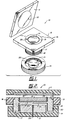
- FIG. 1 gives a general overview of the basic components that form part of the magnetic holding assembly of the present invention.
- the variable strength magnetic holding assembly is comprised of three main components. These include an attachment plate 11 having a disk like section 12 centrally positioned therein and made of a magnetic material.
- a magnetic holding and support assembly 13 is adapted to magnetically hold the attachment plate 11 thereon.
- This assembly 13 is comprised of permanent magnet 14 surrounded by a non-magnetic ring-shaped bonding material 26 and a ring-shaped mount 15 positioned within a non-magnetic holding plate 16.
- the bonding material 26 also act as a spacer to prevent sideway flux leakage between magnet 14 and mount 15.
- Ring-shaped mount 15 extends below mounting plate 16 to form tubular element 17.
- Tubular elements 17 can be provided with a series of threads 18 adapted to permit the securing of an adjustment knob 19.
- Knob 19 has a series of threads 20 and a disk like section 21 having an exterior diameter smaller in cross-sectional area than the interior diameter of tubular element 17. The use of cams to replace the threads has been found to be preferable. Such a cam design is shown in Figure 8.
- the ring shaped mount 15 and disk like element 21 of adjustment knob 19 are also made of magnetic material. The particular construction of the magnetic holding assembly will, of course, vary according to the specific type of embodiment used.
- the structure shown in Figure 1 discloses the preferred embodiment of the present invention.
- the elements made of magnetic material form with permanent magnet 14 a magnetic circuit.
- the variation of the separation between the permanent magnet 14 and at least one of the elements made of magnetic material, in the direction of the magnetic flux lines, will be such that the magnetic holding force between the attachment plate element 12 and the magnetic holding and support assembly can be adjusted.
- Attachment plate 11 is made of a non-magnetic material such as plastic or aluminum.
- the disk like element 12 is made of relatively thin magnetic material which forms with the attachment plate a relatively flat surface adapted to be magnetically held onto the magnetic holding and support assembly 13.
- the magnetic holding and support assembly 13 comprises a permanent magnet 14 which is secured by means of non-magnetic bounding material 26 within a circular two chamber ring 15 made of magnetic material.
- the upper surface of the magnet 14 and encompassing ring 15 present a flat surface for attachment to disk 12 and attachment plate 11.
- the lower surface of the magnet can be supported by a bridge 23 that separates the two chambers of the ring.
- the lower section of ring mount 15 extends downwardly from support plate 16 to form a tubular element 17 having threads 18 which will mate with threads 20 of adjustment knob 19 as indicated before, threads 18 and 20 can be replaced by a cam adjusting system.
- Adjustment knob 19 can be made of non-magnetic material such as plastic or wood.
- Knob 19 is provided with a disk like element 21 made of magnetic material and having a diameter slightly smaller than the inside diameter of the lower chamber of ring 15.
- Permanent magnet 14 along with element 12, 21 and ring 15 are made of magnetic material and form a magnetic circuit.
- the central axes of magnet 14 and disk like element 21 are aligned such that when adjustment knob 19 is rotated, disk-like element 21 is free to move along the axial direction of permanent magnet 14 and ring 15 of the magnetic holding and support assembly 13.
- the adjustment of the locking intensity is affected by the controlled movement of element 21 which alters the magnetic flux of the magnetic circuit present in the assembly.
- the tightening of adjustment knob 19 and hence the reduction of the air gap between magnet 14 and element 21 results in an enhanced magnetic flux within the locking portion of the circuit and, therefore, leads to intensification of the in-line holding force between attachment plate 11 and holding assembly 13.
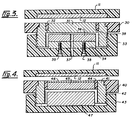
- FIG. 3 we have shown a sectional view of a magnetic holding assembly according a second embodiment of the present invention.
- the locking plate 11 remains unchanged, however, the magnetic holding and support assembly 30 no longer retains the permanent magnet.
- This assembly now includes a cylindrical shaped mount 31 made of magnetic material which except for a ring shaped spacer 32, is integrally complete. Gap 38 between spacer 32 and the lower chamber of mount 31 is very small. This gap can however be filled by spacer 32 as shown in Figure 4 with spacer 44.
- adjustment knob 33 includes an element made of magnetic material 34 secured to adjustment knob 33 by means of a set of non-magnetic screws 35.
- a permanent magnet 36 is mounted onto element 34 and secured thereto by means of a non-magnetic bonding material.
- Adjustment knob 33 will effect the magnetic coupling between permanent magnet 36 and elements 12, 31 and 34 which are all made of magnetic material. The variation in the magnetic coupling will therefore effect the magnetic holding force between locking plate 11 and magnetic holding and support assembly 30. Adjustment knob 33 is also provided with a vent 37 to permit the escape of water or air present between adjustment knob 33 and element 31.
- the magnetic holding and support assembly 40 is comprised of a ring shaped mount 41 made of magnetic material and having a series of threads 42 to permit adjustment knob 43 to be threaded thereon.
- a non-magnetic ring shaped spacer 44 surrounds the permanent magnet 45 and is located within ring shaped mount 41.
- a thin disk like element 46 can be located inside the ring shaped spacer 44 and positioned on permanent magnet 45.
- a disk like element 47 made of magnetic material is secured on adjustment knob 43 by means of bonding material or non-magnetic screws.
- the permanent magnet and at least one of the elements of magnetic material are aligned with respect to each other along the same central axes such that the rotation of the adjustment knob controls the relative movement of either permanent magnet or a segment of magnetic material within the holding assembly and thus permit a variation of the magnetic holding force between the attachment plate and the magnetic holding assembly.
- FIG. 5 and 6 we have shown perspective views of the magnetic holding assembly of the present invention as can be used on a windsurfer harness gear.
- the standard type of harness consists of some form of hook permanently attached to a "spreader bar". This spreader bar helps distribute the load along the board sailor's torso and is usually constructed of metal, wood or plastic depending on the brand. With this sort of arrangement, the rider's body will tend to be positioned perpendicular to a support line connecting the hook to the "wishbone" of the windsurfer.
- FIG. 100 An improved windsurfer harness using the magnetic holding and support assembly of the present invention is shown generally at reference numeral 100 in Figures 5 and 6.
- the hook 101 which is adapted to be connected by means of a support line to the wishbone of the windsurfer, is secured or permanently attached to the attachment plate 102 which forms part of the magnetic holding and support assembly.
- the spreader bar which helps distribute the load is shown at reference numeral 103 and can be worn by the board sailor by means of a pair of straps 104. Each strap 104 is fed through an opening 106 located at the edge of the spreader bar 103.
- the central section 107 of spreader bar 103 is adapted to receive the magnetic holding and support assembly 108 which includes a mounting plate 109 made of non-magnetic material such as plastic or aluminum, a ring shaped mount 110 made of magnetic material and a permanent magnet 111 centrally located therein. Attachment plate 102 is provided with a central section 120 made of magnetic material.
- the attachment plate 102 is pivotably and slideably mounted onto central section 107 of spreader bar 103 by means of looped strap 105 which is fed through side opening 112 of central section 107 and side opening 113 of attachment plate 102.
- This securing arrangment will permit attachment plate 102 to slide or pivot with respect to magnetic holding and support assembly 108 according to the type of force being exerted onto hook 101.
- a line 114 having elastomeric properties is led from one side of section 107 through a cavity 115 within attachment plate 102 to the opposite side of section 107, as shown by the phantom lines, cavity 115 has rounded edges.
- Line 114 will permit line 114 to slide towards the pivot point as plate 102 pivots and will facilitate the unhooking of the support line which is attached to the wishbone of the windsurfer.
- Line 114 is shown in Figure 5 in its stretched condition and in Figure 6 in its unstretched condition.
- the line can consist of simple bungie cord.
- FIG. 7 we have shown a front view of the harness arrangement shown in Figure 5 and 6. This view shows the location of adjustment knob 116 and also the path taken by strap 104 through spreader bar 103.
- the board sailor's spreader bar would be used as a regular windsurfer spreader bar, i.e. with his body generally perpendicular to the support line connecting hook 101 to the wishbone of the windsurfer.
- attachment plate 102 would remain in position since magnetic coupling is strongest in the direction normal to the plane of attachment plate 102 and holding and support assembly 108. Accordingly, considerable force would be required to separate the magnetically coupled materials in the direction of magnetic flux, whereas much lower frictional force must be overcome in order to slide attachment plate 102 over holding and support plate 108. This movement being in the direction normal to the flux line. Accordingly, to uncouple, the rider simply causes the hook to slide perpendicularly to the direct line-of-pull (i.e.
- FIG 8 shows a partially sectioned exploded view of another embodiment of the adjustment knob used with the magnetic holding and support assembly.
- Adjustment knob 150 includes a series of raised prongs 151 which are adapted to ride over a corresponding number of notched inclined planes 152 and would in effect replace the treaded arrangement 18 of cylindrical extension 17 showed Figures 1 and 2, as well as the threads of ring-shaped mount 31 and 41 shown Figures 3 and 4 respectively.
- the magnetic coupling between adjustment knob 150 and cylindrical extention 153 is so strong as to prevent accidental separation of these parts.
Landscapes
- Engineering & Computer Science (AREA)
- Mechanical Engineering (AREA)
- Electromagnetism (AREA)
- Power Engineering (AREA)
- Chemical & Material Sciences (AREA)
- Combustion & Propulsion (AREA)
- Physics & Mathematics (AREA)
- Ocean & Marine Engineering (AREA)
- Magnetic Treatment Devices (AREA)
- Braking Arrangements (AREA)
- Magnetic Resonance Imaging Apparatus (AREA)
- Jigs For Machine Tools (AREA)
- Manipulator (AREA)
- Buckles (AREA)
Abstract
Description
- This invention relates to magnetic holding assemblies but more particularly to an adjustable strength, magnetic holding assembly which takes advantage of the marked dichotomy between the comparatively strong normal component and the comparatively weak sheer component of the magnetic locking force. Specific applications include windsurfer/board sailing harnesses, ski bindings, trapeze harnesses and other weight support systems requiring a variable strength locking mechanism combined with a quick release capability.
- Magnetic latches are used in a variety of applications ranging from industrial electromagnetic coupling devices to cupboard and refrigerator latches. These invariably make use of the comparatively strong holding force in the direction of the magnetic flux lines. None of these devices incorporate a combined adjustable and safety release magnetic locking mechanism.
- GB-A-444786 discloses a magnetic holder and support, particularly for use with electric lamps, which will adhere in any position to objects made of ferro-magnetic materials. The support and holder are provided with permanent bar magnets and soft iron pole shoes and a short-circuiting device. The short circuiting device is provided in the space between the pole shoes and the bar magnets, and is movable such that the magnetic holding assembly is configured to either magnetically attract or not magnetically attract a ferro-magnetic material.
- The present invention provides a magnetic holding assembly, comprising: a holding and support assembly having an element made of magnetic material separated by a non-magnetic spacer from a permanent magnet positioned near said element, said magnet being magnetically coupled with said element; characterised in that the holding assembly further comprises: an attachment plate with a section thereof made of magnetic material, said section being magnetically coupled or couplable to the holding and support assembly which is adapted magnetically to hold the attachment plate thereon, whereby said section, element, non-magnetic spacer and permanent magnet form a magnetic circuit; and adjusting means including a material which is magnetically coupled to the permanent magnet for adjusting the magnetic coupling between said permanent magnet, element and said section of said attachment plate made of magnetic material by varying the separation between the permanent magnet and at least one of said magnetically coupled materials in the holding and support assembly in the direction of the magnetic flux, such that the intensity of the magnetic holding force between said attachment plate and said magnetic holding and support assembly can be adjusted whereby the magnetic holding assembly has variable strength.
- In accordance with a preferred embodiment of the present invention, the magnetic holding assembly is suitable for use in a quick release machanism for windsurfer/sailing board body support harnesses. All available body harnesses make use of a hook affixed to a spreader bar. To use the harness, the board sailer hooks onto a looped line hanging from the wishbone of the windsurfer board. The pull of the sail is then transferred to the torso of the sailor who leans backward to achieve a lever arm balance between the vertical lift of the sail and the downward pull of gravity. To free himself from the looped line (and hence the wishbone and sail), the board sailor must pull forward on the wishbone with his arms. This releases the tension on the line and allows it to fall free of the hook attached to the spreader bar. Problems arise when the board sailor accidentally hooks onto the line or is pulled suddenly to leeward by a gust of wind, a wave induced lurch of the board or some other abrupt motion. The board sailor is unable to unhook by releasing the line tension and frequently becomes entangled in the line as he topples into the water.
- This embarrassing and sometimes potentially dangerous situation can be avoided using the quick release magnetic holding assembly disclosed in the present invention. In addition, the holding assembly provides a convenient mechanism for detachment while sailing under controlled conditions with full tension on the support harness. To disengage, the board sailor dips his body slightly causing the wishbone attachment line to jerk upward on the harness hook which is attached via a magnetic holding plate to the spreader bar. The hook plate assembly then slides past the magnet fixed to the spreader bar, pivots under tension from the loop line and subsequently releases the line. The line falls free and the board sailor is detached from the wishbone and sail. An elastic cord quickly returns the hook plate assembly to the magnetic assembly attached to the spreader bar and the board sailor is ready to be reattached to the wishbone line.
- Adjustment of the locking intensity can be affected by the controlled in-out movement of a magnet or magnetic material which alters the magnetic flux of a pre-designed magnetic circuit within the assembly. And hence, magnetic flux within the locking portion of the circuit leads to intensification of the in line holding force between the magnetic assembly and an external holding or locking plate; the decreased magnetic flux leads to the opposite response.
- The quick release capability of the latch is based on the low resistance of magnetically coupled materials to shearing motions normal to the lines of magnetic flux. Whereas considerable force is required to separate the magnetically coupled materials in the direction of magnetic flux, a much lower frictional force must be overcome in order to slide the materials apart in a direction normal to the flux lines. The frictional force is proportional to the in-line magnetic force and to the coefficient of friction, where the coefficient of static friction is more than the coefficient of sliding friction. A slight body motion is required to initiate the quick release sheer mode and, once initiated, the release continues relatively unimpeded. The elastic return mechanism is incorporated into the design in order to bring the attachment plate to its starting (normal) configuration.
- Particular embodiments will be understood in conjunction with the accompanied drawings in which:
- Figure 1 is an exploded view of the magnetic holding assembly;
- Figure 2 is a sectional view of the magnetic holding assembly according to preferred embodiment of the present invention;
- Figure 3 is a sectional view of the magnetic holding assembly according to a second embodiment of the present invention;
- Figure 4 is a sectional view of the magnetic holding assembly according to a third embodiment of the present invention;
- Figures 5 and 6 are prospective views of the magnetic holding assembly as applied to board sailor spreader bar;
- Figure 7 is a front view thereof;
- Figure 8 is the partially sectioned exploded view of another embodiment of the adjustment knob used with the magnetic holding assembly.
- Figure 1 gives a general overview of the basic components that form part of the magnetic holding assembly of the present invention. As depicted by referenced
numeral 10, the variable strength magnetic holding assembly is comprised of three main components. These include an attachment plate 11 having a disk likesection 12 centrally positioned therein and made of a magnetic material. A magnetic holding andsupport assembly 13 is adapted to magnetically hold the attachment plate 11 thereon. Thisassembly 13 is comprised ofpermanent magnet 14 surrounded by a non-magnetic ring-shaped bonding material 26 and a ring-shaped mount 15 positioned within anon-magnetic holding plate 16. Thebonding material 26 also act as a spacer to prevent sideway flux leakage betweenmagnet 14 andmount 15. Ring-shaped mount 15 extends belowmounting plate 16 to formtubular element 17.Tubular elements 17 can be provided with a series ofthreads 18 adapted to permit the securing of anadjustment knob 19. Knob 19 has a series ofthreads 20 and a disk likesection 21 having an exterior diameter smaller in cross-sectional area than the interior diameter oftubular element 17. The use of cams to replace the threads has been found to be preferable. Such a cam design is shown in Figure 8. The ring shapedmount 15 and disk likeelement 21 ofadjustment knob 19 are also made of magnetic material. The particular construction of the magnetic holding assembly will, of course, vary according to the specific type of embodiment used. The structure shown in Figure 1 discloses the preferred embodiment of the present invention. - The elements made of magnetic material form with permanent magnet 14 a magnetic circuit. The variation of the separation between the
permanent magnet 14 and at least one of the elements made of magnetic material, in the direction of the magnetic flux lines, will be such that the magnetic holding force between theattachment plate element 12 and the magnetic holding and support assembly can be adjusted. - Referring now to Figure 2 we have shown a sectional view of the magnetic holding assembly according to the preferred embodiment of the present invention. Attachment plate 11 is made of a non-magnetic material such as plastic or aluminum. The disk like
element 12 is made of relatively thin magnetic material which forms with the attachment plate a relatively flat surface adapted to be magnetically held onto the magnetic holding andsupport assembly 13. - The magnetic holding and
support assembly 13 comprises apermanent magnet 14 which is secured by means ofnon-magnetic bounding material 26 within a circular twochamber ring 15 made of magnetic material. The upper surface of themagnet 14 and encompassingring 15 present a flat surface for attachment todisk 12 and attachment plate 11. The lower surface of the magnet can be supported by abridge 23 that separates the two chambers of the ring. The lower section ofring mount 15 extends downwardly fromsupport plate 16 to form atubular element 17 havingthreads 18 which will mate withthreads 20 ofadjustment knob 19 as indicated before,threads Adjustment knob 19 can be made of non-magnetic material such as plastic or wood. Knob 19 is provided with a disk likeelement 21 made of magnetic material and having a diameter slightly smaller than the inside diameter of the lower chamber ofring 15. -
Permanent magnet 14 along withelement ring 15 are made of magnetic material and form a magnetic circuit. The central axes ofmagnet 14 and disk likeelement 21 are aligned such that whenadjustment knob 19 is rotated, disk-like element 21 is free to move along the axial direction ofpermanent magnet 14 andring 15 of the magnetic holding andsupport assembly 13. - The adjustment of the locking intensity is affected by the controlled movement of
element 21 which alters the magnetic flux of the magnetic circuit present in the assembly. The tightening ofadjustment knob 19 and hence the reduction of the air gap betweenmagnet 14 andelement 21 results in an enhanced magnetic flux within the locking portion of the circuit and, therefore, leads to intensification of the in-line holding force between attachment plate 11 and holdingassembly 13. - On the other hand, when
adjustment knob 19 is untightened, air gap 24 is increased thereby decreasing the magnetic flux lines and accordingly leading to a decrease of the holding force between locking plate 11 and holdingassembly 13. Avent hole 25 is used to permit the release of trapped air or water which may be present betweenadjustment knob 19 and magnetic holding andsupport assembly 13. - Referring now to Figure 3, we have shown a sectional view of a magnetic holding assembly according a second embodiment of the present invention. The locking plate 11 remains unchanged, however, the magnetic holding and
support assembly 30 no longer retains the permanent magnet. This assembly now includes a cylindrical shapedmount 31 made of magnetic material which except for a ring shapedspacer 32, is integrally complete.Gap 38 betweenspacer 32 and the lower chamber ofmount 31 is very small. This gap can however be filled byspacer 32 as shown in Figure 4 withspacer 44. In this embodiment,adjustment knob 33 includes an element made ofmagnetic material 34 secured toadjustment knob 33 by means of a set ofnon-magnetic screws 35. Apermanent magnet 36 is mounted ontoelement 34 and secured thereto by means of a non-magnetic bonding material. The rotation ofadjustment knob 33 will effect the magnetic coupling betweenpermanent magnet 36 andelements support assembly 30.Adjustment knob 33 is also provided with avent 37 to permit the escape of water or air present betweenadjustment knob 33 andelement 31. - Referring now to Figure 4, we have shown a sectional view of a third embodiment of the magnetic holding assembly according to the present invention. Similarly, in this embodiment attachment plate 11 and disk like
element 12 remain unchanged. The magnetic holding andsupport assembly 40 is comprised of a ring shapedmount 41 made of magnetic material and having a series ofthreads 42 to permitadjustment knob 43 to be threaded thereon. A non-magnetic ring shapedspacer 44 surrounds the permanent magnet 45 and is located within ring shapedmount 41. A thin disk likeelement 46 can be located inside the ring shapedspacer 44 and positioned on permanent magnet 45. A disk likeelement 47 made of magnetic material is secured onadjustment knob 43 by means of bonding material or non-magnetic screws. - As is apparent from each of the above described embodiments, the permanent magnet and at least one of the elements of magnetic material are aligned with respect to each other along the same central axes such that the rotation of the adjustment knob controls the relative movement of either permanent magnet or a segment of magnetic material within the holding assembly and thus permit a variation of the magnetic holding force between the attachment plate and the magnetic holding assembly.
- Referring now to Figures 5 and 6, we have shown perspective views of the magnetic holding assembly of the present invention as can be used on a windsurfer harness gear. The standard type of harness consists of some form of hook permanently attached to a "spreader bar". This spreader bar helps distribute the load along the board sailor's torso and is usually constructed of metal, wood or plastic depending on the brand. With this sort of arrangement, the rider's body will tend to be positioned perpendicular to a support line connecting the hook to the "wishbone" of the windsurfer.
- An improved windsurfer harness using the magnetic holding and support assembly of the present invention is shown generally at
reference numeral 100 in Figures 5 and 6. In this embodiment, thehook 101 which is adapted to be connected by means of a support line to the wishbone of the windsurfer, is secured or permanently attached to theattachment plate 102 which forms part of the magnetic holding and support assembly. The spreader bar which helps distribute the load is shown atreference numeral 103 and can be worn by the board sailor by means of a pair ofstraps 104. Eachstrap 104 is fed through anopening 106 located at the edge of thespreader bar 103. Thecentral section 107 ofspreader bar 103 is adapted to receive the magnetic holding andsupport assembly 108 which includes a mountingplate 109 made of non-magnetic material such as plastic or aluminum, a ring shapedmount 110 made of magnetic material and a permanent magnet 111 centrally located therein.Attachment plate 102 is provided with acentral section 120 made of magnetic material. - The
attachment plate 102 is pivotably and slideably mounted ontocentral section 107 ofspreader bar 103 by means of loopedstrap 105 which is fed through side opening 112 ofcentral section 107 andside opening 113 ofattachment plate 102. This securing arrangment will permitattachment plate 102 to slide or pivot with respect to magnetic holding andsupport assembly 108 according to the type of force being exerted ontohook 101. Aline 114 having elastomeric properties is led from one side ofsection 107 through acavity 115 withinattachment plate 102 to the opposite side ofsection 107, as shown by the phantom lines,cavity 115 has rounded edges. This cavity will permitline 114 to slide towards the pivot point asplate 102 pivots and will facilitate the unhooking of the support line which is attached to the wishbone of the windsurfer.Line 114 is shown in Figure 5 in its stretched condition and in Figure 6 in its unstretched condition. The line can consist of simple bungie cord. - Referring now to Figure 7 we have shown a front view of the harness arrangement shown in Figure 5 and 6. This view shows the location of
adjustment knob 116 and also the path taken bystrap 104 throughspreader bar 103. - In operation, the board sailor's spreader bar would be used as a regular windsurfer spreader bar, i.e. with his body generally perpendicular to the support
line connecting hook 101 to the wishbone of the windsurfer. In this position,attachment plate 102 would remain in position since magnetic coupling is strongest in the direction normal to the plane ofattachment plate 102 and holding andsupport assembly 108. Accordingly, considerable force would be required to separate the magnetically coupled materials in the direction of magnetic flux, whereas much lower frictional force must be overcome in order to slideattachment plate 102 over holding andsupport plate 108. This movement being in the direction normal to the flux line. Accordingly, to uncouple, the rider simply causes the hook to slide perpendicularly to the direct line-of-pull (i.e. parallel to the direction normal to the magnetic force). The rider achieves this by slightly lowering his body position (squatting) relative to the wishbone thereby initiating the quick release sheer mode, and once initiated, the release continues relatively unimpeded. Onceelement 120 ofattachment plate 102 has slid past permanent magnetic 111, the magnetic holding force will be unable to retainattachment plate 102. Tension on the line connected to hook 101 will be such as to create a pivoting action ofattachment plate 102 about a portion ofstrap 105 at opening 112 ofcentral section 107. Retainingline 114 will therefore stretch until the support line becomes unhooked.Line 114 will contract and thus allow theattachment plate 102 to return to its normal working position as shown in Figure 6. Note that the present assembly can readily be configured to a standard non-release mode by affixing theplate 102 tosection 107 using a loop of Velcro, a pin or other form of clamp. - Figure 8 shows a partially sectioned exploded view of another embodiment of the adjustment knob used with the magnetic holding and support assembly.
Adjustment knob 150 includes a series of raisedprongs 151 which are adapted to ride over a corresponding number of notchedinclined planes 152 and would in effect replace thetreaded arrangement 18 ofcylindrical extension 17 showed Figures 1 and 2, as well as the threads of ring-shapedmount adjustment knob 150 andcylindrical extention 153 is so strong as to prevent accidental separation of these parts. - As will be apparent to those skilled in the art in the light of the foregoing disclosure, many alterations and modifications are possible in the practice of this invention without departing from the scope thereof. Accordingly, the scope of the invention is to be construed in accordance with the substance defined by the following claims.
Claims (15)
- A magnetic holding assembly, comprising:
a holding and support assembly (13;30;40) having an element (15;31;41) made of magnetic material separated by a non-magnetic spacer (26;32;44) from a permanent magnet (14;36;45) positioned near said element (15;31;41), said magnet (14;36;45) being magnetically coupled with said element (15;31;41);
characterised in that the holding assembly further comprises:
an attachment plate (11) with a section (12) thereof made of magnetic material, said section (12) being magnetically coupled or couplable to the holding and support assembly (13;30;40) which is adapted magnetically to hold the attachment plate (11) thereon, whereby said section (12), element (15;31;41), non-magnetic spacer (26;32;44) and permanent magnet (14;36;45) form a magnetic circuit; and
adjusting means including a material (21;34;47) which is magnetically coupled to the permanent magnet (14;36;45) for adjusting the magnetic coupling between said permanent magnet (14;36;45), element (15;31;41) and said section (12) of said attachment plate (11) made of magnetic material, by varying the separation between the permanent magnet (14;36;45) and at least one of said magnetically coupled materials (15;31;47) in the holding and support assembly (13;30;40) in the direction of the magnetic flux, such that the intensity of the magnetic holding force between said attachment plate (11) and said magnetic holding and support assembly (13;30;40) can be adjusted whereby the magnetic holding assembly has variable strength. - A magnetic holding assembly as defined in claim 1 wherein said element (15;31;41) consists of a ring shaped mount.
- A magnetic holding assembly as defined in claim 2 wherein said adjusting means comprises a rotatable mount (19;33;43), said rotatable mount (19;33;43) being secured to said ring mount (15;31;41) of said magnetic holding and support assembly (13;30;40) such that rotation of said mount (19;33;43) will vary the separation and magnetic coupling between said magnet (14;36;45) and said magnetically coupled material (12,15,21;12,31,34;12,41,47).
- A magnetic holding assembly as defined in claim 3 wherein said permanent magnet (36) is positioned on said rotatable mount (33) between said ring mount (31) and the section (34) of said rotatable mount (33) made of magnetic material.
- A magnetic holding assembly as defined in claim 3 wherein said permanent magnet (14;45) is mounted on said ring mount (15;41) between sections (12,21;12,47) of magnetic material of said attachment plate (11) and said rotatable mount (19;43).
- A magnetic holding assembly as defined in claim 2 wherein said adjusting means comprises a rotatable mount (19;43) having a cylindrical section (21;27) thereof made of magnetic material which forms part of said magnetic circuit, said adjusting means being rotatably mounted to a cylindrical ring of magnetic material (15;41) and a cylindrical permanent magnet (14;45), with magnetic flux lines directed radially, positioned around said ring mount (15;41) and said cylindrical section (21;47) such that rotation of said rotatable section (19;43) will vary the separation between segments of the cylindrical section (21;47) and therefore the magnetic coupling between said magnet (14;45) and the cylindrical section (21;47) of said rotatable mount (19;43) made of magnetic material.
- A magnetic holding assembly as defined in any preceding claim wherein said rotatable mount (19;33;43) can be separated from said ring mount (15;31;41) by means (18,20;42) of threads between said rotatable mount (19;33;43) and said ring mount (15;31;41).
- A magnetic holding assembly as defined in any preceding claim wherein the separation between said rotatable mount (19;33;43) and said ring mount (15;31;41) can be adjusted by means (18,20;42) of threads positioned thereon.
- A magnetic holding assembly as defined in any preceding claim wherein the separation between said ring mount (15;31;41) and said rotatable mount (19;33;43) can be adjusted by means of one or more cams.
- A magnetic holding assembly as defined in claim 4 wherein said rotatable mount (33) is comprised of an adjustment knob made of non-magnetic material to which is bonded a disk shaped section (34) of magnetic material to which is secured said permanent magnet (36).
- A magnetic holding assembly as defined in claim 5 wherein said permanent magnet (14;45) is fixed concentrically within a circular chamber of said ring mount (15;41), said magnet (14;45) having a flat upper surface for the magnetic attachment of said attachment plate (11).
- A magnetic holding assembly as defined in any foregoing claim which is adapted for use with a windsurfer harness wherein said attachment plate (102) is connected to an open hook (101) and said magnetic holding and support assembly (108), forming part of a spreader bar (103), is adapted to magnetically hold said attachment plate (102) thereon.
- A magnetic holding assembly as defined in claim 12 wherein said attachment plate (102) is slideably and pivotably mounted to said holding and support assembly (108) by connecting means (105).
- A magnetic holding assembly as defined in claim 13 wherein said connecting means (105) comprises a strap forming a loop around openings (112,113) on an edge of said locking attachment (102) and said spreader bar (103).
- A magnetic holding assembly as defined in claim 14 further comprising elastomeric connecting means (114) for connecting said attachment plate (102) and said spreader bar (103).
Priority Applications (1)
| Application Number | Priority Date | Filing Date | Title |
|---|---|---|---|
| AT8888301069T ATE105442T1 (en) | 1987-02-24 | 1988-02-09 | HOLDING MAGNET ARRANGEMENT WITH ADJUSTABLE RAPID RELEASE DEVICE. |
Applications Claiming Priority (2)
| Application Number | Priority Date | Filing Date | Title |
|---|---|---|---|
| US07/017,919 US4754532A (en) | 1987-02-24 | 1987-02-24 | Adjustable quick release magnetic holding assembly |
| US17919 | 1987-02-24 |
Publications (3)
| Publication Number | Publication Date |
|---|---|
| EP0280435A2 EP0280435A2 (en) | 1988-08-31 |
| EP0280435A3 EP0280435A3 (en) | 1989-09-13 |
| EP0280435B1 true EP0280435B1 (en) | 1994-05-04 |
Family
ID=21785278
Family Applications (1)
| Application Number | Title | Priority Date | Filing Date |
|---|---|---|---|
| EP88301069A Expired - Lifetime EP0280435B1 (en) | 1987-02-24 | 1988-02-09 | Adjustable quick release magnetic holding assembly |
Country Status (7)
| Country | Link |
|---|---|
| US (1) | US4754532A (en) |
| EP (1) | EP0280435B1 (en) |
| JP (1) | JPS63253605A (en) |
| AT (1) | ATE105442T1 (en) |
| AU (1) | AU596056B2 (en) |
| CA (1) | CA1304105C (en) |
| DE (1) | DE3889360D1 (en) |
Families Citing this family (24)
| Publication number | Priority date | Publication date | Assignee | Title |
|---|---|---|---|---|
| US5400479A (en) * | 1991-05-24 | 1995-03-28 | Randolph-Rand Corporation | Magnetic latch |
| US5448806A (en) * | 1991-05-24 | 1995-09-12 | Riceman; Robert G. | Magnetic latch |
| CN1067164A (en) * | 1991-05-24 | 1992-12-23 | 伦道夫-伦特有限公司 | Magnetic latch |
| ATE180636T1 (en) * | 1992-09-11 | 1999-06-15 | Int Patent Holdings Ltd | MAGNETIC CLOSURE |
| US5868445A (en) * | 1995-11-02 | 1999-02-09 | Kaufman; Eli | Magnetic slide lock assembly |
| US5675874A (en) * | 1996-02-16 | 1997-10-14 | Chen; Chi-Yueh | Magnetic fastener |
| AUPP159898A0 (en) * | 1998-02-02 | 1998-02-26 | Underwood, Perry John | A roof rack device |
| US5896694A (en) * | 1998-02-23 | 1999-04-27 | Maurice Sporting Goods, Inc. | Adjustable ice fishing tip-up |
| GB2364544A (en) * | 2000-07-10 | 2002-01-30 | Leslie William Hall | Variable force magnetic catch |
| US6646555B1 (en) * | 2000-07-18 | 2003-11-11 | Marconi Communications Inc. | Wireless communication device attachment and detachment device and method |
| US6994305B2 (en) * | 2001-04-07 | 2006-02-07 | Robertshaw Controls Company | Magnetic mounting assembly |
| US6910373B2 (en) | 2001-12-31 | 2005-06-28 | Life Measurement, Inc. | Apparatus and methods for repeatable door closure in a plethysmographic measurement chamber |
| ATE348751T1 (en) * | 2003-02-21 | 2007-01-15 | Rwo Marine Equip Ltd | IMPROVEMENTS IN OR RELATING TO A HARNESS ACCESSORY |
| DE102006053788A1 (en) | 2006-11-15 | 2008-05-21 | Giesecke & Devrient Gmbh | Method for detecting contamination in the area of color transitions on value documents and means for carrying out the method |
| US20090159377A1 (en) * | 2007-12-20 | 2009-06-25 | Utah State University Research Foundation | Magnetic, Launch Lock Apparatus and Method |
| US8667856B2 (en) * | 2011-05-20 | 2014-03-11 | General Electric Company | Sensor assemblies and methods of assembling same |
| US8474851B2 (en) * | 2011-07-14 | 2013-07-02 | David M. Schwartz | Suspended rider bicycle |
| WO2015110338A1 (en) * | 2014-01-22 | 2015-07-30 | Arturo Salice S.P.A. | Magnetic hooking device for movable parts of furniture |
| US9756905B2 (en) | 2014-01-28 | 2017-09-12 | Pavel Bielecki | Magnetic holding assembly |
| US11547948B2 (en) | 2019-04-02 | 2023-01-10 | Tegu | Magnet holder and system |
| US11901119B2 (en) | 2021-04-01 | 2024-02-13 | Julius Kelly | On-off switchable magnet assembly |
| US11952826B2 (en) | 2022-08-29 | 2024-04-09 | Cortex, LLC | Magnetic closure bumpers |
| US11988027B2 (en) * | 2022-08-29 | 2024-05-21 | Cortex, LLC | Magnetic door stop and door holder |
| US11982113B2 (en) | 2022-08-30 | 2024-05-14 | Cortex, LLC | Magnetic door closure |
Family Cites Families (16)
| Publication number | Priority date | Publication date | Assignee | Title |
|---|---|---|---|---|
| GB444786A (en) * | 1934-07-23 | 1936-03-27 | Max Baermann Junior | Magnetic holder and support |
| FR867783A (en) * | 1939-11-24 | 1941-11-27 | Thomson Houston Comp Francaise | Improvements to permanent magnets |
| GB799411A (en) * | 1956-01-26 | 1958-08-06 | Neill James & Co Sheffield Ltd | Improvements in or relating to lifting magnets |
| US2812203A (en) * | 1956-05-21 | 1957-11-05 | Indiana Steel Products Co | Permanent magnet holding arrangement |
| US3009225A (en) * | 1959-10-13 | 1961-11-21 | Monarch Tool & Machinery Co | Separable two-part magnetic connector |
| US3079191A (en) * | 1960-02-12 | 1963-02-26 | Walker O S Co Inc | Permanent magnet lifting device |
| FR1271722A (en) * | 1960-08-06 | 1961-09-15 | Coignet Construct Edmond | Magnetic device for fixing moving parts to metal surfaces |
| US3086268A (en) * | 1961-04-24 | 1963-04-23 | Universal Magnetic Lock Inc | Separable two-part magnetic connector |
| GB960115A (en) * | 1961-06-20 | 1964-06-10 | Morgan Crossley & Company Ltd | Buckle |
| US3641693A (en) * | 1971-01-11 | 1972-02-15 | James E Pinnow | Magnetic tip-up signal for ice fishing |
| US4031652A (en) * | 1976-03-15 | 1977-06-28 | Hitachi Magnetics Corporation | Fishing line release mechanism |
| US4455719A (en) * | 1981-01-07 | 1984-06-26 | Tamao Morita | Stopper using a magnet |
| DE3113604C1 (en) * | 1981-04-03 | 1982-11-11 | Metzeler Kautschuk GmbH, 8000 München | Trapeze belt for windsurfers |
| JPS58128705A (en) * | 1982-01-28 | 1983-08-01 | Hoya Corp | Magnet device |
| US4422137A (en) * | 1982-07-26 | 1983-12-20 | Mcgraw-Edison Company | Magnetic mounting support for light fixture including shock absorptive arrangement |
| DE3319466C1 (en) * | 1983-05-28 | 1984-03-01 | C. Reichert Optische Werke AG, 1170 Wien | Magnetic coupling for parts of an optical device |
-
1987
- 1987-02-24 US US07/017,919 patent/US4754532A/en not_active Expired - Fee Related
-
1988
- 1988-01-06 CA CA000555978A patent/CA1304105C/en not_active Expired - Lifetime
- 1988-02-09 EP EP88301069A patent/EP0280435B1/en not_active Expired - Lifetime
- 1988-02-09 DE DE3889360T patent/DE3889360D1/en not_active Expired - Lifetime
- 1988-02-09 AT AT8888301069T patent/ATE105442T1/en not_active IP Right Cessation
- 1988-02-22 JP JP63039336A patent/JPS63253605A/en active Granted
- 1988-02-24 AU AU12110/88A patent/AU596056B2/en not_active Ceased
Also Published As
| Publication number | Publication date |
|---|---|
| ATE105442T1 (en) | 1994-05-15 |
| EP0280435A3 (en) | 1989-09-13 |
| CA1304105C (en) | 1992-06-23 |
| JPH0365003B2 (en) | 1991-10-09 |
| EP0280435A2 (en) | 1988-08-31 |
| AU1211088A (en) | 1988-08-25 |
| DE3889360D1 (en) | 1994-06-09 |
| AU596056B2 (en) | 1990-04-12 |
| JPS63253605A (en) | 1988-10-20 |
| US4754532A (en) | 1988-07-05 |
Similar Documents
| Publication | Publication Date | Title |
|---|---|---|
| EP0280435B1 (en) | Adjustable quick release magnetic holding assembly | |
| US5661877A (en) | Belt or webbing buckle having plural independently operable securement and release mechanisms | |
| US3905148A (en) | Outrigger fishing line system with line release | |
| US6695666B2 (en) | Flying disk toy | |
| US5261590A (en) | Structure of soldering system with solder wire automatic feeding mechanism | |
| CA2002779A1 (en) | Descending device | |
| US5904324A (en) | Non-motorized aircraft flight control system | |
| GB2334299A (en) | Load suspension cable release | |
| NZ208798A (en) | Securing device for hands to sailboard wishbone | |
| US11110339B2 (en) | Sports equipment | |
| US3090621A (en) | Carrier means for attaching apparatus to the human body | |
| CA2011200A1 (en) | Cord lock device | |
| US4272039A (en) | Electronic hang glider hook-up warning system | |
| US20030230295A1 (en) | Archery bowstring release wrist strap assembly | |
| US5803648A (en) | Harness plate | |
| KR840007694A (en) | Automatic Separation Suspension Device for Vehicle Attachment | |
| US20060243862A1 (en) | Automatic kitesurf release system | |
| GB2123675A (en) | Angling aid | |
| CN216961763U (en) | Burden-reducing backpack | |
| CN216674735U (en) | Jacket with anti-snagging structure | |
| CN114532695B (en) | Intelligent induction luminous load-reducing knapsack | |
| US6932022B1 (en) | Save a ski | |
| US11759695B1 (en) | Apparatus for carrying multiple sets of skis | |
| CN216961764U (en) | Luminous knapsack of intelligence response | |
| CN210056406U (en) | Fracture positioning hanging ring |
Legal Events
| Date | Code | Title | Description |
|---|---|---|---|
| PUAI | Public reference made under article 153(3) epc to a published international application that has entered the european phase |
Free format text: ORIGINAL CODE: 0009012 |
|
| AK | Designated contracting states |
Kind code of ref document: A2 Designated state(s): AT BE CH DE ES FR GB IT LI LU NL SE |
|
| PUAL | Search report despatched |
Free format text: ORIGINAL CODE: 0009013 |
|
| AK | Designated contracting states |
Kind code of ref document: A3 Designated state(s): AT BE CH DE ES FR GB IT LI LU NL SE |
|
| 17P | Request for examination filed |
Effective date: 19891205 |
|
| 17Q | First examination report despatched |
Effective date: 19920124 |
|
| GRAA | (expected) grant |
Free format text: ORIGINAL CODE: 0009210 |
|
| AK | Designated contracting states |
Kind code of ref document: B1 Designated state(s): AT BE CH DE ES FR GB IT LI LU NL SE |
|
| PG25 | Lapsed in a contracting state [announced via postgrant information from national office to epo] |
Ref country code: IT Free format text: LAPSE BECAUSE OF FAILURE TO SUBMIT A TRANSLATION OF THE DESCRIPTION OR TO PAY THE FEE WITHIN THE PRE;WARNING: LAPSES OF ITALIAN PATENTS WITH EFFECTIVE DATE BEFORE 2007 MAY HAVE OCCURRED AT ANY TIME BEFORE 2007. THE CORRECT EFFECTIVE DATE MAY BE DIFFERENT FROM THE ONE RECORDED.SCRIBED TIME-LIMIT Effective date: 19940504 Ref country code: ES Free format text: THE PATENT HAS BEEN ANNULLED BY A DECISION OF A NATIONAL AUTHORITY Effective date: 19940504 Ref country code: SE Free format text: THE PATENT HAS BEEN ANNULLED BY A DECISION OF A NATIONAL AUTHORITY Effective date: 19940504 Ref country code: NL Effective date: 19940504 Ref country code: DE Effective date: 19940504 Ref country code: BE Effective date: 19940504 Ref country code: LI Effective date: 19940504 Ref country code: CH Effective date: 19940504 Ref country code: AT Effective date: 19940504 |
|
| REF | Corresponds to: |
Ref document number: 105442 Country of ref document: AT Date of ref document: 19940515 Kind code of ref document: T |
|
| REF | Corresponds to: |
Ref document number: 3889360 Country of ref document: DE Date of ref document: 19940609 |
|
| REG | Reference to a national code |
Ref country code: CH Ref legal event code: PL |
|
| ET | Fr: translation filed | ||
| NLV1 | Nl: lapsed or annulled due to failure to fulfill the requirements of art. 29p and 29m of the patents act | ||
| PG25 | Lapsed in a contracting state [announced via postgrant information from national office to epo] |
Ref country code: LU Free format text: LAPSE BECAUSE OF NON-PAYMENT OF DUE FEES Effective date: 19950228 |
|
| PLBE | No opposition filed within time limit |
Free format text: ORIGINAL CODE: 0009261 |
|
| STAA | Information on the status of an ep patent application or granted ep patent |
Free format text: STATUS: NO OPPOSITION FILED WITHIN TIME LIMIT |
|
| 26N | No opposition filed | ||
| PGFP | Annual fee paid to national office [announced via postgrant information from national office to epo] |
Ref country code: GB Payment date: 19960201 Year of fee payment: 9 |
|
| PGFP | Annual fee paid to national office [announced via postgrant information from national office to epo] |
Ref country code: FR Payment date: 19960227 Year of fee payment: 9 |
|
| PG25 | Lapsed in a contracting state [announced via postgrant information from national office to epo] |
Ref country code: GB Effective date: 19970209 |
|
| GBPC | Gb: european patent ceased through non-payment of renewal fee |
Effective date: 19970209 |
|
| PG25 | Lapsed in a contracting state [announced via postgrant information from national office to epo] |
Ref country code: FR Effective date: 19971030 |
|
| REG | Reference to a national code |
Ref country code: FR Ref legal event code: ST |