EP0280347B1 - Device for sucking up and releasing a liquid drop by drop - Google Patents
Device for sucking up and releasing a liquid drop by drop Download PDFInfo
- Publication number
- EP0280347B1 EP0280347B1 EP88200158A EP88200158A EP0280347B1 EP 0280347 B1 EP0280347 B1 EP 0280347B1 EP 88200158 A EP88200158 A EP 88200158A EP 88200158 A EP88200158 A EP 88200158A EP 0280347 B1 EP0280347 B1 EP 0280347B1
- Authority
- EP
- European Patent Office
- Prior art keywords
- space
- capillary
- capillary space
- liquid
- drop
- Prior art date
- Legal status (The legal status is an assumption and is not a legal conclusion. Google has not performed a legal analysis and makes no representation as to the accuracy of the status listed.)
- Expired - Lifetime
Links
Images
Classifications
-
- A—HUMAN NECESSITIES
- A61—MEDICAL OR VETERINARY SCIENCE; HYGIENE
- A61B—DIAGNOSIS; SURGERY; IDENTIFICATION
- A61B5/00—Measuring for diagnostic purposes; Identification of persons
- A61B5/15—Devices for taking samples of blood
- A61B5/150007—Details
- A61B5/150343—Collection vessels for collecting blood samples from the skin surface, e.g. test tubes, cuvettes
-
- A—HUMAN NECESSITIES
- A61—MEDICAL OR VETERINARY SCIENCE; HYGIENE
- A61B—DIAGNOSIS; SURGERY; IDENTIFICATION
- A61B5/00—Measuring for diagnostic purposes; Identification of persons
- A61B5/15—Devices for taking samples of blood
- A61B5/150007—Details
- A61B5/150015—Source of blood
- A61B5/150022—Source of blood for capillary blood or interstitial fluid
Definitions
- the invention relates to a device for sucking up and releasing a liquid drop by drop.
- Such a device is used in particular for sucking up blood, for example obtained through an incision in the skin of a living being, and subsequently obtaining one or more drops of this blood for carrying out a test or tests, for example for determining the composition of the blood.
- a known device of this type consists of a pipette with a balloon connected thereto.
- the balloon is squeezed by hand and then gradually released, while the rather pointed end of the pipette is dipped in the blood, a quantity of blood can be sucked up into the pipette, after which one or more drops of blood can be expelled from the pipette by squeezing the balloon again.
- the disadvantage of this device is that the size of the drops obtained depends on the force with which the balloon is squeezed, so that it is practically impossible to obtain drops of constant size, which is generally a requirement for carrying out the tests. Besides, it is already difficult per se to expel a single drop of blood from the pipette every time with the known device.
- EP-A-0002038 discloses a capillary vessel comprising a vessel and a member having a funnel-shaped portion which forms the capillar which member is detachably connected to said vessel.
- the object of the invention is to produce a device of the known type which does not have these disadvantages.
- the device according to the invention comprises a first capillary space with at least one inlet aperture, said space being connected to at least a second smaller capillary space having at least one outlet aperture, while the first capillary space is formed in such a way that when the inlet aperture is dipped in the liquid in question a certain minimum quantity of the liquid can be sucked up into said space, and the second capillary space is formed in such a way that when the device is placed with the outlet aperture pointing downwards a quantity of the liquid in question can be retained in said second space through the capillary forces, the later quantity being smaller than the first-mentioned minimum quantity, while the outlet aperture is designed in such a way that the quantity of liquid which is the difference between the first and second quantity can flow out of the second capillary space essentially in drop form.
- capillary forces are thus used exclusively both for sucking up a quantity of blood and for obtaining one or more drops of blood for taking samples, so that during the formation of the drops no mechanical forces and/or shape changes occur, with the result that the size of the drops is not affected by other factors and is therefore highly constant. Moreover, air bubbles do not occur, which helps to keep the drop size constant.
- the first capillary space is preferably elongated in cross section, with a longer longitudinal elongated and a shorter transverse measurement at right angles thereto, while at least the part of the second capillary space adjoining the outflow aperture is of a cross-sectional shape which has essentially equal longitudinal and transverse measurements virtually of the same order of size as the transverse measurement of the first capillary space.
- the capillary space which is elongated in cross section preferably merging gradually into the above-mentioned part of the second capillary space.
- a collection container can be advantageously connected to the outlet aperture, said container being detachably connected to the device.
- said container When a quantity of blood has been sucked into the device, said container can be filled with the blood flowing in drops from the outflow aperture and can then be removed from the device, so that a quantity of blood corresponding exactly to the capacity of the container is obtained.
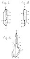
- the device comprises a flat body 1, for example made of plastic, metal, glass or similar material.
- a first capillary space 2 is formed inside the body and has an inlet aperture 2 ⁇ .
- Said capillary space 2 has a cross section which is in the form of a rectangle with a longitudinal measurement of, for example, 5 mm and a transverse measurement of, for example, 0.7 mm, the length of the space being approximately 20 mm.
- the body 1 also contains a second capillary space 3 with an outlet aperture 3 ⁇ .
- the space 3 is, for example, 25 mm in length and is square in cross section with, for example, measurements of 0.7 by 0.7 mm. Said space 3 gradually merges with the space 2 via the slanting walls 4.
- the inlet aperture 2 ⁇ When the device is in use the inlet aperture 2 ⁇ is dipped in a quantity of blood which is obtained, for example, through an incision in the skin, this inlet aperature 2 ⁇ being pointed downwards. A quantity of the blood is then sucked up into the capillary space 2. So long as the inlet aperture is in contact with the blood, blood will flow in until a state of equilibrium has been reached between gravity and the capillary forces. The body 1 is then turned over to the position shown in Figure 1, so that the quantity of blood in the space 2 flows downwards into the capillary space 3 and in drop form out of the outflow aperture 3 ⁇ , until a state of equilibrium has come about again between gravity and the capillary forces. The quantity of blood sucked up into the space 2 is greater here than the quantity of blood with which the latter-mentioned state of equilibrium is reached, so that at least one drop of blood comes out of the outflow aperature 3 ⁇ .
- a collection container not shown, connected to the outlet aperture 3 ⁇ , can be connected detachably, preferably in tear-off form, to the body 1. When it is full of blood dripping out of the outlet aperature 3 ⁇ , this container can then be torn off the body 1, so that an accurate quantity of blood corresponding to the capacity of the container is obtained, which can be smaller than one drop.
- the embodiment shown in figure 2 comprises substantially one half of the device shown in figure 1 so that of the first and second capillary spaces 5 and 6 respectively the one sides 5 ⁇ and 6 ⁇ are open and the inlet and outlet apertures 5 ⁇ and 6 ⁇ respectively are bounded by only three sides of a rectangle and a square respectively, whereas one 7 ⁇ of the slanting walls 7 is also cut open.
- the first capillary space 8 has a laterally protruding portion 8 ⁇ spaced apart from the inlet orifice 8 ⁇ and from the slanting walls 9 via which said first capillary space 8 merges with the second capillary space 10 having outlet orifice 10 ⁇ .
- a sharp metal cutting member 11 for making an incision in the skin of a living being is mounted in a recess formed in the portion adjacent to the first capillary space 8.
Abstract
Description
- The invention relates to a device for sucking up and releasing a liquid drop by drop.
- Such a device is used in particular for sucking up blood, for example obtained through an incision in the skin of a living being, and subsequently obtaining one or more drops of this blood for carrying out a test or tests, for example for determining the composition of the blood.
- A known device of this type consists of a pipette with a balloon connected thereto. When the balloon is squeezed by hand and then gradually released, while the rather pointed end of the pipette is dipped in the blood, a quantity of blood can be sucked up into the pipette, after which one or more drops of blood can be expelled from the pipette by squeezing the balloon again.
- The disadvantage of this device is that the size of the drops obtained depends on the force with which the balloon is squeezed, so that it is practically impossible to obtain drops of constant size, which is generally a requirement for carrying out the tests. Besides, it is already difficult per se to expel a single drop of blood from the pipette every time with the known device.
- Further EP-A-0002038 discloses a capillary vessel comprising a vessel and a member having a funnel-shaped portion which forms the capillar which member is detachably connected to said vessel. When the capillar is dipped in a quantity of blood said blood will be sucked up by the capillary force but soon afterwards will flow by gravity into the vessel without being impeded by the capillary force.
- The object of the invention is to produce a device of the known type which does not have these disadvantages.
- This object is achieved in that the device according to the invention comprises a first capillary space with at least one inlet aperture, said space being connected to at least a second smaller capillary space having at least one outlet aperture, while the first capillary space is formed in such a way that when the inlet aperture is dipped in the liquid in question a certain minimum quantity of the liquid can be sucked up into said space, and the second capillary space is formed in such a way that when the device is placed with the outlet aperture pointing downwards a quantity of the liquid in question can be retained in said second space through the capillary forces, the later quantity being smaller than the first-mentioned minimum quantity, while the outlet aperture is designed in such a way that the quantity of liquid which is the difference between the first and second quantity can flow out of the second capillary space essentially in drop form.
- With a device in this way capillary forces are thus used exclusively both for sucking up a quantity of blood and for obtaining one or more drops of blood for taking samples, so that during the formation of the drops no mechanical forces and/or shape changes occur, with the result that the size of the drops is not affected by other factors and is therefore highly constant. Moreover, air bubbles do not occur, which helps to keep the drop size constant.
- The first capillary space is preferably elongated in cross section, with a longer longitudinal elongated and a shorter transverse measurement at right angles thereto, while at least the part of the second capillary space adjoining the outflow aperture is of a cross-sectional shape which has essentially equal longitudinal and transverse measurements virtually of the same order of size as the transverse measurement of the first capillary space.
- In an embodiment which is simple to produce the first capillary space is rectangular in transverse section and the above-mentioned part of the second capillary space is in the form of a square in cross section, the capillary space which is elongated in cross section preferably merging gradually into the above-mentioned part of the second capillary space.
- A collection container can be advantageously connected to the outlet aperture, said container being detachably connected to the device.
- When a quantity of blood has been sucked into the device, said container can be filled with the blood flowing in drops from the outflow aperture and can then be removed from the device, so that a quantity of blood corresponding exactly to the capacity of the container is obtained.
- The invention will now be explained in greater detail with reference to the drawing, in which the embodiments of the device according to the invention are illustrated.
- As shown in figure 1, the device comprises a
flat body 1, for example made of plastic, metal, glass or similar material. - A first
capillary space 2 is formed inside the body and has an inlet aperture 2ʹ. Saidcapillary space 2 has a cross section which is in the form of a rectangle with a longitudinal measurement of, for example, 5 mm and a transverse measurement of, for example, 0.7 mm, the length of the space being approximately 20 mm. - The
body 1 also contains a secondcapillary space 3 with an outlet aperture 3ʹ. Thespace 3 is, for example, 25 mm in length and is square in cross section with, for example, measurements of 0.7 by 0.7 mm. Saidspace 3 gradually merges with thespace 2 via theslanting walls 4. - When the device is in use the inlet aperture 2ʹ is dipped in a quantity of blood which is obtained, for example, through an incision in the skin, this inlet aperature 2ʹ being pointed downwards. A quantity of the blood is then sucked up into the
capillary space 2. So long as the inlet aperture is in contact with the blood, blood will flow in until a state of equilibrium has been reached between gravity and the capillary forces. Thebody 1 is then turned over to the position shown in Figure 1, so that the quantity of blood in thespace 2 flows downwards into thecapillary space 3 and in drop form out of the outflow aperture 3ʹ, until a state of equilibrium has come about again between gravity and the capillary forces. The quantity of blood sucked up into thespace 2 is greater here than the quantity of blood with which the latter-mentioned state of equilibrium is reached, so that at least one drop of blood comes out of the outflow aperature 3ʹ. - A collection container, not shown, connected to the outlet aperture 3ʹ, can be connected detachably, preferably in tear-off form, to the
body 1. When it is full of blood dripping out of the outlet aperature 3ʹ, this container can then be torn off thebody 1, so that an accurate quantity of blood corresponding to the capacity of the container is obtained, which can be smaller than one drop. - The embodiment shown in figure 2 comprises substantially one half of the device shown in figure 1 so that of the first and second
capillary spaces slanting walls 7 is also cut open. - In the embodiment shown in figure 3 the first
capillary space 8 has a laterally protruding portion 8ʺ spaced apart from the inlet orifice 8ʹ and from theslanting walls 9 via which said firstcapillary space 8 merges with the secondcapillary space 10 having outlet orifice 10ʹ. A sharp metal cutting member 11 for making an incision in the skin of a living being is mounted in a recess formed in the portion adjacent to the firstcapillary space 8.
Claims (6)
- Device for sucking up and releasing a liquid drop by drop, the device comprising a first capillary space (2) with at least one inlet aperture, (2') characterized in that said space being connected to at least a second smaller capillary space (3) having at least one outlet aperture (3'), while the first capillary space being formed in such a way that when the inlet aperture (2') is dipped in the liquid in question a certain minimum quantity of the liquid can be sucked up into said space, and the second capillary space (3) is formed in such a way that when the device is placed with the outlet aperture (3') pointing downwards a quantity of the liquid in question can be retained in said second space (3) through capillary forces, the latter quantity being smaller than the first-mentioned minimum quantity, while the outlet aperture (3') is designed in such a way that the quantity of liquid which is the difference between the first and second quantity can flow out of the second capillary space (3) essentially in drop form.
- Device according to claim 1, characterized in that the first capillary space is elongated in cross section, with a longer longitudinal measurement and a shorter transverse measurement at right angles thereto, while at least the part of the second capillary space adjoining the outflow aperture is of a cross sectional shape which has essentially equal longitudinal and transverse measurements virtually of the same orer of size as the transverse measurement of the first capillary space.
- Device according to claim 2, characterized in that at least one of said capillary spaces is open at one of its short sides corresponding with said shorter transverse measurement.
- Device according to claim 2, characterized in that the first capillary space has a cross section which is in the form of a rectangle, and the above-mentioned part of the second capillary space has a cross section which is in the form of a square.
- Device according to claims 2-4, characterized in that the capillary space with elongated cross section gradually merges into the above-mentioned part of the second capillary space.
- Device according to claims 1-5, characterized in that a collection container is connected to the outlet aperture and is detachably connected to the device.
Priority Applications (1)
| Application Number | Priority Date | Filing Date | Title |
|---|---|---|---|
| AT88200158T ATE87450T1 (en) | 1987-02-05 | 1988-01-29 | DEVICE FOR SUCTIONING AND DISPENSING DROPPLY A LIQUID. |
Applications Claiming Priority (2)
| Application Number | Priority Date | Filing Date | Title |
|---|---|---|---|
| NL8700277A NL8700277A (en) | 1987-02-05 | 1987-02-05 | DEVICE FOR VACUUM AND DROPPING A LIQUID. |
| NL8700277 | 1987-02-05 |
Publications (2)
| Publication Number | Publication Date |
|---|---|
| EP0280347A1 EP0280347A1 (en) | 1988-08-31 |
| EP0280347B1 true EP0280347B1 (en) | 1993-03-31 |
Family
ID=19849522
Family Applications (1)
| Application Number | Title | Priority Date | Filing Date |
|---|---|---|---|
| EP88200158A Expired - Lifetime EP0280347B1 (en) | 1987-02-05 | 1988-01-29 | Device for sucking up and releasing a liquid drop by drop |
Country Status (9)
| Country | Link |
|---|---|
| EP (1) | EP0280347B1 (en) |
| JP (1) | JPS6485634A (en) |
| CN (1) | CN88100416A (en) |
| AT (1) | ATE87450T1 (en) |
| DE (1) | DE3879731T2 (en) |
| DK (1) | DK165963C (en) |
| NL (1) | NL8700277A (en) |
| NO (1) | NO880501L (en) |
| RU (1) | RU1769726C (en) |
Families Citing this family (11)
| Publication number | Priority date | Publication date | Assignee | Title |
|---|---|---|---|---|
| JP3621617B2 (en) * | 2000-01-21 | 2005-02-16 | ブラザー工業株式会社 | Capillary device for measuring glucose concentration, noninvasive monitoring method of glucose concentration, and noninvasive monitoring method of blood glucose level |
| US20030039587A1 (en) * | 2001-08-22 | 2003-02-27 | Volker Niermann | Transfer device |
| AU2003297853A1 (en) * | 2002-12-24 | 2004-07-29 | F. Hoffmann-La Roche Ag | A sampling device utilizing biased capillary action |
| JP2007504438A (en) * | 2003-09-01 | 2007-03-01 | インバーネス・メデイカル・スウイツツアーランド・ゲゼルシヤフト・ミツト・ベシユレンクテル・ハフツング | Sampling device using capillary action |
| US7955271B2 (en) | 2006-10-13 | 2011-06-07 | Roche Diagnostics Operations, Inc. | Tape transport lance sampler |
| US8852124B2 (en) | 2006-10-13 | 2014-10-07 | Roche Diagnostics Operations, Inc. | Tape transport lance sampler |
| US7677695B2 (en) | 2007-08-13 | 2010-03-16 | Hewlett-Packard Development Company, L.P. | Fluid transfer device including a die |
| US8658110B2 (en) | 2007-08-13 | 2014-02-25 | Hewlett-Packard Development Company, L.P. | Fluid delivery system |
| JP5507991B2 (en) * | 2009-12-15 | 2014-05-28 | 日本電信電話株式会社 | applicator |
| JP5483616B2 (en) * | 2011-06-15 | 2014-05-07 | 日本電信電話株式会社 | Flow cell and flow cell feeding method |
| CN109416303A (en) * | 2016-07-06 | 2019-03-01 | 尼普洛株式会社 | Sample collects tip, sample prepares container and sample preparation external member |
Family Cites Families (3)
| Publication number | Priority date | Publication date | Assignee | Title |
|---|---|---|---|---|
| FR1442456A (en) * | 1965-04-28 | 1966-06-17 | Drip tip | |
| US4003262A (en) * | 1974-12-16 | 1977-01-18 | Becton, Dickinson And Company | Apparatus for measuring precise micro quantities of fluid samples |
| DE2751503C2 (en) * | 1977-11-18 | 1983-03-24 | Walter Sarstedt Kunststoff-Spritzgußwerk, 5223 Nümbrecht | Blood collection vessel |
-
1987
- 1987-02-05 NL NL8700277A patent/NL8700277A/en not_active Application Discontinuation
-
1988
- 1988-01-29 DE DE88200158T patent/DE3879731T2/en not_active Expired - Fee Related
- 1988-01-29 AT AT88200158T patent/ATE87450T1/en not_active IP Right Cessation
- 1988-01-29 EP EP88200158A patent/EP0280347B1/en not_active Expired - Lifetime
- 1988-02-04 NO NO880501A patent/NO880501L/en unknown
- 1988-02-04 DK DK057588A patent/DK165963C/en not_active IP Right Cessation
- 1988-02-04 CN CN198888100416A patent/CN88100416A/en active Pending
- 1988-02-04 RU SU884355180A patent/RU1769726C/en active
- 1988-02-05 JP JP63026407A patent/JPS6485634A/en active Pending
Also Published As
| Publication number | Publication date |
|---|---|
| NL8700277A (en) | 1988-09-01 |
| EP0280347A1 (en) | 1988-08-31 |
| DE3879731D1 (en) | 1993-05-06 |
| CN88100416A (en) | 1988-08-17 |
| DE3879731T2 (en) | 1993-10-14 |
| JPS6485634A (en) | 1989-03-30 |
| DK57588A (en) | 1988-08-06 |
| DK165963B (en) | 1993-02-22 |
| NO880501L (en) | 1988-08-08 |
| RU1769726C (en) | 1992-10-15 |
| NO880501D0 (en) | 1988-02-04 |
| ATE87450T1 (en) | 1993-04-15 |
| DK165963C (en) | 1993-07-05 |
| DK57588D0 (en) | 1988-02-04 |
Similar Documents
| Publication | Publication Date | Title |
|---|---|---|
| EP0280347B1 (en) | Device for sucking up and releasing a liquid drop by drop | |
| US4589421A (en) | Sampling device | |
| US5460782A (en) | Automatic filling micropipette with dispensing means | |
| US5238649A (en) | Specimen test unit | |
| US4563104A (en) | Liquid dispensing pipette and stirrer device | |
| US6401552B1 (en) | Centrifuge tube and method for collecting and dispensing mixed concentrated fluid samples | |
| US5266266A (en) | Specimen test unit | |
| US4707450A (en) | Specimen collection and test unit | |
| US9656258B2 (en) | Pipette | |
| FI60315C (en) | KAPILLAERVISKOSIMETER | |
| US4917274A (en) | Miniscule droplet dispenser tip | |
| EP0209705B1 (en) | A disposable preselected-volume capillary pipet device and method of preparing a liquid sample for testing | |
| US20110124984A1 (en) | Device for Aliquoting and Filtering Blood | |
| US3952599A (en) | Fractional-fill capillary pipette and method | |
| US3518804A (en) | Pipette assembly having precise quantity stabilized reagent in liquid form and method of preparing same | |
| JP2536946B2 (en) | Liquid control nozzle structure for liquid distribution | |
| US4003262A (en) | Apparatus for measuring precise micro quantities of fluid samples | |
| ES2755329T3 (en) | Test and sample preparation system | |
| JPS62133936A (en) | Apparatus for sampling minute amount of blood | |
| US2974528A (en) | Pipette | |
| CN108627636B (en) | Device and method for detecting liquid solidification | |
| US5125278A (en) | Volumetric pipette | |
| EP0490447A1 (en) | A disposable liquid testing device | |
| FI891379A (en) | Apparatus for dispensing a liquid sample into a diagnostic device at a controlled rate | |
| CN101430337A (en) | Liquid dispensing tip with reservoir |
Legal Events
| Date | Code | Title | Description |
|---|---|---|---|
| PUAI | Public reference made under article 153(3) epc to a published international application that has entered the european phase |
Free format text: ORIGINAL CODE: 0009012 |
|
| AK | Designated contracting states |
Kind code of ref document: A1 Designated state(s): AT BE CH DE ES FR GB GR IT LI LU NL SE |
|
| 17P | Request for examination filed |
Effective date: 19890215 |
|
| 17Q | First examination report despatched |
Effective date: 19920708 |
|
| GRAA | (expected) grant |
Free format text: ORIGINAL CODE: 0009210 |
|
| AK | Designated contracting states |
Kind code of ref document: B1 Designated state(s): AT BE CH DE ES FR GB GR IT LI LU NL SE |
|
| PG25 | Lapsed in a contracting state [announced via postgrant information from national office to epo] |
Ref country code: IT Free format text: LAPSE BECAUSE OF FAILURE TO SUBMIT A TRANSLATION OF THE DESCRIPTION OR TO PAY THE FEE WITHIN THE PRE;WARNING: LAPSES OF ITALIAN PATENTS WITH EFFECTIVE DATE BEFORE 2007 MAY HAVE OCCURRED AT ANY TIME BEFORE 2007. THE CORRECT EFFECTIVE DATE MAY BE DIFFERENT FROM THE ONE RECORDED.SCRIBED TIME-LIMIT Effective date: 19930331 Ref country code: GR Free format text: LAPSE BECAUSE OF FAILURE TO SUBMIT A TRANSLATION OF THE DESCRIPTION OR TO PAY THE FEE WITHIN THE PRESCRIBED TIME-LIMIT Effective date: 19930331 Ref country code: LI Effective date: 19930331 Ref country code: AT Effective date: 19930331 Ref country code: ES Free format text: THE PATENT HAS BEEN ANNULLED BY A DECISION OF A NATIONAL AUTHORITY Effective date: 19930331 Ref country code: SE Effective date: 19930331 Ref country code: CH Effective date: 19930331 |
|
| REF | Corresponds to: |
Ref document number: 87450 Country of ref document: AT Date of ref document: 19930415 Kind code of ref document: T |
|
| REF | Corresponds to: |
Ref document number: 3879731 Country of ref document: DE Date of ref document: 19930506 |
|
| REG | Reference to a national code |
Ref country code: CH Ref legal event code: PL |
|
| ET | Fr: translation filed | ||
| PG25 | Lapsed in a contracting state [announced via postgrant information from national office to epo] |
Ref country code: GB Effective date: 19940129 |
|
| PG25 | Lapsed in a contracting state [announced via postgrant information from national office to epo] |
Ref country code: LU Free format text: LAPSE BECAUSE OF NON-PAYMENT OF DUE FEES Effective date: 19940131 |
|
| PLBE | No opposition filed within time limit |
Free format text: ORIGINAL CODE: 0009261 |
|
| STAA | Information on the status of an ep patent application or granted ep patent |
Free format text: STATUS: NO OPPOSITION FILED WITHIN TIME LIMIT |
|
| 26N | No opposition filed | ||
| GBPC | Gb: european patent ceased through non-payment of renewal fee |
Effective date: 19940129 |
|
| PG25 | Lapsed in a contracting state [announced via postgrant information from national office to epo] |
Ref country code: FR Effective date: 19940930 |
|
| REG | Reference to a national code |
Ref country code: FR Ref legal event code: ST |
|
| PGFP | Annual fee paid to national office [announced via postgrant information from national office to epo] |
Ref country code: NL Payment date: 19960531 Year of fee payment: 9 |
|
| PGFP | Annual fee paid to national office [announced via postgrant information from national office to epo] |
Ref country code: DE Payment date: 19960703 Year of fee payment: 9 |
|
| PGFP | Annual fee paid to national office [announced via postgrant information from national office to epo] |
Ref country code: BE Payment date: 19960705 Year of fee payment: 9 |
|
| PG25 | Lapsed in a contracting state [announced via postgrant information from national office to epo] |
Ref country code: BE Effective date: 19970131 |
|
| BERE | Be: lapsed |
Owner name: MICROPLAST B.V. Effective date: 19970131 Owner name: LIVESTOCK CONTROL HOLDING B.V. Effective date: 19970131 |
|
| PG25 | Lapsed in a contracting state [announced via postgrant information from national office to epo] |
Ref country code: NL Effective date: 19970801 |
|
| NLV4 | Nl: lapsed or anulled due to non-payment of the annual fee |
Effective date: 19970801 |
|
| PG25 | Lapsed in a contracting state [announced via postgrant information from national office to epo] |
Ref country code: DE Effective date: 19971001 |