EP0280149B1 - Scheibenwischer - Google Patents
Scheibenwischer Download PDFInfo
- Publication number
- EP0280149B1 EP0280149B1 EP88102197A EP88102197A EP0280149B1 EP 0280149 B1 EP0280149 B1 EP 0280149B1 EP 88102197 A EP88102197 A EP 88102197A EP 88102197 A EP88102197 A EP 88102197A EP 0280149 B1 EP0280149 B1 EP 0280149B1
- Authority
- EP
- European Patent Office
- Prior art keywords
- windshield
- wiper
- streamlined structure
- fact
- blade
- Prior art date
- Legal status (The legal status is an assumption and is not a legal conclusion. Google has not performed a legal analysis and makes no representation as to the accuracy of the status listed.)
- Expired
Links
- 239000011435 rock Substances 0.000 claims description 5
- 238000006073 displacement reaction Methods 0.000 description 2
- 239000000463 material Substances 0.000 description 2
- 239000004033 plastic Substances 0.000 description 2
- 230000001105 regulatory effect Effects 0.000 description 2
- 229910000639 Spring steel Inorganic materials 0.000 description 1
- 230000006835 compression Effects 0.000 description 1
- 238000007906 compression Methods 0.000 description 1
- 230000001276 controlling effect Effects 0.000 description 1
- 230000001419 dependent effect Effects 0.000 description 1
- 238000011161 development Methods 0.000 description 1
- 230000018109 developmental process Effects 0.000 description 1
- 230000000694 effects Effects 0.000 description 1
- 239000013536 elastomeric material Substances 0.000 description 1
- 238000009434 installation Methods 0.000 description 1
- 238000004519 manufacturing process Methods 0.000 description 1
- 239000002184 metal Substances 0.000 description 1
Images
Classifications
-
- B—PERFORMING OPERATIONS; TRANSPORTING
- B60—VEHICLES IN GENERAL
- B60S—SERVICING, CLEANING, REPAIRING, SUPPORTING, LIFTING, OR MANOEUVRING OF VEHICLES, NOT OTHERWISE PROVIDED FOR
- B60S1/00—Cleaning of vehicles
- B60S1/02—Cleaning windscreens, windows or optical devices
- B60S1/04—Wipers or the like, e.g. scrapers
- B60S1/32—Wipers or the like, e.g. scrapers characterised by constructional features of wiper blade arms or blades
- B60S1/38—Wiper blades
- B60S1/3801—Wiper blades characterised by a blade support harness consisting of several articulated elements
-
- B—PERFORMING OPERATIONS; TRANSPORTING
- B60—VEHICLES IN GENERAL
- B60S—SERVICING, CLEANING, REPAIRING, SUPPORTING, LIFTING, OR MANOEUVRING OF VEHICLES, NOT OTHERWISE PROVIDED FOR
- B60S1/00—Cleaning of vehicles
- B60S1/02—Cleaning windscreens, windows or optical devices
- B60S1/04—Wipers or the like, e.g. scrapers
- B60S1/32—Wipers or the like, e.g. scrapers characterised by constructional features of wiper blade arms or blades
- B60S1/38—Wiper blades
- B60S1/3806—Means, or measures taken, for influencing the aerodynamic quality of the wiper blades
-
- B—PERFORMING OPERATIONS; TRANSPORTING
- B60—VEHICLES IN GENERAL
- B60S—SERVICING, CLEANING, REPAIRING, SUPPORTING, LIFTING, OR MANOEUVRING OF VEHICLES, NOT OTHERWISE PROVIDED FOR
- B60S1/00—Cleaning of vehicles
- B60S1/02—Cleaning windscreens, windows or optical devices
- B60S1/04—Wipers or the like, e.g. scrapers
- B60S1/32—Wipers or the like, e.g. scrapers characterised by constructional features of wiper blade arms or blades
- B60S1/40—Connections between blades and arms
-
- B—PERFORMING OPERATIONS; TRANSPORTING
- B60—VEHICLES IN GENERAL
- B60S—SERVICING, CLEANING, REPAIRING, SUPPORTING, LIFTING, OR MANOEUVRING OF VEHICLES, NOT OTHERWISE PROVIDED FOR
- B60S1/00—Cleaning of vehicles
- B60S1/02—Cleaning windscreens, windows or optical devices
- B60S1/04—Wipers or the like, e.g. scrapers
- B60S1/32—Wipers or the like, e.g. scrapers characterised by constructional features of wiper blade arms or blades
- B60S1/38—Wiper blades
- B60S2001/3812—Means of supporting or holding the squeegee or blade rubber
Definitions
- the present invention relates to a perfected windshield wiper suitable for fitment to vehicles and, in particular, designed to ensure optimum wiping of the windshield under all atmospheric conditions and at any vehicle speed, even in the presence of a single wiper blade.
- the wiping efficiency of a windshield wiper is known to depend on the pressure exerted by the wiper blade on the glazing surface of the windshield as the blade swings back and forth.
- the wiper blade formed from flexible material such as rubber, is carried on a complex blade carrier member which, in turn, is carried via an articulated joint on a rigid arm connected, in radially-projecting manner and by means of a further articulated device, to a cap-shaped connecting element mounted angularly rigid with a control pin. Reciprocal rotation of the said pin, which is controlled by a motor, activates the wiper by swinging the arm and respective blade through a given arc.
- the complex, cumbersome assembly consisting of the blade carrier member, articulated joint and arm, creates numerous streamlining problems, which may result in noise, an increase in the drag coefficient of the vehicle, and worse still, partial or total detachment of the wiper blade from the windshield, thus reducing or removing all contact pressure between the blade and windshield, and, consequently, impairing both wiping performance and visibility.
- the aim of the present invention is to provide a windshield wiper designed to overcome the aforementioned drawbacks, i.e. a wiper of straightforward, compact design, that is easy and cheap to manufacture, and provides for both optimum wiping performance and streamlining.
- a windshield wiper as defined in Claim 1.
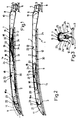
- Number 1 in Fig.s 2 and 3 indicates a windshield wiper, in particular, a single-blade wiper, for wiping the outer surface 2 of a windshield 3 of any curvature, or the glazing surface of a backlight or headlight on a known vehicle (not shown), e.g. an automobile.
- Wiper 1 comprising a known cap-shaped connecting element 4 designed to fit angularly integral with a rotary pin 5 controlling wiper 1, supported on body 6 of the said vehicle (not shown), and powered by a known motor (not shown); an arm 7 carried in radially-projecting manner on the said connecting element 4 and connected angularly integral with the same by means of an articulated device 8; and a flexible wiper blade 9 formed in one piece from elastomeric material, e.g. rubber, and mounted integral with arm 7. Blade 9 is of known type, and formed so as to cooperated in sliding manner with, and wipe, the said surface 2 by moving over the same at a given pressure.
- Such pressure is provided by arm 7, partly by means of articulated joint 8, which may be provided in known manner with a spring (not shown) and is designed to enable rotation of end 10 of arm 7, adjacent to connecting element 4, about an axis perpendicular to the axis of rotation of pin 5 and substantially parallel with the plane of windshield 3, and partly, according to the present invention, by virtue of the special design of arm 7 itself.
- articulated device 8 which is a commonly known type, substantially identical to those employed on known windshield wipers currently available on the market.
- blade 9 is carried directly on arm 7, which consists of a rigid, streamlined structure of such a length as to fully accommodate blade 9, and terminating, at the connecting element 4 end, in end 10 incorporated inside articulated joint 8, and, at the opposite end, in a longitudinally-tapered cap 11 defining the end of structure 7 opposite the said end 10.
- Streamlined structure or arm 7 may be formed from bent sheet metal, or molded from synthetic plastic, and is shaped longitudinally so as to substantially match the mean curvature of surface 2.
- structure 7 is also curved and presents, at each longitudinal point, a concentric radius of curvature slightly greater than that of surface 2.
- the cross section of structure 7, is substantially constant, and substantially in the form of an inverted U with its open end facing downwards in the direction of windshield 3.
- Blade 9 is housed longitudinally over its entire length inside structure or arm 7, and is arranged in line with structure 7 in an open bottom portion 12 of the same, with its bottom longitudinal wiping edge 14 projecting downwards beyond portion 12 and in the direction of windshield 3.
- the top longitudinal edge 15 of flexible blade 9, opposite the said edge 14 and preferably having a T-shaped section, is connected with structure or arm 7 so as to form a single unit therewith via elastic means 18 housed inside structure 7, between a bottom wall 19 of the same and blade 9.
- the said elastic means are defined by a number of flexible V-shaped bows 18 arranged side by side, preferably singly, in a row along the entire length of structure 7, with their respective opposite ends 20 arranged adjacent to one another and secured integral with edge 15, and with a respective center line portion 21, at the tip of the V defined by each bow 18, hinged to structure 7 in such a manner as to enable bows 18 to rock about respective axes parallel with each other and with the rotation axis of articulated device 8, and all lying crosswise in relation to the longitudinal axis of structure or arm 7.
- each of the said bows 18 present, on the said center line portion 21, respective opposed transverse projecting pins 22 engaged in idle manner inside respective pairs of coaxial transverse holes 23 formed through respective side walls 24 of structure 7.
- each of the said bows 18 consists of a single flexible element formed from plastic or spring steel and shaped in the form of an inverted V, the center line portion 21 of which is substantially omega-shaped with integral laterally-projecting pins 22, which click inside lateral holes or seats 23, crosswise in relation to the axis of structure 7.
- Cap 11 is defined outwards by a curved surface, and is connected in rocking manner to the rest of structure 7 by pivoting on pins 22 of adjacent bow 18 which, numbered 18a in Fig.2, may be asymmetrical in relation to portion 21, depending on the length of cap 11. Cap 11 is thus free to rock, together with element 18a, in relation to the rest of structure 7, so as to adapt its position to the local curvature of windshield 3.
- bows 18 are formed from materials having different elastic properties, or in slightly different shapes or sections, so as to present varying grades of rigidity.
- Flexible blade 9 is thus secured to rigid structure 7 by restraints differing in rigidity at various points on the structure and consequently also on windscreen 3, so as to produce a flexible connection varying in rigidity at various points between blade 9 and arm 7, and designed to resist, with given force, any displacement of blade 9 inwards of structure 7 (which results in compression and consequent springback of bows 18), while at the same time permitting varying longitudinal flexure of blade 9 at various points along the same, for enabling the blade contour to adapt continuously to the curvature of surface 2, even in the presence of continuous random variations in the same.
- the cross-section of the streamlined structure defining arm 7 presents opposite longitundinal edges 30 tapering outwards in thickness, curving away from each other, and located a given, relatively small distance from edge 14, so as to skim surface 2.
- arm 7, in the idle position against one side of windshield 3, maintains the required contact pressure between edge 14 and surface 2 by virtue of the known performance of articulated joint 8. Reciprocal rotation of pin 5 causes arm 7 to move parallel with windshield 3, thus causing edge 14 to slide over and to wipe surface 2.
- rocking bows 18 enable flexible blade 9 to adapt to any variations in the curvature of windshield 3 by allowing it to make differential adjustment to its own curvature at various points along its length, thus maintaining, at each point on surface 2, the correct contact pressure imposed by articulated joint 8 between surface 2 and edge 14, and ensuring optimum wiping of windshield 3.
- Streamlining of arm 7 and installation of blade 9 inside the same reduce or eliminate aerodynamic disturbance, thus preventing noise or whistling at high vehicle speeds.
- the shape of edges 30 provides for effective downflow for maintaining blade grip on the windshield and preventing lift-off of the blade under all driving conditions.
- streamlined structure 7 also provides for effective removal of large quantities of packed snow off windshield 3.
- Fig.1 shows a windshield wiper 1a identical to wiper 1 except for the design of bows 18.
- Each of bows 18 on windshield wiper 1a consists of a pair of oblique arms 32 having a first end 33 secured integral with blade 9 and a second opposite end 34 pivoting on a common pin 22 fitted crosswise inside structure 7; and a spring 35 designed to force arms 32 towards each other by rotating respective ends 34 pivoting on pin 22.
- the rigidity of bow 18 as a whole may be regulated to produce the same effect already described in connection with windshield wiper 1.
- Operation of wiper 1a is also identical to that of wiper 1.
- the advantages of the present invention will be clear from the foregoing description.
- the windshield wiper according to the present invention may, of course, be employed in conjunction with a second symmetrical wiper activated by a second control pin, thus enabling the advantages of the present invention to be extended also to two-blade windshield wipers.
Claims (9)
- Scheibenwischer (1, 1a), der ein aufsatzförmiges Verbindungselement (4), das einstückig im Winkel mit dem Drehstift (5) verbunden ist, der den Wischer steuert; einen Arm (7), der in radial vorstehender Weise auf dem Verbindungselement (4) gehalten wird und durch eine gegliederte Einrichtung (8) im Winkel starr mit diesem (4) verbunden ist; und ein flexibles Wischerblatt (9) umfaßt, das durch diesen Arm (7) gehalten wird und so gestaltet ist, daß es in gleitender Weise mit der Außenoberfläche der Windschutzscheibe (3) in Wechselwirkung steht; dadurch gekennzeichnet, daß der Arm aus einer hohlen, starren, stromlinienförmigen Struktur (7) besteht, die gekrümmt ist und an jedem Längspunkt einen konzentrischen Krümmungsradius zeigt, der etwas größer als der der Außenoberfläche (2) der Windschutzscheibe (3) ist, wobei diese Struktur einen im wesentlichen V-förmigen Querschnitt aufweist und das Wischerblatt (9) über seine gesamte Länge in Längsrichtung umgibt; wobei das Wischerblatt (9) im offenen unteren Abschnitt (12) der stromlinienförmigen Struktur angeordnet ist, wobei die längs verlaufende Wischerkante (14) nach unten aus dieser stromlinienförmigen Struktur in Richtung der Windschutzscheibe vorsteht; wobei der Scheibenwischer auch eine elastische Einrichtung (18, 18a) umfaßt, die innerhalb der stromlinienförmigen Struktur (7) enthalten ist und diese mit dem Wischerblatt (9) mechanisch verbindet, wobei die elastische Einrichtung das Wischerblatt (9) mit einer bestimmten Kraft aus der stromlinienförmigen Struktur (7) drückt und in einer solchen Weise gezwungen wird, daß das Wischerblatt an unterschiedlichen Punkten entlang des Blattes unterschiedliche Krümmungen annehmen kann.
- Scheibenwischer nach Anspruch 1, dadurch gekennzeichnet, daß die elastische Einrichtung eine Anzahl flexibler V-förmiger Bögen (18, 18a) umfaßt, die nebeneinander über die gesamte Länge der stromlinienförmigen Struktur (7) in einer Reihe angeordnet sind, wobei ihre entsprechenden entgegengesetzten Enden (20, 33) einander benachbart sind; wobei die Bögen (18, 18a) entlang der Mittellinie schwenkbar an diese stromlinienförmige Struktur (7) angebracht sind, so daß sie parallel zueinander um entsprechende Achsen schwenken, wobei alle im Verhaltnis zur Längsachse des Armes (7) kreuzweise angeordnet sind.
- Scheibenwischer nach Anspruch 2, dadurch gekennzeichnet, daß die gegliederte Einrichtung (8) so gestaltet ist, daß sich das Ende des Armes (7) neben dem Verbindungselement (4) um eine Achse, die zur Rotationsachse des Regelstiftes (5) senkrecht ist, und im wesentlichen parallel zur Ebene der Windschutzscheibe (3) drehen kann.
- Scheibenwischer nach Anspruch 3, dadurch gekennzeichnet, daß die entgegengesetzten Enden (20, 33) der Bögen (18, 18a) einstückig mit der Oberkante (15) des Wischerblattes (9) entgegengesetzt zur Wischerkante (14) dieses Blattes angebracht sind; und die Mittellinie der Bögen (18, 18a) mit der Spitze des V zusammenfällt, das durch jeden Bogen (18, 18a) definiert wird, und entsprechende entgegengesetzte Querstifte (22) aufweist, die in die entsprechenden Paare der koaxialen Löcher (23) eingreifen, die durch die entsprechenden Seitenwände (24) auf der stromlinienförmigen Struktur (7) gebildet werden, so daß sie um Achsen schwenken, die zur Rotationsachse der gegliederten Einrichtung (8) parallel sind.
- Scheibenwischer nach einem der vorstehenden Ansprüche 2 bis 4, dadurch gekennzeichnet, daß jeder der Bögen (18) aus einem Paar schräger Arme (32) mit einem ersten Ende (33), das einstückig mit dem Wischerblatt (9) verbunden ist, und einem zweiten entgegengesetzten Ende (34), das an einem gemeinsamen Punkt (22) schwenkbar an der stromlinienförmigen Struktur (7) hängt; und einer Feder (35) besteht, die so gestaltet ist, daß sie die beiden Arme (32) durch Rotation der entgegengesetzten Enden (34), die gemeinsam schwenken, gegeneinander drückt.
- Scheibenwischer nach einem der vorstehenden Ansprüche 2 bis 4, dadurch gekennzeichnet, daß jeder der Bögen (18) aus einem einzelnen flexiblen Element besteht, das im wesentlichen in Form eines umgekehrten V besteht, dessen Spitze auf dem Mittellinienabschnitt (21) des Elementes liegt; wobei der Mittellinienabschnitt (21) im wesentlichen Omega-förmig ist und ein Paar entgegengesetzter seitlich vorstehender Stifte (22) aufweist, die so gestaltet sind, daß sie in die entsprechenden seitlichen Aufnahmen (23), die durch die stromlinienförmige Struktur (7) gebildet werden, und im Verhältnis zu deren Achse kreuzweise einrasten.
- Scheibenwischer nach einem der vorstehenden Ansprüche, dadurch gekennzeichnet, daß die stromlinienförmige Struktur einen in Längsrichtung konischen Aufsatz (11) umfaßt, der das erste Ende der stromlinienförmigen Struktur (7) entgegengesetzt zum zweiten Ende dieser Struktur neben der gegliederten Einrichtung (8) definiert; wobei dieser Aufsatz (11) koaxial schwenkbar zur Schwenkachse des ersten (18a) der Bögen neben dem Aufsatz (11) an die Halterung der stromlinienförmigen Struktur (7) angebracht ist, so daß sie mit dieser schwingt.
- Scheibenwischer nach einem der vorstehenden Ansprüche, dadurch gekennzeichnet, daß der Querschnitt der stromlinienförmigen Struktur (7) entgegengesetzte Längskanten (30) zeigt, deren Dicke nach außen konisch verlauft, die voneinander weg gekrümmt und in einem vorgegebenen relativ geringen Abstand von der Wischerkante (14) des Blattes (9) angeordnet sind, um bei Verwendung über die Außenoberfläche (2) der Windschutzscheibe (3) zu streichen.
- Scheibenwischer nach einem der vorstehenden Ansprüche, dadurch gekennzeichnet, daß die Steifheit der elastischen Einrichtung (18) an verschiedenen Punkten auf dem Wischerblatt (9) variiert.
Applications Claiming Priority (2)
| Application Number | Priority Date | Filing Date | Title |
|---|---|---|---|
| IT8767145A IT1214382B (it) | 1987-02-27 | 1987-02-27 | Dispositivo tergicristallo di tipo perfezionato |
| IT6714587 | 1987-02-27 |
Publications (3)
| Publication Number | Publication Date |
|---|---|
| EP0280149A2 EP0280149A2 (de) | 1988-08-31 |
| EP0280149A3 EP0280149A3 (en) | 1989-06-07 |
| EP0280149B1 true EP0280149B1 (de) | 1992-10-07 |
Family
ID=11299961
Family Applications (1)
| Application Number | Title | Priority Date | Filing Date |
|---|---|---|---|
| EP88102197A Expired EP0280149B1 (de) | 1987-02-27 | 1988-02-15 | Scheibenwischer |
Country Status (4)
| Country | Link |
|---|---|
| EP (1) | EP0280149B1 (de) |
| DE (1) | DE3875132T2 (de) |
| ES (1) | ES2035117T3 (de) |
| IT (1) | IT1214382B (de) |
Cited By (1)
| Publication number | Priority date | Publication date | Assignee | Title |
|---|---|---|---|---|
| CN107000696A (zh) * | 2014-11-26 | 2017-08-01 | 罗伯特·博世有限公司 | 具有能够更换的刮水器橡胶的鳍条‑刮水器 |
Families Citing this family (12)
| Publication number | Priority date | Publication date | Assignee | Title |
|---|---|---|---|---|
| FR2650235B1 (fr) * | 1989-07-26 | 1991-10-04 | Valeo Systemes Dessuyage | Deflecteur d'air mobile pour balai d'essuie-glace, notamment de vehicules automobiles |
| FR2652324B1 (fr) * | 1989-09-22 | 1994-10-21 | Valeo Systemes Dessuyage | Deflecteur d'air a parties mobiles pour dispositif d'essuie-glace, notamment de vehicule automobile. |
| FR2653083A1 (en) * | 1989-10-13 | 1991-04-19 | Journee Paul Sa | Windscreen wiper equipped with a fairing device, particularly for a motor vehicle |
| FR2664217A1 (fr) * | 1990-07-05 | 1992-01-10 | Valeo Systemes Dessuyage | Balai d'essuie-glace carene. |
| FR2679186A1 (fr) * | 1991-07-16 | 1993-01-22 | Journee Paul Sa | Balai d'essuie-glace equipe d'un deflecteur aerodynamique. |
| FR2682340B1 (fr) * | 1991-10-14 | 1993-12-03 | Valeo Systemes Essuyage | Essuie-glace carene, notamment pour vehicule automobile. |
| FR2695606B1 (fr) * | 1992-09-14 | 1994-10-14 | Journee Paul Sa | Raclette d'essuyage pour un balai d'essuie-glace comportant une rampe d'alimentation et d'aspersion en liquide de lavage. |
| FR2704193B1 (fr) * | 1993-04-22 | 1995-06-02 | Journee Paul Sa | Essuie-glace de véhicule automobile. |
| DE19949887A1 (de) * | 1999-10-15 | 2001-04-19 | Volkswagen Ag | Wischerarm |
| KR100782794B1 (ko) | 2006-12-29 | 2007-12-05 | 박세헌 | 암과 블레이드 일체형 와이퍼 시스템 |
| DE102014226365A1 (de) * | 2014-12-18 | 2016-06-23 | Robert Bosch Gmbh | Scheibenwischvorrichtung |
| WO2019053481A1 (en) | 2017-09-14 | 2019-03-21 | Volvo Truck Corporation | WINDSCREEN WIPER, MOTOR VEHICLE COMPRISING SUCH A WIPER, AND METHOD FOR OPERATING SUCH A WIPER |
Family Cites Families (3)
| Publication number | Priority date | Publication date | Assignee | Title |
|---|---|---|---|---|
| FR2526382A1 (fr) * | 1982-05-05 | 1983-11-10 | Citroen Sa | Balai d'essuie-glace |
| FR2563481B3 (fr) * | 1984-04-11 | 1986-08-22 | Champion Spark Plug Europ | Systeme d'essuie-glace pour vehicules a moteur |
| DE8522252U1 (de) * | 1985-08-02 | 1986-11-27 | Robert Bosch Gmbh, 7000 Stuttgart, De |
-
1987
- 1987-02-27 IT IT8767145A patent/IT1214382B/it active
-
1988
- 1988-02-15 ES ES198888102197T patent/ES2035117T3/es not_active Expired - Lifetime
- 1988-02-15 EP EP88102197A patent/EP0280149B1/de not_active Expired
- 1988-02-15 DE DE8888102197T patent/DE3875132T2/de not_active Expired - Fee Related
Cited By (1)
| Publication number | Priority date | Publication date | Assignee | Title |
|---|---|---|---|---|
| CN107000696A (zh) * | 2014-11-26 | 2017-08-01 | 罗伯特·博世有限公司 | 具有能够更换的刮水器橡胶的鳍条‑刮水器 |
Also Published As
| Publication number | Publication date |
|---|---|
| DE3875132D1 (de) | 1992-11-12 |
| EP0280149A3 (en) | 1989-06-07 |
| EP0280149A2 (de) | 1988-08-31 |
| ES2035117T3 (es) | 1993-04-16 |
| DE3875132T2 (de) | 1993-02-25 |
| IT8767145A0 (it) | 1987-02-27 |
| IT1214382B (it) | 1990-01-18 |
Similar Documents
| Publication | Publication Date | Title |
|---|---|---|
| EP0280149B1 (de) | Scheibenwischer | |
| US5218735A (en) | Windshield wiper with main and auxiliary air deflector | |
| US5463790A (en) | Windshield wiper with an automatic pressure means | |
| US7228588B2 (en) | Wiper blade for cleaning panes, in particular of a motor vehicle | |
| KR100587729B1 (ko) | 자동차 유리용 와이퍼 블레이드 | |
| US8024836B2 (en) | Beam blade windshield wiper assembly having an airfoil | |
| US6675433B1 (en) | Beam blade wiper assembly having improved wind lift characteristics | |
| ES2383207T3 (es) | Hoja de goma limpiaparabrisas | |
| KR101723370B1 (ko) | 윈드스크린용 와이퍼장치 | |
| KR20040012794A (ko) | 유리창용 와이퍼장치 | |
| JPH0361151A (ja) | 自動車の窓拭きワイパー用可動気流偏向器 | |
| US20030074763A1 (en) | Wiper device for cleaning the glass panes of vehicles, especially automobiles | |
| WO2008051483A2 (en) | Wiper system having a pin-style wiper arm and wiper assembly | |
| US3224027A (en) | Windshield wiper blade | |
| KR101744233B1 (ko) | 윈드실드 와이퍼 시스템 | |
| US2973542A (en) | Windshield cleaner | |
| JP3630781B2 (ja) | ワイパブレード | |
| JPH059971Y2 (de) | ||
| US10322701B2 (en) | Fastening device for a windscreen wiping device | |
| WO1986000052A1 (en) | Windscreen wiper for motor-vehicles | |
| US5572764A (en) | Articulated windshield wiper blade assembly | |
| EP0448398A1 (de) | Scheibenwischerblatt | |
| US3047900A (en) | Wiper arm | |
| KR100759190B1 (ko) | 와이퍼 블레이드 | |
| US3634902A (en) | Windscreen wiper blades |
Legal Events
| Date | Code | Title | Description |
|---|---|---|---|
| PUAI | Public reference made under article 153(3) epc to a published international application that has entered the european phase |
Free format text: ORIGINAL CODE: 0009012 |
|
| AK | Designated contracting states |
Kind code of ref document: A2 Designated state(s): DE ES FR GB SE |
|
| PUAL | Search report despatched |
Free format text: ORIGINAL CODE: 0009013 |
|
| AK | Designated contracting states |
Kind code of ref document: A3 Designated state(s): DE ES FR GB SE |
|
| 17P | Request for examination filed |
Effective date: 19891129 |
|
| 17Q | First examination report despatched |
Effective date: 19901211 |
|
| GRAA | (expected) grant |
Free format text: ORIGINAL CODE: 0009210 |
|
| AK | Designated contracting states |
Kind code of ref document: B1 Designated state(s): DE ES FR GB SE |
|
| ET | Fr: translation filed | ||
| REF | Corresponds to: |
Ref document number: 3875132 Country of ref document: DE Date of ref document: 19921112 |
|
| REG | Reference to a national code |
Ref country code: ES Ref legal event code: FG2A Ref document number: 2035117 Country of ref document: ES Kind code of ref document: T3 |
|
| PLBE | No opposition filed within time limit |
Free format text: ORIGINAL CODE: 0009261 |
|
| STAA | Information on the status of an ep patent application or granted ep patent |
Free format text: STATUS: NO OPPOSITION FILED WITHIN TIME LIMIT |
|
| 26N | No opposition filed | ||
| EAL | Se: european patent in force in sweden |
Ref document number: 88102197.6 |
|
| PGFP | Annual fee paid to national office [announced via postgrant information from national office to epo] |
Ref country code: SE Payment date: 19980129 Year of fee payment: 11 |
|
| PGFP | Annual fee paid to national office [announced via postgrant information from national office to epo] |
Ref country code: GB Payment date: 19980205 Year of fee payment: 11 |
|
| PGFP | Annual fee paid to national office [announced via postgrant information from national office to epo] |
Ref country code: ES Payment date: 19980213 Year of fee payment: 11 |
|
| PGFP | Annual fee paid to national office [announced via postgrant information from national office to epo] |
Ref country code: FR Payment date: 19980224 Year of fee payment: 11 |
|
| PGFP | Annual fee paid to national office [announced via postgrant information from national office to epo] |
Ref country code: DE Payment date: 19980313 Year of fee payment: 11 |
|
| PG25 | Lapsed in a contracting state [announced via postgrant information from national office to epo] |
Ref country code: GB Free format text: LAPSE BECAUSE OF NON-PAYMENT OF DUE FEES Effective date: 19990215 |
|
| PG25 | Lapsed in a contracting state [announced via postgrant information from national office to epo] |
Ref country code: SE Free format text: LAPSE BECAUSE OF NON-PAYMENT OF DUE FEES Effective date: 19990216 Ref country code: ES Free format text: LAPSE BECAUSE OF NON-PAYMENT OF DUE FEES Effective date: 19990216 |
|
| GBPC | Gb: european patent ceased through non-payment of renewal fee |
Effective date: 19990215 |
|
| PG25 | Lapsed in a contracting state [announced via postgrant information from national office to epo] |
Ref country code: FR Free format text: LAPSE BECAUSE OF NON-PAYMENT OF DUE FEES Effective date: 19991029 |
|
| EUG | Se: european patent has lapsed |
Ref document number: 88102197.6 |
|
| PG25 | Lapsed in a contracting state [announced via postgrant information from national office to epo] |
Ref country code: DE Free format text: LAPSE BECAUSE OF NON-PAYMENT OF DUE FEES Effective date: 19991201 |
|
| REG | Reference to a national code |
Ref country code: FR Ref legal event code: ST |
|
| REG | Reference to a national code |
Ref country code: ES Ref legal event code: FD2A Effective date: 20010910 |