EP0280071A1 - Lock device for slide fastener sliders - Google Patents
Lock device for slide fastener sliders Download PDFInfo
- Publication number
- EP0280071A1 EP0280071A1 EP88101446A EP88101446A EP0280071A1 EP 0280071 A1 EP0280071 A1 EP 0280071A1 EP 88101446 A EP88101446 A EP 88101446A EP 88101446 A EP88101446 A EP 88101446A EP 0280071 A1 EP0280071 A1 EP 0280071A1
- Authority
- EP
- European Patent Office
- Prior art keywords
- gap
- lock
- slider
- lock device
- pull tab
- Prior art date
- Legal status (The legal status is an assumption and is not a legal conclusion. Google has not performed a legal analysis and makes no representation as to the accuracy of the status listed.)
- Granted
Links
Images


Classifications
-
- E—FIXED CONSTRUCTIONS
- E05—LOCKS; KEYS; WINDOW OR DOOR FITTINGS; SAFES
- E05B—LOCKS; ACCESSORIES THEREFOR; HANDCUFFS
- E05B65/00—Locks or fastenings for special use
- E05B65/52—Other locks for chests, boxes, trunks, baskets, travelling bags, or the like
-
- A—HUMAN NECESSITIES
- A44—HABERDASHERY; JEWELLERY
- A44B—BUTTONS, PINS, BUCKLES, SLIDE FASTENERS, OR THE LIKE
- A44B19/00—Slide fasteners
- A44B19/24—Details
- A44B19/26—Sliders
- A44B19/30—Sliders with means for locking in position
- A44B19/301—Sliders with means for locking in position at the end of their upward travel with any suitable device, e.g. pull member combined with a press-button, a hook, a key-operated lock
-
- A—HUMAN NECESSITIES
- A44—HABERDASHERY; JEWELLERY
- A44B—BUTTONS, PINS, BUCKLES, SLIDE FASTENERS, OR THE LIKE
- A44B19/00—Slide fasteners
- A44B19/24—Details
- A44B19/26—Sliders
- A44B19/262—Pull members; Ornamental attachments for sliders
-
- Y—GENERAL TAGGING OF NEW TECHNOLOGICAL DEVELOPMENTS; GENERAL TAGGING OF CROSS-SECTIONAL TECHNOLOGIES SPANNING OVER SEVERAL SECTIONS OF THE IPC; TECHNICAL SUBJECTS COVERED BY FORMER USPC CROSS-REFERENCE ART COLLECTIONS [XRACs] AND DIGESTS
- Y10—TECHNICAL SUBJECTS COVERED BY FORMER USPC
- Y10T—TECHNICAL SUBJECTS COVERED BY FORMER US CLASSIFICATION
- Y10T24/00—Buckles, buttons, clasps, etc.
- Y10T24/25—Zipper or required component thereof
- Y10T24/2511—Zipper or required component thereof with distinct, stationary means for anchoring slider
-
- Y—GENERAL TAGGING OF NEW TECHNOLOGICAL DEVELOPMENTS; GENERAL TAGGING OF CROSS-SECTIONAL TECHNOLOGIES SPANNING OVER SEVERAL SECTIONS OF THE IPC; TECHNICAL SUBJECTS COVERED BY FORMER USPC CROSS-REFERENCE ART COLLECTIONS [XRACs] AND DIGESTS
- Y10—TECHNICAL SUBJECTS COVERED BY FORMER USPC
- Y10T—TECHNICAL SUBJECTS COVERED BY FORMER US CLASSIFICATION
- Y10T24/00—Buckles, buttons, clasps, etc.
- Y10T24/25—Zipper or required component thereof
- Y10T24/2561—Slider having specific configuration, construction, adaptation, or material
- Y10T24/2566—Slider having specific configuration, construction, adaptation, or material including position locking-means attached thereto
- Y10T24/2568—Protrusion on pull tab directly engaging interlocking surfaces
-
- Y—GENERAL TAGGING OF NEW TECHNOLOGICAL DEVELOPMENTS; GENERAL TAGGING OF CROSS-SECTIONAL TECHNOLOGIES SPANNING OVER SEVERAL SECTIONS OF THE IPC; TECHNICAL SUBJECTS COVERED BY FORMER USPC CROSS-REFERENCE ART COLLECTIONS [XRACs] AND DIGESTS
- Y10—TECHNICAL SUBJECTS COVERED BY FORMER USPC
- Y10T—TECHNICAL SUBJECTS COVERED BY FORMER US CLASSIFICATION
- Y10T24/00—Buckles, buttons, clasps, etc.
- Y10T24/25—Zipper or required component thereof
- Y10T24/2561—Slider having specific configuration, construction, adaptation, or material
- Y10T24/2586—Slider having specific configuration, construction, adaptation, or material including pull tab attaching means
Definitions
- This invention relates to a lock device for releasably holding a slider in the fastener full-closing position of a slide fastener attached to a container such as bag, luggage or trunk for closing an opening in the container.
- a typical example of the known slider lock devices of the type described is disclosed in Japanese Utility Model Publication No. 33-14493.
- the disclosed lock device includes a box-like housing attachted to a container and having a cylinder lock mechanism for releasably holding the pull tab of a slider in position against movement.
- Another known lock device shown in Japanese Utility Model Publication No. 57-23647 includes a male lock member pivotally connected to the pull tab of a slider and snappingly engageable with a female lock member to lock the slider in position against displacement.
- the lock device shown in the first-mentioned Japanese publication has a drawback that since the housing projects into the container, the interior space of the container is reduced in the vicinity of the housing and an article in the container may be damaged when engaged with the housing.
- the lock device of the latter-mentioned Japanese publication is also disadvantageous in that the male lock member when unlocked is unsightly dangling from the slider pull tab and produces unpleasant shock noises.
- both of the known slider lock devices are defective from the aesthetic view because their lock mechanisms can be observed from the outside of the container.
- the present invention seeks to provide a slider lock device which is sightly in appearance, is compact in size and is simple in construction and reliable in operation.
- a lock device of the present invention is composed of only three structural components, namely a slide fastener slider so constructed to accommodate a detachable pull tab, a lock ring adapted to be connected to a container to which a slide fastnener is attached for closing an opening in the container, and a manually operative pin.
- a lock device for releasably holding a slider in a fastener full-closing position of a slide fastener attached to a container for closing an opening therein, said lock device comprising: a slider body including upper and lower wings joined at their front ends by a neck so as to define therebetween a guide channel for the passage of a pair of rows of coupling elements of the slide fastener; an arch-shaped lug extending over a top surface of said upper wing and having one end connected to the front end of said upper wing and an opposite end directed toward said top surface and spaced therefrom by a gap; a closure member slidably mounted in said upper wing and movable between a closed position to substantially close said gap and an open position to open said gap, said closure member being normally urged to said closed position; a lock ring adapted to be connected to a portion of the container adjacent to the fastener full-closing position, said lock ring being receivable through said gap into
- the closure member When the slider is to be locked in the fastener full-closing position, the closure member is moved from its closed position to its open position by simply pushing the closure member by the lock ring until the gap between the opposite end of the arch-shaped lug and the upper wing of the slider body is opened.
- the lock ring has now threaded through the gap into the space between the lug and the upper wing, whereupon the closure member returns to its closed position to thereby lock the slider in position against movement in a slider opening direction.
- the closure member is moved toward the open position by means of the manually operative pin until the gap is opened.
- the lock ring is thus allowed to be threaded through the gap out of the lug.
- the lock device of the invention Since the closure member is small and fully received in the slider body, and since the locking ring is simple in construction, the lock device of the invention is sightly in appearance.
- the lock device is fully disposed outside the container and hence articles in the container are free from damage.
- the closure member is stably retained in the slider body and does not produce unpleasant shock noise when the slide is in unlocked condition.
- FIGS 1 and 3 show a first embodiment of a slider lock device according to the present invention.
- the lock device is associated with a slider 10 of a slide fastener 11 attached to a container or bag 12 for closing an opening 13 in the bag 12.
- the slider 10 as shown in Figure 1, includes a slider body having upper and lower wings 14, 15 joined at their front ends by a neck 16 so as to define therebetween a guide channel 17 for the passage therethrough of a pair of rows of coupling elements 18 of the slide fastener 11.
- the slider body has an arch-shaped lug 19 extending longitudinally over the top surface 20 of the upper wing 14.
- the arch-shaped lug 19 has one end 21 integrally connected with the front end of the upper wing 14, an opposite end 22 of the lug 19 being directed downwardly toward and spaced from the top surface 20 by a predetermined gap 23.
- the slider body further has a closure member 24 slidably mounted thereon and movable between a closed position to substantially close the gap 23 and an open position to open the gap 23.
- the closure member 24, as shown in Figure 2 has a generally rectangular body 25 having a pair of side rails 26.
- the closure member 24 is slidably received in a longitudinal guide groove 27 extending in the top surface 20 of the upper wing 14 from its rear end and terminating short of the fixed front end 21 of the lug 19, as shown in Figure 1.
- the guide groove 27 has an inverted T-shape in cross section which is complementary in contour to the closure member 24.
- a compression coil spring 28 is disposed in an end extension 29 of the guide groove 27 and acts between the slider body and a front end 30 of the closure member 24 to urge the closure member 24 into abutment with stoppers 31 (only one shown in Figure 1) disposed on the rear end of the upper wing 14.
- stoppers 31 only one shown in Figure 1
- the closure projection 32 on the closure member 24 is disposed in confrontation with the end 22 of the arch-shaped lug 19 to substantially close the gap 23.
- the closure member 24 is normally urged to the closed position by the compression spring 28.
- the closure projection 32 has a transverse recess 33 facing opposite to a space 34 defined between the arch-shaped lug 19 and the top surface 20 of the upper wing 14.
- the space 34 is normally closed by the closure projection 32 and is communicatable with the outside of the lug 19 through the gap 23 when the closure member 24 is moved forwardly against the bias of the compression coil spring 28.
- the lock device also includes a lock ring 35 connected by a retainer strap 36 to one side 21a of the bag 12 at a position adjacent to a fastener full-closing position on the slide fastener 11 in which the slider 10 is disposed when the slide fastener 11 is fully closed.
- the lock ring 35 includes a first circumferential portion 37 having a thickness which is smaller than the gap 23 so that the lock ring 35 can be threaded through the gap 23 onto the lug 19.
- the base portion 38 of the lock ring 35 which is diametrically opposite to the first portion 37 is flattened and stably supported by a loop of the retainer strap 36 with a reinforcing metal strip 39 disposed between the flattened portion 38 and the retainer strap 36.
- the retainer strap 36 and the reinforcing strip 39 are rivetted to the side 12a of the bag 12. With the provision of the reinforcing metal strip 39, the lock ring 35 is stably held in position against wobbling.
- the lock device of the foregoing construction operates as follows.
- the slider 10 is moved toward the fastener full-closing position until the closure projection 32 on the closure member 24 is brought into contact with the portion 37 of the lock ring 35.
- a further advancing movement of the slider 10 causes the closure member 24 to be moved by the locking ring 34 toward its open position whereupon the ring portion 37 is inserted through the gap 23 into the space 34 between the lug 19 and the upper wing 14 of the slider body.
- the ring portion 37 is displaced toward the lug 19 as indicated by the arrow A of Figure 1, whereupon the closure member 24 is returned to its closed position under the force of the compression coil spring 28.
- the slider 10 is thus locked in position against displacement.
- an unlock pin 40 ( Figure 40) is gripped by the user's fingers and, while keeping a tip end 41 of the pin 40 in register with the recess 33 in the closure projection 32, the pin 40 is pushed to displace the closure member 24 toward its open position until the gap 23 is opened.
- the ring portion 37 of the lock ring 35 is now allowed to be removed from the space 34 through the gap 23, thereby to unlock the slider 10.
- the unlock pin 40 has an annular head 42 through which a ring of a key-holder (not shown) extends to hold the unlock pin 40 against missing.
- the slider 10 of the afore-mentioned embodiment is not equipped with a pull tab. It is possible to provide the slider body with a pull tab when the space 34 is large enough to concurrently accommodate a pintle of the pull tab and the ring portion 37 of the lock ring 35.
- the pull tab may be omitted when the slide fastener is opened and closed infrequently or the pull tab is likely to hinder smooth locking and unlocking operation of the lock device.
- Figures 5 and 6 show an example of pull tab which is detachably connected to the lug 19 of the slider 10 shown in Figure 1.
- the pull tab 43 includes an unlock pin 44 slidably mounted therein and movable to project from and retracted into the pull tab 43.
- the pull tab 43 includes a rectangular body 45 and a hook-shaped link or shackle 46 pivotally supported on the body 45.
- the pull tab body 45 has a longitudinal hole 47 extending along one side edge of the body 45 and slidably receiving therein a base portion 48 of the shackle 46.
- the base portion 48 has a plurality of barb-like members 49 engageable with an upper shoulder 50 of the hole 47 to prevent the shackle 46 from being detached from the pull tab body 45.
- a compression coil spring 51 is disposed in the hole 47 and acts between the pull tab body 45 and a lowermost one of the barb-like members 49 to urge the shackle 46 upwardly until the uppermost barb-like member 49 engages the shoulder 50.
- the shackle 46 projects from outwardly from the body 45 in a position indicated by the phantom lines in Figure 6 in which the free end 52 is disposed outside a longitudinal recess 53 in the body 45.
- the shackle 46 In the phatom-lined position, the shackle 46 is rotatable about the base postion 48 as indicated by the arrow B in the same figure. The rotating movement of the shackle 46 is prevented when the shackle 46 is depressed until its free end 52 is received in the recess 53 as indicated by the solid lines.
- the shackle 46 is locked in this solid-lined position by a latch bolt 54 held in mesh with the barb-like members 49 on the base portion 48.
- the latch bolt 54 is slidably received in a transverse hole 55 extending in the body 45 perpendicular to the longitudinal hole 47.
- the latch bolt 54 is normally urged into interlocking engagement with the barb-like members by means of a compression coil spring 56 disposed in the transverse hole 55 and acting between the rear end of the latch bolt 54 and a right shoulder 55a of the hole 55.
- an actuating pin 57 connected with the latch bolt 54 and extending therefrom through a transverse window 58 ( Figure 5) to the outside of the pull tab body 45, the window 58 being formed in the top surface 45a of the body 45.
- the actuating pin 57 is moved in the direction of the arrow C along the window 58 to disengate the latch bolt 54 from the barb-like members 49, whereupon the shackle 46 is projected outwardly under the force of the compression coil spring 51.
- the unlock pin 44 extends from the rear end of the latch bolt 54 and is slidably received in a transverse guide hole 59 extending contiguously from the hole 55.
- the unlock pin 44 has a length such that the outer end 60 of the pin 44 is fully received in the pull tab body 45 when the latch bolt 54 is held in mesh with the barb-like members 49, while the outer end 60 prejects laterally from the slider body 45 as indicated by the phantom lines when the actuating pin 57 is brought into engagement with one end of the window 58 remote from the base portion 48 of the shackle 46.
- the unlock pin 44 while being held in the projecting position is used to displace the closure member 24 in the same manner as done by the unlock pin 40 shown in Figure 4.
- FIGS 7 through 11 inclusive show a modified lock device of the present invention.
- the lock device is comprised by a part of a slider 61 which includes an upper wing 62 and an arch-shaped lug 63 disposed thereon with a space 65 ( Figure 10A) defined therebetween, the space 65 communicating with the outside of the slider 61 through a gap 64.
- the slider 61 further includes a closure member 66 slidably disposed in the space 65 for opening and closing the gap 64 by a closure projection 67.
- the lock device further has a locking ring 68 connected by a retainer strap 69 to the bag 12.
- the locking ring 68 is loosely retained by a loop 70 of the retainer strap 69 so that the ring 68 is rotatable in the direcion indicated by the arrow D in Figure 7.
- the lock ring 68 has a first circumferential portion 71 so dimensioned as to pass through the gap 64 and a second circumferential portion 72 so dimensioned as to block the gap 64.
- the first circumferential portion 71 has a circular cross-sectional shape having a diameter R smaller than the gap 64 while the second circumferential portion 72 has an oblong cross-sectional shape having a width L.
- the first and second circumferential portions 71, 72 are disposed diametrically opposite to one another.
- the closure projection 67 and the free end 73 of the lug 63 define therebetween the gap 64 which is larger than the diameter R of the first circumferential portion 71, thereby allowing passage of the first portion 71 through the gap 64.
- the gap 64 is smaller than the width L of the second circumferential portion 72 and hence blocks passage of the second portion 72 therethrough.
- the locking ring 68 is threaded on the lug 63 of the slider 61 as shown in Figures 7 and 10A and then is turned about itself in the direction of the arrow D through an angle of 180 degrees until the second circumferential portion 72 is received in the space 65, as shown in Figure 8.
- the slider 61 is firmly held in interlocking engagement with the lock ring 68. This locking engagement can be maintained even when the closure member 66 is displaced to the open position as shown in Figure 11.
- the lock ring 68 is turned about itself through an angle of 180 degrees until the first circumferential portion 71 is received in the space 65.
- Figures 12 - 14B show a slider 75 which constitutes part of a lock device of the invention.
- the slider 75 includes a self-locking mechanism 76 having a vertical lock member 77.
- the slider 75 includes an upper wing 78 carrying thereon a pair of laterally spaced upstanding supports 79 to which an arch-shaped lug 81 is connected by a pin 80.
- the lock member 77 is pivotally movable about the pin 80 in opposite directions indicated by the arrow E.
- the lock member 77 has a downwardly projecting locking prong 82 movable through an aperture 83 in the upper wing 78 into a guide channel 84 for interlocking engagement with coupling element to lock the slider 75 in position against movement.
- the lock member 77 is normally urged by a compression coil spring 86 to turn clockwise about the pin 80 into its locking position in which the locking prong 82 is disposed in the guide channel 84.
- the spring 86 acts between the slider body and the front end 85 of the lock member 77.
- the reference numeral 70 denotes a horizontal pin hole formed in the lug 81, 88 a horizontal pin hole in the lock member 77, and 89 a pair of horizontal pin holes in the respective supports 79, the pin 80 being threaded through the pin holes 87 - 89.
- the lock member 77 further has a rearwardly opening recess 90 for receiving therein a pintle 91 of a pull tab 92.
- the self-locking mechanism 76 is received in a space between the lug 81 and the upper wing 78 as shown in Figures 13A through 13E.
- a closure member 96 is slidably mounted in the upper wing 78 and movable between a closed position to close the gap 95 and an open position to open the gap 95.
- the closure member 96 as best shown in Figure 12, has a U-shape and includes a first closure portion 97 in the shape of a flat land extending around the rear end of the closure member 96, and a second closure portion composed of a pair of laterally spaced closure projections 98.
- the first and second closure portions 97, 98 are spaced from one another by a pair of arcuate recesses 99 in which the pintle 91 of the pull tab 92 is temporarily arrested during attachment and detachment with the slider 75.
- the U-shaped closure member 96 has a forwardly opening central groove 100 receptive of a peripheral wall of the aperture 83.
- the closure member 96 further has a pair of lateral guide rails 101 receivable in a pair of lateral guide grooves 103 when the body of the closure member 96 is slidably received in a central guide groove 102 formed in the upper wing 78.
- the closure member 96 is normally urged by a compression coil spring 104 to the closed position in which the closure member 96 is held in abutment with a pair of stops 105.
- the arch-shaped lug 81 is hollow in construction and has a U-shaped transverse cross section.
- Each of the vertical side walls 106 of the hollow lug 81 has a pair of longitudinally spaced, downwardly facing first and second arcuate recesses 107, 108 separated by a downwardly extending projection 109.
- the first recesses 107 and the projections 109 are disposed substantially in vertical alignment respectively with the arcuate recesses 99 and the closure projections 98 when the closure member 96 is held in its closed position.
- the second recess 108 mutually receives therein the pintle 91 of the pull tab 92.
- the slider 75 is locked in position by means of a lock ring which is the same in construction as the locking ring 68 shown in Figures 7 - 9.
- the lock ring 68 includes a first circumferential portion 71 of a circular cross-sectional shape having a diameter substantially equal to the diameter of the pintle 91 of the pull tab 92 so that this portion 71 can be threaded through the gap 95.
- the second circumferential portion 72 of an oblong cross-sectional shape having a width which is larger than the gap 95 and hence blocks the gap 95.
- the slider 75 is moved to an end position for fully closing a slide fastener by manipulating the pull tab 92. Then, the pull tab 92 is detached from the slider body. Finally the slider 75 is locked in position by the lock ring 68. Successive steps of the pull-tab removing operation are illustrated in Figures 13A to 13E. It is to be noted that detachment of the lock ring 68 can be achieved in the same menner as the removal of the pull tab 92. Likewise, attachment of the pull tab 92 to the slider 75 and locking of the slider 75 by the lock ring 68 can be effected by merely reversing the order of successive steps of operation.
- the pull tab 92 extends flatwise over the upper wing of the slider 75 and the locking prong 82 of the lock member 77 is urged by the spring 87 to project through the aperture 83 into the guide channel 84 for interlocking engagement with the coupling elements (not shown), thereby locking the slider 75 on the coupling element rows.
- the pintle 91 of the pull tab 92 is received in the recess 90 in the lock member 77 within the space between the lug 81 and the upper wing of the slider 75.
- the closure member 96 is moved forwardly in the direction indicated by the arrow F in Figure 13A by pushing the closure meber 96 by a pin 40 (see Figure 4) inserted in a pair of laterally aligned guide holes 110 formed in the first closure portion 97.
- the pintle 91 slides upwardly along an oblique front face 111 of the respective closure projections 98 to thereby turn the lock member 77 counterclockwise about the pin 80, as shown in Figure 13B.
- the locking prong 82 is thus disengaged from the coupling elements of the slide fastener.
- the upward pivotal movement of the lock member 77 is also realized by simply pulling the pull tab 92 upwardly.
- a further advancing movement of the closure member 96 causes the pintle 91 to be moved past the closure projections 98 on the closure member 96 and then slide down in the direction indicated by the arrow G in Figure 13B.
- the pintle 91 is received in the arcuate recesses 99 ( Figure 13A) in the closure member 96.
- the foregoing detachment of the pull tab 92 is followed by the locking of the slider 75.
- the slider locking operation is achieved by inserting the circumferential portion 71 of the lock ring 68 into the recess 90 in the lock member 77 by taking the reverse course of the foregoing pull tab detachment operation.
- the lock ring 68 is turned about itself through an angle of 180 degrees until the first circumferential portion 71 of the lock ring 68 is disposed in the recess 90 in the lock member 77. Then the lock ring 68 is removed from the slider 75 in the same menner as the pull tab detachment described above.
- the slider 75 is locked against movement by the locking member 77 on one hand and by the lock ring 68 on the other hand.
Abstract
Description
- This invention relates to a lock device for releasably holding a slider in the fastener full-closing position of a slide fastener attached to a container such as bag, luggage or trunk for closing an opening in the container.
- A typical example of the known slider lock devices of the type described is disclosed in Japanese Utility Model Publication No. 33-14493. The disclosed lock device includes a box-like housing attachted to a container and having a cylinder lock mechanism for releasably holding the pull tab of a slider in position against movement. Another known lock device shown in Japanese Utility Model Publication No. 57-23647 includes a male lock member pivotally connected to the pull tab of a slider and snappingly engageable with a female lock member to lock the slider in position against displacement.
- The lock device shown in the first-mentioned Japanese publication has a drawback that since the housing projects into the container, the interior space of the container is reduced in the vicinity of the housing and an article in the container may be damaged when engaged with the housing. The lock device of the latter-mentioned Japanese publication is also disadvantageous in that the male lock member when unlocked is unsightly dangling from the slider pull tab and produces unpleasant shock noises. Furthermore, both of the known slider lock devices are defective from the aesthetic view because their lock mechanisms can be observed from the outside of the container.
- With the foregoing difficulties in view, the present invention seeks to provide a slider lock device which is sightly in appearance, is compact in size and is simple in construction and reliable in operation.
- In summary, a lock device of the present invention is composed of only three structural components, namely a slide fastener slider so constructed to accommodate a detachable pull tab, a lock ring adapted to be connected to a container to which a slide fastnener is attached for closing an opening in the container, and a manually operative pin.
- According to the present invention, there is porvided a lock device for releasably holding a slider in a fastener full-closing position of a slide fastener attached to a container for closing an opening therein, said lock device comprising: a slider body including upper and lower wings joined at their front ends by a neck so as to define therebetween a guide channel for the passage of a pair of rows of coupling elements of the slide fastener; an arch-shaped lug extending over a top surface of said upper wing and having one end connected to the front end of said upper wing and an opposite end directed toward said top surface and spaced therefrom by a gap; a closure member slidably mounted in said upper wing and movable between a closed position to substantially close said gap and an open position to open said gap, said closure member being normally urged to said closed position; a lock ring adapted to be connected to a portion of the container adjacent to the fastener full-closing position, said lock ring being receivable through said gap into a space defined between said upper wing and said arch-shaped lug for locking said slider body in the fastener full-closing position; and a manually operative pin engageable with said closure member to urge the same to said open position to thereby allow said lock ring to be threaded through said gap into and out of said space.
- When the slider is to be locked in the fastener full-closing position, the closure member is moved from its closed position to its open position by simply pushing the closure member by the lock ring until the gap between the opposite end of the arch-shaped lug and the upper wing of the slider body is opened. The lock ring has now threaded through the gap into the space between the lug and the upper wing, whereupon the closure member returns to its closed position to thereby lock the slider in position against movement in a slider opening direction.
- To unlock the slider, the closure member is moved toward the open position by means of the manually operative pin until the gap is opened. The lock ring is thus allowed to be threaded through the gap out of the lug.
- Since the closure member is small and fully received in the slider body, and since the locking ring is simple in construction, the lock device of the invention is sightly in appearance. The lock device is fully disposed outside the container and hence articles in the container are free from damage. The closure member is stably retained in the slider body and does not produce unpleasant shock noise when the slide is in unlocked condition.
- Many other advantages and features of the present invention will become manifest to those versed in the art upon making reference to the detailed description and the accompanying sheets of drawings in which preferred structural embodiments incorporating the principles of the present invention are shown by way of illustrative example.
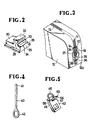
- Figure 1 is a longitudinal cross-sectional view of a lock device according to the present invention;
- Figure 2 is an enlarged perspective view of a closure member of the lock device shown in Figure 1;
- Figure 3 is a fragmentary perspective view, on reduced scale, of Figure 1;
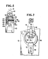
- Figure 4 is a front elevational view of an unlock pin of the lock device;
- Figure 5 is a perspective view of a pull tab useable with the lock device;
- Figure 6 is an enlarged plan view, partly in cross section, of the pull tab shown in Figure 5;
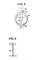
- Figure 7 is a plan view of a modified lock device;
- Figure 8 is a plan view of a lock ring of the modified lock device;
- Figure 9 is a cross-sectional view taken along line IX - IX of Figure 8;
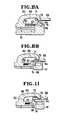
- Figure 10A is a longitudinal cross-sectional view of the lock device with parts shown in locking position;
- Figure 10B is a view similar to Figure 10A, but showing the lock device with parts in unlocking position;
- Figure 11 is a view similar to Figure 10B, but showing a lock ring held in a position to prevent removal from a slider;
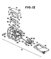
- Figure 12 is an exploded perspective view of a slider constituting part of a modified lock device according to the invention;
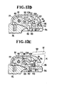
- Figures 13A through 13E are longitudinal cross-sectional views of the slider, illustrative of the sequence of a pull tab detaching operation; and
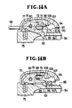
- Figures 14A and 14B are longitudinal cross-sectional views of the slider shown in locked position.
- Figures 1 and 3 show a first embodiment of a slider lock device according to the present invention. The lock device is associated with a
slider 10 of aslide fastener 11 attached to a container orbag 12 for closing anopening 13 in thebag 12. - The
slider 10, as shown in Figure 1, includes a slider body having upper andlower wings 14, 15 joined at their front ends by aneck 16 so as to define therebetween aguide channel 17 for the passage therethrough of a pair of rows ofcoupling elements 18 of theslide fastener 11. The slider body has an arch-shaped lug 19 extending longitudinally over thetop surface 20 of the upper wing 14. The arch-shaped lug 19 has oneend 21 integrally connected with the front end of the upper wing 14, anopposite end 22 of thelug 19 being directed downwardly toward and spaced from thetop surface 20 by apredetermined gap 23. - The slider body further has a
closure member 24 slidably mounted thereon and movable between a closed position to substantially close thegap 23 and an open position to open thegap 23. Theclosure member 24, as shown in Figure 2, has a generallyrectangular body 25 having a pair ofside rails 26. Theclosure member 24 is slidably received in alongitudinal guide groove 27 extending in thetop surface 20 of the upper wing 14 from its rear end and terminating short of thefixed front end 21 of thelug 19, as shown in Figure 1. Theguide groove 27 has an inverted T-shape in cross section which is complementary in contour to theclosure member 24. Acompression coil spring 28 is disposed in anend extension 29 of theguide groove 27 and acts between the slider body and afront end 30 of theclosure member 24 to urge theclosure member 24 into abutment with stoppers 31 (only one shown in Figure 1) disposed on the rear end of the upper wing 14. In this instance, theclosure projection 32 on theclosure member 24 is disposed in confrontation with theend 22 of the arch-shaped lug 19 to substantially close thegap 23. Thus, theclosure member 24 is normally urged to the closed position by thecompression spring 28. - The
closure projection 32 has atransverse recess 33 facing opposite to aspace 34 defined between the arch-shaped lug 19 and thetop surface 20 of the upper wing 14. Thespace 34 is normally closed by theclosure projection 32 and is communicatable with the outside of thelug 19 through thegap 23 when theclosure member 24 is moved forwardly against the bias of thecompression coil spring 28. - The lock device also includes a
lock ring 35 connected by aretainer strap 36 to one side 21a of thebag 12 at a position adjacent to a fastener full-closing position on theslide fastener 11 in which theslider 10 is disposed when theslide fastener 11 is fully closed. - The
lock ring 35 includes a firstcircumferential portion 37 having a thickness which is smaller than thegap 23 so that thelock ring 35 can be threaded through thegap 23 onto thelug 19. Thebase portion 38 of thelock ring 35 which is diametrically opposite to thefirst portion 37 is flattened and stably supported by a loop of theretainer strap 36 with a reinforcing metal strip 39 disposed between theflattened portion 38 and theretainer strap 36. Theretainer strap 36 and the reinforcing strip 39 are rivetted to theside 12a of thebag 12. With the provision of the reinforcing metal strip 39, thelock ring 35 is stably held in position against wobbling. - The lock device of the foregoing construction operates as follows. When the
slider 10 is to be locked, theslider 10 is moved toward the fastener full-closing position until theclosure projection 32 on theclosure member 24 is brought into contact with theportion 37 of thelock ring 35. A further advancing movement of theslider 10 causes theclosure member 24 to be moved by thelocking ring 34 toward its open position whereupon thering portion 37 is inserted through thegap 23 into thespace 34 between thelug 19 and the upper wing 14 of the slider body. Then thering portion 37 is displaced toward thelug 19 as indicated by the arrow A of Figure 1, whereupon theclosure member 24 is returned to its closed position under the force of thecompression coil spring 28. Theslider 10 is thus locked in position against displacement. - To unlock the
slider 10, an unlock pin 40 (Figure 40) is gripped by the user's fingers and, while keeping atip end 41 of thepin 40 in register with therecess 33 in theclosure projection 32, thepin 40 is pushed to displace theclosure member 24 toward its open position until thegap 23 is opened. Thering portion 37 of thelock ring 35 is now allowed to be removed from thespace 34 through thegap 23, thereby to unlock theslider 10. Theunlock pin 40 has anannular head 42 through which a ring of a key-holder (not shown) extends to hold theunlock pin 40 against missing. - The
slider 10 of the afore-mentioned embodiment is not equipped with a pull tab. It is possible to provide the slider body with a pull tab when thespace 34 is large enough to concurrently accommodate a pintle of the pull tab and thering portion 37 of thelock ring 35. The pull tab may be omitted when the slide fastener is opened and closed infrequently or the pull tab is likely to hinder smooth locking and unlocking operation of the lock device. - Figures 5 and 6 show an example of pull tab which is detachably connected to the
lug 19 of theslider 10 shown in Figure 1. Thepull tab 43 includes anunlock pin 44 slidably mounted therein and movable to project from and retracted into thepull tab 43. - The
pull tab 43 includes arectangular body 45 and a hook-shaped link or shackle 46 pivotally supported on thebody 45. Thepull tab body 45 has alongitudinal hole 47 extending along one side edge of thebody 45 and slidably receiving therein abase portion 48 of theshackle 46. Thebase portion 48 has a plurality of barb-like members 49 engageable with anupper shoulder 50 of thehole 47 to prevent theshackle 46 from being detached from thepull tab body 45. Acompression coil spring 51 is disposed in thehole 47 and acts between thepull tab body 45 and a lowermost one of the barb-like members 49 to urge theshackle 46 upwardly until the uppermost barb-like member 49 engages theshoulder 50. In this instance, theshackle 46 projects from outwardly from thebody 45 in a position indicated by the phantom lines in Figure 6 in which thefree end 52 is disposed outside alongitudinal recess 53 in thebody 45. In the phatom-lined position, theshackle 46 is rotatable about thebase postion 48 as indicated by the arrow B in the same figure. The rotating movement of theshackle 46 is prevented when theshackle 46 is depressed until itsfree end 52 is received in therecess 53 as indicated by the solid lines. Theshackle 46 is locked in this solid-lined position by alatch bolt 54 held in mesh with the barb-like members 49 on thebase portion 48. - The
latch bolt 54 is slidably received in atransverse hole 55 extending in thebody 45 perpendicular to thelongitudinal hole 47. Thelatch bolt 54 is normally urged into interlocking engagement with the barb-like members by means of acompression coil spring 56 disposed in thetransverse hole 55 and acting between the rear end of thelatch bolt 54 and aright shoulder 55a of thehole 55. - In order to disengage the
latch bolt 54 from the barb-like members 49, there is provided anactuating pin 57 connected with thelatch bolt 54 and extending therefrom through a transverse window 58 (Figure 5) to the outside of thepull tab body 45, thewindow 58 being formed in thetop surface 45a of thebody 45. In use, theactuating pin 57 is moved in the direction of the arrow C along thewindow 58 to disengate thelatch bolt 54 from the barb-like members 49, whereupon theshackle 46 is projected outwardly under the force of thecompression coil spring 51. - The
unlock pin 44 extends from the rear end of thelatch bolt 54 and is slidably received in atransverse guide hole 59 extending contiguously from thehole 55. Theunlock pin 44 has a length such that theouter end 60 of thepin 44 is fully received in thepull tab body 45 when thelatch bolt 54 is held in mesh with the barb-like members 49, while theouter end 60 prejects laterally from theslider body 45 as indicated by the phantom lines when theactuating pin 57 is brought into engagement with one end of thewindow 58 remote from thebase portion 48 of theshackle 46. Theunlock pin 44 while being held in the projecting position is used to displace theclosure member 24 in the same manner as done by theunlock pin 40 shown in Figure 4. - Figures 7 through 11 inclusive show a modified lock device of the present invention. The lock device is comprised by a part of a
slider 61 which includes anupper wing 62 and an arch-shapedlug 63 disposed thereon with a space 65 (Figure 10A) defined therebetween, thespace 65 communicating with the outside of theslider 61 through agap 64. Theslider 61 further includes aclosure member 66 slidably disposed in thespace 65 for opening and closing thegap 64 by aclosure projection 67. The lock device further has a lockingring 68 connected by aretainer strap 69 to thebag 12. The lockingring 68 is loosely retained by aloop 70 of theretainer strap 69 so that thering 68 is rotatable in the direcion indicated by the arrow D in Figure 7. Thelock ring 68 has a firstcircumferential portion 71 so dimensioned as to pass through thegap 64 and a secondcircumferential portion 72 so dimensioned as to block thegap 64. As shown in Figure 9, the firstcircumferential portion 71 has a circular cross-sectional shape having a diameter R smaller than thegap 64 while the secondcircumferential portion 72 has an oblong cross-sectional shape having a width L. The first and secondcircumferential portions - When the
closure member 66 is moved from its closed position of Figure 10A to the open position of Figure 10B by pushing theclosure member 66 by means of anunlock pin 74, theclosure projection 67 and thefree end 73 of thelug 63 define therebetween thegap 64 which is larger than the diameter R of the firstcircumferential portion 71, thereby allowing passage of thefirst portion 71 through thegap 64. Thegap 64 is smaller than the width L of the secondcircumferential portion 72 and hence blocks passage of thesecond portion 72 therethrough. - In the course of the locking operation, the locking
ring 68 is threaded on thelug 63 of theslider 61 as shown in Figures 7 and 10A and then is turned about itself in the direction of the arrow D through an angle of 180 degrees until the secondcircumferential portion 72 is received in thespace 65, as shown in Figure 8. Theslider 61 is firmly held in interlocking engagement with thelock ring 68. This locking engagement can be maintained even when theclosure member 66 is displaced to the open position as shown in Figure 11. To unlock theslider 61, thelock ring 68 is turned about itself through an angle of 180 degrees until the firstcircumferential portion 71 is received in thespace 65. - Figures 12 - 14B show a
slider 75 which constitutes part of a lock device of the invention. Theslider 75 includes a self-lockingmechanism 76 having avertical lock member 77. - As shown in Figure 12, the
slider 75 includes anupper wing 78 carrying thereon a pair of laterally spacedupstanding supports 79 to which an arch-shapedlug 81 is connected by apin 80. Thelock member 77 is pivotally movable about thepin 80 in opposite directions indicated by the arrow E. - The
lock member 77 has a downwardly projectinglocking prong 82 movable through anaperture 83 in theupper wing 78 into aguide channel 84 for interlocking engagement with coupling element to lock theslider 75 in position against movement. Thelock member 77 is normally urged by acompression coil spring 86 to turn clockwise about thepin 80 into its locking position in which thelocking prong 82 is disposed in theguide channel 84. Thespring 86 acts between the slider body and thefront end 85 of thelock member 77. In Figure 12, thereference numeral 70 denotes a horizontal pin hole formed in thelug 81, 88 a horizontal pin hole in thelock member 77, and 89 a pair of horizontal pin holes in the respective supports 79, thepin 80 being threaded through the pin holes 87 - 89. Thelock member 77 further has arearwardly opening recess 90 for receiving therein apintle 91 of apull tab 92. - The self-locking
mechanism 76 is received in a space between thelug 81 and theupper wing 78 as shown in Figures 13A through 13E. - The
top surface 93 of theupper wing 78 and thefree end 94 of thelug 81 define therebetween agap 95. Aclosure member 96 is slidably mounted in theupper wing 78 and movable between a closed position to close thegap 95 and an open position to open thegap 95. Theclosure member 96, as best shown in Figure 12, has a U-shape and includes afirst closure portion 97 in the shape of a flat land extending around the rear end of theclosure member 96, and a second closure portion composed of a pair of laterally spacedclosure projections 98. The first andsecond closure portions arcuate recesses 99 in which thepintle 91 of thepull tab 92 is temporarily arrested during attachment and detachment with theslider 75. TheU-shaped closure member 96 has a forwardly openingcentral groove 100 receptive of a peripheral wall of theaperture 83. Theclosure member 96 further has a pair oflateral guide rails 101 receivable in a pair oflateral guide grooves 103 when the body of theclosure member 96 is slidably received in acentral guide groove 102 formed in theupper wing 78. Theclosure member 96 is normally urged by acompression coil spring 104 to the closed position in which theclosure member 96 is held in abutment with a pair ofstops 105. - The arch-shaped
lug 81 is hollow in construction and has a U-shaped transverse cross section. Each of thevertical side walls 106 of thehollow lug 81 has a pair of longitudinally spaced, downwardly facing first and secondarcuate recesses projection 109. The first recesses 107 and theprojections 109 are disposed substantially in vertical alignment respectively with thearcuate recesses 99 and theclosure projections 98 when theclosure member 96 is held in its closed position. Thesecond recess 108 mutually receives therein thepintle 91 of thepull tab 92. - The
slider 75 is locked in position by means of a lock ring which is the same in construction as the lockingring 68 shown in Figures 7 - 9. Thelock ring 68 includes a firstcircumferential portion 71 of a circular cross-sectional shape having a diameter substantially equal to the diameter of thepintle 91 of thepull tab 92 so that thisportion 71 can be threaded through thegap 95. Conversely, the secondcircumferential portion 72 of an oblong cross-sectional shape having a width which is larger than thegap 95 and hence blocks thegap 95. - In operation, the
slider 75 is moved to an end position for fully closing a slide fastener by manipulating thepull tab 92. Then, thepull tab 92 is detached from the slider body. Finally theslider 75 is locked in position by thelock ring 68. Successive steps of the pull-tab removing operation are illustrated in Figures 13A to 13E. It is to be noted that detachment of thelock ring 68 can be achieved in the same menner as the removal of thepull tab 92. Likewise, attachment of thepull tab 92 to theslider 75 and locking of theslider 75 by thelock ring 68 can be effected by merely reversing the order of successive steps of operation. - As shown in Figure 13A, the
pull tab 92 extends flatwise over the upper wing of theslider 75 and the lockingprong 82 of thelock member 77 is urged by thespring 87 to project through theaperture 83 into theguide channel 84 for interlocking engagement with the coupling elements (not shown), thereby locking theslider 75 on the coupling element rows. Thepintle 91 of thepull tab 92 is received in therecess 90 in thelock member 77 within the space between thelug 81 and the upper wing of theslider 75. - To detach the
pull tab 92 from theslider 95 and then lock theslider 75 with thelock ring 68, theclosure member 96 is moved forwardly in the direction indicated by the arrow F in Figure 13A by pushing theclosure meber 96 by a pin 40 (see Figure 4) inserted in a pair of laterally aligned guide holes 110 formed in thefirst closure portion 97. With this advancing movement of theclosure member 96, thepintle 91 slides upwardly along an obliquefront face 111 of therespective closure projections 98 to thereby turn thelock member 77 counterclockwise about thepin 80, as shown in Figure 13B. The lockingprong 82 is thus disengaged from the coupling elements of the slide fastener. The upward pivotal movement of thelock member 77 is also realized by simply pulling thepull tab 92 upwardly. - A further advancing movement of the
closure member 96 causes thepintle 91 to be moved past theclosure projections 98 on theclosure member 96 and then slide down in the direction indicated by the arrow G in Figure 13B. Thus thepintle 91 is received in the arcuate recesses 99 (Figure 13A) in theclosure member 96. - Then the
closure member 96 is released from pressure of theunlock pin 40, whereupon theclosure member 96 is moved backwardly in the direction of the arrow H in Figure 13C under the force of the compression coil spring 104 (Figure 12). When theclosure member 96 reaches to its closed position, thepintle 91 is disposed between therecesses 107 in thelug 81 and the correspondingrecesses 99 in theclosure member 96, as shown in Figure 13D. - Thereafter, the
pull tab 92 is pulled upwardly until thepintle 91 is substantially fully retracted in therecesses 107 in thelug 81, as indicated by the arrow J in Figure 13D. While keeping this condition, theclosure member 96 is moved again in the direction of the arrow F. Consequently, thegap 95 is opened as shown in Figure 13E. Now, thepintle 91 is removed from the slider body through the thus openedgap 95 as indicated by the arrow K in the same figure. - The foregoing detachment of the
pull tab 92 is followed by the locking of theslider 75. The slider locking operation is achieved by inserting thecircumferential portion 71 of thelock ring 68 into therecess 90 in thelock member 77 by taking the reverse course of the foregoing pull tab detachment operation. - Then the
lock ring 68 is turned about itself through an angle of 180 degrees until the secondcircumferential portion 72 is received in therecess 90 in thelock member 77 as shown in Figure 14A. Due to its enlarged width, thecircumferential portion 72 is prevented from sliding down theclosure projections 98 as seen from Figure 14B. Thus theslider 75 is firmly locked on thelock ring 68 even when theclosure member 96 is moved to its open position. - To unlock the
slider 75, thelock ring 68 is turned about itself through an angle of 180 degrees until the firstcircumferential portion 71 of thelock ring 68 is disposed in therecess 90 in thelock member 77. Then thelock ring 68 is removed from theslider 75 in the same menner as the pull tab detachment described above. - According to the last-mentioned embodiment, the
slider 75 is locked against movement by the lockingmember 77 on one hand and by thelock ring 68 on the other hand.
Claims (10)
Applications Claiming Priority (2)
| Application Number | Priority Date | Filing Date | Title |
|---|---|---|---|
| JP62023281A JPS63192402A (en) | 1987-02-03 | 1987-02-03 | Lock device for slide fastener |
| JP23281/87 | 1987-02-03 |
Publications (2)
| Publication Number | Publication Date |
|---|---|
| EP0280071A1 true EP0280071A1 (en) | 1988-08-31 |
| EP0280071B1 EP0280071B1 (en) | 1991-12-04 |
Family
ID=12106219
Family Applications (1)
| Application Number | Title | Priority Date | Filing Date |
|---|---|---|---|
| EP88101446A Expired - Lifetime EP0280071B1 (en) | 1987-02-03 | 1988-02-02 | Lock device for slide fastener sliders |
Country Status (8)
| Country | Link |
|---|---|
| US (1) | US4815176A (en) |
| EP (1) | EP0280071B1 (en) |
| JP (1) | JPS63192402A (en) |
| KR (1) | KR910001668B1 (en) |
| DE (1) | DE3866557D1 (en) |
| HK (1) | HK98394A (en) |
| MY (1) | MY102738A (en) |
| PH (1) | PH24965A (en) |
Cited By (3)
| Publication number | Priority date | Publication date | Assignee | Title |
|---|---|---|---|---|
| EP1088490A2 (en) * | 1999-09-30 | 2001-04-04 | Ykk Corporation | Zipper pull of slider for slide fastener |
| EP1541051A1 (en) * | 2003-12-10 | 2005-06-15 | Ykk Corporation | Slider for slider fastener with automatic stopper |
| EP1961325A3 (en) * | 2007-02-20 | 2010-08-25 | YKK Corporation | Slider for slide fastener |
Families Citing this family (15)
| Publication number | Priority date | Publication date | Assignee | Title |
|---|---|---|---|---|
| US5681115A (en) * | 1996-01-02 | 1997-10-28 | Diederich; R. David | Child-resistant locking device for reclosable bag |
| US6189249B1 (en) * | 1997-12-16 | 2001-02-20 | Christopher V. Hughes | Security tag device |
| US7117567B1 (en) * | 2003-02-12 | 2006-10-10 | Briggs & Riley Travelware Llc | Two-part connecting zipper pull |
| US7200901B2 (en) * | 2004-05-18 | 2007-04-10 | Quiksilver, Inc. | Zipper securing devices |
| US7849543B2 (en) * | 2007-04-10 | 2010-12-14 | Mattress Safe, Inc. | Encasement systems |
| DE202009008394U1 (en) * | 2009-06-18 | 2009-10-29 | Balzat, Ernst, Dipl.-Ing. | Blockade zipper |
| DE202009016677U1 (en) | 2009-06-18 | 2010-04-29 | Balzat, Ernst, Dipl.-Ing. | Security zipper |
| CN102548447B (en) * | 2009-11-17 | 2015-04-01 | Ykk株式会社 | Slider for slide fastener |
| US8806678B2 (en) | 2011-01-05 | 2014-08-19 | Skyblue Textiles Llc | Encasement |
| US8615826B2 (en) | 2011-01-05 | 2013-12-31 | Skyblue Textiles Llc | Encasement |
| DE102013106341B3 (en) * | 2013-06-18 | 2014-06-26 | Ernst Balzat | Safety slide fastener, has first locking part comprising attachment surface that is arranged corresponding to underside of slider, and second locking part connected in region of tape end that is arranged at closure tapes |
| EP3076821A4 (en) * | 2013-12-04 | 2018-01-03 | Juno Group Pty Ltd. | Zipper lock |
| US20190241322A1 (en) * | 2016-10-07 | 2019-08-08 | Pollen Gear Llc | Access resistant containers and platform for handling plant |
| WO2019132298A1 (en) * | 2017-12-27 | 2019-07-04 | 이지혜 | Zipper fastener |
| US11627814B2 (en) | 2020-10-16 | 2023-04-18 | Sysco Guest Supply, Llc | Encasements and methods of manufacture |
Citations (8)
| Publication number | Priority date | Publication date | Assignee | Title |
|---|---|---|---|---|
| US2183103A (en) * | 1937-02-09 | 1939-12-12 | Henry C Parker | Slide fastener lock |
| GB558151A (en) * | 1942-06-09 | 1943-12-23 | Eric Hiley Marlow | Improvements in or relating to sliding clasp fasteners |
| US2530438A (en) * | 1947-12-24 | 1950-11-21 | Henry J Modrey | Slide fastener lock |
| US3973419A (en) * | 1975-10-31 | 1976-08-10 | Long Manufacturing Co., Inc. | Combination lock construction for luggage zipper locks, shackle locks and the like |
| GB2000220A (en) * | 1977-06-23 | 1979-01-04 | Yoshida Kogyo Kk | Device for locking a slider of a slide fastener |
| FR2453614A1 (en) * | 1979-04-11 | 1980-11-07 | Eclair Ind | Cursor for slide clasp fastener with decorative plate - is attached by tooth on elastic tongue engaging hole in tab of fastener |
| EP0090370A2 (en) * | 1982-03-25 | 1983-10-05 | Yoshida Kogyo K.K. | Slide fastener slider having detachable pull tab |
| EP0178585A2 (en) * | 1984-10-16 | 1986-04-23 | Yoshida Kogyo K.K. | Slide fastener slider with detachable pull tab |
Family Cites Families (8)
| Publication number | Priority date | Publication date | Assignee | Title |
|---|---|---|---|---|
| FR1005546A (en) * | 1947-08-05 | 1952-04-11 | Valtex | Improvement at closures |
| US2942450A (en) * | 1957-01-31 | 1960-06-28 | Mosler Safe Co | Bag for use with night depositories |
| BE644848A (en) * | 1963-05-03 | 1964-07-01 | ||
| JPS5435764Y2 (en) * | 1975-02-10 | 1979-10-30 | ||
| US3979931A (en) * | 1975-05-08 | 1976-09-14 | Tsui Wai Man | Padlock with double shackle lock |
| JPS5626567Y2 (en) * | 1977-03-03 | 1981-06-24 | ||
| DE3162945D1 (en) * | 1980-06-02 | 1984-05-10 | Ciba Geigy Ag | Chlorine-containing thermoplastic polymers stabilized with amino-thiouracils |
| GB2079362B (en) * | 1980-07-08 | 1984-07-11 | Cmcs Print & Colour Ltd | Sealable fastening device |
-
1987
- 1987-02-03 JP JP62023281A patent/JPS63192402A/en active Granted
-
1988
- 1988-02-02 PH PH36451A patent/PH24965A/en unknown
- 1988-02-02 DE DE8888101446T patent/DE3866557D1/en not_active Expired - Lifetime
- 1988-02-02 EP EP88101446A patent/EP0280071B1/en not_active Expired - Lifetime
- 1988-02-02 KR KR1019880000930A patent/KR910001668B1/en not_active IP Right Cessation
- 1988-02-02 US US07/151,490 patent/US4815176A/en not_active Expired - Fee Related
- 1988-02-03 MY MYPI88000101A patent/MY102738A/en unknown
-
1994
- 1994-09-15 HK HK98394A patent/HK98394A/en unknown
Patent Citations (8)
| Publication number | Priority date | Publication date | Assignee | Title |
|---|---|---|---|---|
| US2183103A (en) * | 1937-02-09 | 1939-12-12 | Henry C Parker | Slide fastener lock |
| GB558151A (en) * | 1942-06-09 | 1943-12-23 | Eric Hiley Marlow | Improvements in or relating to sliding clasp fasteners |
| US2530438A (en) * | 1947-12-24 | 1950-11-21 | Henry J Modrey | Slide fastener lock |
| US3973419A (en) * | 1975-10-31 | 1976-08-10 | Long Manufacturing Co., Inc. | Combination lock construction for luggage zipper locks, shackle locks and the like |
| GB2000220A (en) * | 1977-06-23 | 1979-01-04 | Yoshida Kogyo Kk | Device for locking a slider of a slide fastener |
| FR2453614A1 (en) * | 1979-04-11 | 1980-11-07 | Eclair Ind | Cursor for slide clasp fastener with decorative plate - is attached by tooth on elastic tongue engaging hole in tab of fastener |
| EP0090370A2 (en) * | 1982-03-25 | 1983-10-05 | Yoshida Kogyo K.K. | Slide fastener slider having detachable pull tab |
| EP0178585A2 (en) * | 1984-10-16 | 1986-04-23 | Yoshida Kogyo K.K. | Slide fastener slider with detachable pull tab |
Cited By (8)
| Publication number | Priority date | Publication date | Assignee | Title |
|---|---|---|---|---|
| EP1088490A2 (en) * | 1999-09-30 | 2001-04-04 | Ykk Corporation | Zipper pull of slider for slide fastener |
| EP1088490A3 (en) * | 1999-09-30 | 2002-01-02 | Ykk Corporation | Zipper pull of slider for slide fastener |
| US6430785B1 (en) | 1999-09-30 | 2002-08-13 | Ykk Corporation | Zipper pull of slider for slide fastener |
| EP1541051A1 (en) * | 2003-12-10 | 2005-06-15 | Ykk Corporation | Slider for slider fastener with automatic stopper |
| US7207092B2 (en) | 2003-12-10 | 2007-04-24 | Ykk Corporation | Slider for slide fastener with automatic stopper |
| CN100475075C (en) * | 2003-12-10 | 2009-04-08 | Ykk株式会社 | Slider for slide fastener with automatic stopper |
| EP1961325A3 (en) * | 2007-02-20 | 2010-08-25 | YKK Corporation | Slider for slide fastener |
| US7963008B2 (en) | 2007-02-20 | 2011-06-21 | Ykk Corporation | Slider for slide fastener |
Also Published As
| Publication number | Publication date |
|---|---|
| DE3866557D1 (en) | 1992-01-16 |
| JPS63192402A (en) | 1988-08-09 |
| KR880010209A (en) | 1988-10-07 |
| EP0280071B1 (en) | 1991-12-04 |
| JPH0450805B2 (en) | 1992-08-17 |
| US4815176A (en) | 1989-03-28 |
| PH24965A (en) | 1990-12-26 |
| HK98394A (en) | 1994-09-23 |
| MY102738A (en) | 1992-09-30 |
| KR910001668B1 (en) | 1991-03-18 |
Similar Documents
| Publication | Publication Date | Title |
|---|---|---|
| EP0280071B1 (en) | Lock device for slide fastener sliders | |
| US3971458A (en) | Combination identification card holder and luggage lock | |
| US4976120A (en) | Slider lock assembly | |
| WO2011077544A1 (en) | Reverse opening slide fastener | |
| US20090106951A1 (en) | Zip closure system | |
| KR100196001B1 (en) | Automatic lock slider for concealed slide fastener | |
| CA2017863C (en) | Slide fastener | |
| CA2003005C (en) | Double lockable sliders | |
| EP0917837A2 (en) | Separable bottom stop assembly of slide fastener | |
| US5167052A (en) | Lockable slider for a slide fastener | |
| EP0274105B1 (en) | Slide fastener slider with detachable pull tab | |
| JP2007529236A (en) | Slide fastener | |
| JP3733309B2 (en) | Slider for slide fastener | |
| US5806151A (en) | Lock slider for slide fastener | |
| US4041578A (en) | Automatic lock slider for slide fasteners | |
| EP0512402A1 (en) | Lockable slider for a slide fastener | |
| CN211354117U (en) | Double-opening zipper | |
| EP1300093B1 (en) | A slide fastener | |
| US4112554A (en) | Separable slide fastener with an automatically locking slider | |
| JPH0630012Y2 (en) | Slide fastener open / close fitting | |
| CN213820096U (en) | Slide fastener and woven fabric | |
| US3080632A (en) | Zipper safety fastener | |
| WO2020192468A1 (en) | Tethered fastener | |
| KR100603114B1 (en) | Slide fastener | |
| JPS5820753Y2 (en) | locking device |
Legal Events
| Date | Code | Title | Description |
|---|---|---|---|
| PUAI | Public reference made under article 153(3) epc to a published international application that has entered the european phase |
Free format text: ORIGINAL CODE: 0009012 |
|
| AK | Designated contracting states |
Kind code of ref document: A1 Designated state(s): DE FR GB IT |
|
| 17P | Request for examination filed |
Effective date: 19881130 |
|
| 17Q | First examination report despatched |
Effective date: 19900327 |
|
| GRAA | (expected) grant |
Free format text: ORIGINAL CODE: 0009210 |
|
| AK | Designated contracting states |
Kind code of ref document: B1 Designated state(s): DE FR GB IT |
|
| ITF | It: translation for a ep patent filed |
Owner name: JACOBACCI & PERANI S.P.A. |
|
| ET | Fr: translation filed | ||
| REF | Corresponds to: |
Ref document number: 3866557 Country of ref document: DE Date of ref document: 19920116 |
|
| PLBE | No opposition filed within time limit |
Free format text: ORIGINAL CODE: 0009261 |
|
| STAA | Information on the status of an ep patent application or granted ep patent |
Free format text: STATUS: NO OPPOSITION FILED WITHIN TIME LIMIT |
|
| 26N | No opposition filed | ||
| ITPR | It: changes in ownership of a european patent |
Owner name: CAMBIO RAGIONE SOCIALE;YKK CORPORATION |
|
| PGFP | Annual fee paid to national office [announced via postgrant information from national office to epo] |
Ref country code: FR Payment date: 19950120 Year of fee payment: 8 |
|
| REG | Reference to a national code |
Ref country code: FR Ref legal event code: CD |
|
| PGFP | Annual fee paid to national office [announced via postgrant information from national office to epo] |
Ref country code: GB Payment date: 19950124 Year of fee payment: 8 |
|
| PGFP | Annual fee paid to national office [announced via postgrant information from national office to epo] |
Ref country code: DE Payment date: 19950331 Year of fee payment: 8 |
|
| PG25 | Lapsed in a contracting state [announced via postgrant information from national office to epo] |
Ref country code: GB Effective date: 19960202 |
|
| GBPC | Gb: european patent ceased through non-payment of renewal fee |
Effective date: 19960202 |
|
| PG25 | Lapsed in a contracting state [announced via postgrant information from national office to epo] |
Ref country code: FR Effective date: 19961031 |
|
| PG25 | Lapsed in a contracting state [announced via postgrant information from national office to epo] |
Ref country code: DE Effective date: 19961101 |
|
| REG | Reference to a national code |
Ref country code: FR Ref legal event code: ST |
|
| PG25 | Lapsed in a contracting state [announced via postgrant information from national office to epo] |
Ref country code: IT Free format text: LAPSE BECAUSE OF NON-PAYMENT OF DUE FEES;WARNING: LAPSES OF ITALIAN PATENTS WITH EFFECTIVE DATE BEFORE 2007 MAY HAVE OCCURRED AT ANY TIME BEFORE 2007. THE CORRECT EFFECTIVE DATE MAY BE DIFFERENT FROM THE ONE RECORDED. Effective date: 20050202 |