EP0280023A2 - Opening arrangement on packing containers - Google Patents
Opening arrangement on packing containers Download PDFInfo
- Publication number
- EP0280023A2 EP0280023A2 EP88100573A EP88100573A EP0280023A2 EP 0280023 A2 EP0280023 A2 EP 0280023A2 EP 88100573 A EP88100573 A EP 88100573A EP 88100573 A EP88100573 A EP 88100573A EP 0280023 A2 EP0280023 A2 EP 0280023A2
- Authority
- EP
- European Patent Office
- Prior art keywords
- pipe
- opening arrangement
- opening
- accordance
- packing container
- Prior art date
- Legal status (The legal status is an assumption and is not a legal conclusion. Google has not performed a legal analysis and makes no representation as to the accuracy of the status listed.)
- Granted
Links
Images


Classifications
-
- B—PERFORMING OPERATIONS; TRANSPORTING
- B65—CONVEYING; PACKING; STORING; HANDLING THIN OR FILAMENTARY MATERIAL
- B65D—CONTAINERS FOR STORAGE OR TRANSPORT OF ARTICLES OR MATERIALS, e.g. BAGS, BARRELS, BOTTLES, BOXES, CANS, CARTONS, CRATES, DRUMS, JARS, TANKS, HOPPERS, FORWARDING CONTAINERS; ACCESSORIES, CLOSURES, OR FITTINGS THEREFOR; PACKAGING ELEMENTS; PACKAGES
- B65D5/00—Rigid or semi-rigid containers of polygonal cross-section, e.g. boxes, cartons or trays, formed by folding or erecting one or more blanks made of paper
- B65D5/42—Details of containers or of foldable or erectable container blanks
- B65D5/72—Contents-dispensing means
- B65D5/74—Spouts
- B65D5/746—Spouts formed separately from the container
- B65D5/747—Spouts formed separately from the container with means for piercing or cutting the container wall or a membrane connected to said wall
- B65D5/748—Spouts formed separately from the container with means for piercing or cutting the container wall or a membrane connected to said wall a major part of the container wall or membrane being left inside the container after the opening
-
- B—PERFORMING OPERATIONS; TRANSPORTING
- B65—CONVEYING; PACKING; STORING; HANDLING THIN OR FILAMENTARY MATERIAL
- B65D—CONTAINERS FOR STORAGE OR TRANSPORT OF ARTICLES OR MATERIALS, e.g. BAGS, BARRELS, BOTTLES, BOXES, CANS, CARTONS, CRATES, DRUMS, JARS, TANKS, HOPPERS, FORWARDING CONTAINERS; ACCESSORIES, CLOSURES, OR FITTINGS THEREFOR; PACKAGING ELEMENTS; PACKAGES
- B65D5/00—Rigid or semi-rigid containers of polygonal cross-section, e.g. boxes, cartons or trays, formed by folding or erecting one or more blanks made of paper
- B65D5/42—Details of containers or of foldable or erectable container blanks
- B65D5/72—Contents-dispensing means
-
- B—PERFORMING OPERATIONS; TRANSPORTING
- B67—OPENING, CLOSING OR CLEANING BOTTLES, JARS OR SIMILAR CONTAINERS; LIQUID HANDLING
- B67B—APPLYING CLOSURE MEMBERS TO BOTTLES JARS, OR SIMILAR CONTAINERS; OPENING CLOSED CONTAINERS
- B67B7/00—Hand- or power-operated devices for opening closed containers
- B67B7/24—Hole-piercing devices
- B67B7/26—Hole-piercing devices combined with spouts
Definitions
- the present invention relates to an opening arrangement on a packing container, preferably of the type which is intended for non-returnable usage and is manufactured from a flexible, laminated packing material.
- a packing laminate is used which comprises a central carrier layer of fibrous material, covered on both sides by homogeneous layers of thermoplastic material.
- the packing material is converted with the help of packing machines through folding and sealing to individual packing containers filled with liquid contents (e.g. milk).
- the packing containers have different types of opening arrangements, which in their simplest form may consist of a printed opening indication and which on more sophisticated packing containers may be constituted of a prepared pouring opening which can be exposed and reclosed with the help of a pull-off cover strip.
- an opening arrangement on packing containers has been given the characteristic that it comprises a pouring pipe joined to the wall of the packing container which in its side facing towards the packing container wall has an opening, and a slide displaceable in the pipe with a tearing component, which in the closed position of the opening arrangement is located in the pipe, and in the open position of the opening arrangement extends out through the opening of the pipe and into the packing container so that the inner space of the latter is in communication with the environment via the pipe.
- Opening arrangement which is manufactured separately from thermoplastic material and is assembled thereafter on the packing container, is simple to open and to reclose and has very good pouring properties. Opening arrangements of this main type, that is to say opening arrangements with a defined outlet duct, may also be used to combine several conventional packing containers to one another and in this manner create a packing container of a large volume.
- the opening arrangement in accordance with the invention comprises two co-operating main parts, namely first main part in the form of a slide 1 and a second main part in the form of a pouring pipe 2. Both parts are manufactured from a plastic material, e.g. polyethylene, and are designed so that they can be assembled inside each other by pushing the slide 1 in through the one open end of the pouring pipe 2 (the rear end, that is to say the righthand one, in the Figure).
- the slide 1 is of substantially rectangular shape and comprises a bottom surface 3 with longitudinal edges 4 which extend at a substantially right angle upwards from the bottom surface 3.
- a gripping element 5 is located which in the preferred embodiment described is of substantially circular ring-shape, but which, of course, may be of any other suitable shape, e.g. a shape which indicates to the consumer the correct direction of pulling.
- a projecting wall part in the form of a flap 6 which is attached to the one edge 4 of the slide by means of a weakened portion serving as a hinge.
- the flap is of a length which corresponds to the width of the slide and a height which corresponds to the height of the edges 4.
- the bottom surface 3 is provided with a substantially centrally placed, rectangular opening 7 and two openings 8,9 located on either side.
- a tearing component 10,11 which is formed in one piece with the slide and is connected to the bottom surface of the same at one edge of the respective opening 8,9, more particularly the remote edge in relation to the gripping element 5.
- the two tearing components 10 are substantially arc-shaped and oriented so that the highest point of their arched or convex surface is at a level with, or slightly below, the upper limiting line of the two edges 4, whilst the free ends of the tearing components 10 facing towards the gripping element 5, are substantially in a plane with the bottom surface 3.
- the ends of the tearing component 10,11 facing towards the gripping element 5 have a number of projecting, pointed portions which are designed as relatively sharp "edges" or "ploughs".
- the second main part 9 of the opening arrangement, or the pouring pipe 2 is of a length which by and large coincides with the length of the bottom surface 3 and is of square cross-section, the width and height of which substantially correspond to, or slightly exceed, the width and height respectively of the bottom surface 3 and the edges 4 of the slide 1. It is thus possible to push the slide 1 into the pipe 2 in such a manner that the slide can be pushed to and fro in the pipe with small resistance by means of the gripping element 5.
- the bottom 14 of the pouring pipe 2 is provided with two openings 12,13 which are located at some distance from each other and have between them an unbroken portion of the bottom surface 14.
- the upper wall surface 15 of the pipe is provided with two projections or ridges 16,17 extending in longitudinal direction of the pipe which are formed by pressing down the upper wall surface 15 to the desired depth.
- the height of the ridges 16,17 mainly corresponds to half the distance between the bottom surface 14 of the pipe and its upper wall surface 15, and the length of the ridges corresponds substantially to the corresponding longitudinal dimension of the openings 12,13,
- the packing container is of substantially known design and is produced by folding, forming and sealing of a flexible packing laminate which, for example, may comprise a central carrier layer of fibrous material which is coated on both sides with thin layers of thermoplastic material, e.g. polyethylene, and possibly also further layers of barrier type, e.g. aluminium foil.
- the material of the packing container 20 may possibly be provided on the top side of the packing container, or at the point where the opening arrangement in accordance with the invention is intended to be attached, with weakened areas 21 in which the stiffening fibrous material has been excluded so that only comparatively thin layers of thermoplastic material and possibly aluminium foil remain.
- the two weakened areas 21 are designed and located so that after application of the opening arrangement they largely coincide with the extent and the location of the two openings 12,13 provided in the bottom surface 14 of the pouring pipe.
- the opening arrangement On application of the opening arrangement in accordance with the invention to a previously manufactured plane top surface of a packing container known in itself, the opening arrangement is positioned as shown in Fig.3 and is joined to the top wall surface with the help of the adhesive, mentioned earlier, applied to the bottom surface of the pouring pipe, which prior to application has been activated e.g. through the supply of heat.
- the front end of the opening arrangement that is to say the end provided with the flap 6 will extend slightly (1-5 mm) outside an adjacent edge of the top surface of the packing container whilst the gripping element 5, preferably, should not extend outside the opposite edge surface of the packing container.
- the consumer gets hold of the projecting gripping element 5 and pulls the same backwards until the slide 1 has been partly pulled out of the pouring pipe 2.
- the upper surfaces of the two tearing components 10,11 come into contact with the two ridges 16,17 extending downwards from the upper wall surface 15 of the pipe.
- the tearing components 10,11 will be forced in underneath the two ridges 16,17 until the space between the lower surface of the ridges and the bottom surface 14 of the pouring pipe becomes too small for the curved tearing components 10,11 still to find room.
- a continued pull-out of the slide 1 with the help of the gripping element 5 is prevented when the tearing components 10,11 reach the rear edge of the openings 12,13 in the bottom surface 14 of the pipe, in which position the tearing components 10,11 have penetrated and practically completely pushed aside the layers in the weakened areas 21 of the packing container, so that the interior of the packing container, vie the openings produced, and the pouring pipe 2 are in communication with the environment.
- the slide 1 When the consumer, after pouring out of the desired quantity of contents, wishes to reclose the packing container, the slide 1 is returned with the help of the gripping element 5 to its original position inside the pouring pipe 2. In so doing the two tearing components 10,11,owing to contact with the front edge of the opening 12,13 will be swivelled up again, out of the openings so that the slide 1 can revert to its original position, whereby the unbroken parts of the bottom surface 3 of the slide will cover the broken up portions of the packing container wall, so that the two openings 12,13 are completely covered and the communication between the interior of the packing container and the environment is completely cut off.
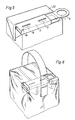
- Fig.5 The preferred placing of the opening arrangement in accordance with the invention on a packing container as well-known parallelepipedic type is shown in Fig.5, where the opening arrangement is in its opened position.
- the opening arrangement can be used of course on any suitable type of packing container whatever, and in Fig.6 is shown an embodiment where the opening arrangement is used so as to make possible the opening of, and the pouring out of contents from, a double package which consists of two individual packing containers (part containers) of known type placed tightly adjoining each other and connected to each other.
- the opening arrangement which is of the main type described above or, in any case, is of the type which comprises a pouring pipe or an outlet duct, extends over the top sides of both part containers and connects openings on the two part containers with one another, the pouring pipe acting as a joint outlet duct.
- the slide of the opening arrangement here is provided with a suitable number of tearing components (with corresponding openings in the pouring pipe),e.g. four.
- the embodiment described earlier with two tearing components for each packing container assumes that a special air opening is necessary, but this is by no means always the case, and it is only a requirement, therefore, that one opening with associated tearing component should be present on each one of the two packing containers connected to each other.
- the two part containers forming the double packing container thus are both opened when the consumer manoeuvers the opening arrangement, and on emptying out the contents of the package, the same flows through the same pouring pipe from both part containers.
- the part containers preferably are wrapped by a common plastic film which is shrunk around the packing containers as well as the opening arrangement and has holes for both ends of the opening arrangement.
- the plastic film here serves on the one hand as a stabilizing wrapping, on the other hand as a decorative film for the two unprinted part containers.
- the arrangement appropriately is also provided with a handle, e.g. a strap extending at a distance over the top of the packing containers (Fig.6).
- the opening arrangement in accordance with the invention makes possible in this manner the manufacture of packing containers with e.g. double volume by combining several known packing containers to a unit, which allows in a simple manner and at small cost to adjust the manufacture rapidly to larger package volumes.
Landscapes
- Engineering & Computer Science (AREA)
- Mechanical Engineering (AREA)
- Cartons (AREA)
- Control And Other Processes For Unpacking Of Materials (AREA)
- Supplying Of Containers To The Packaging Station (AREA)
- Auxiliary Devices For And Details Of Packaging Control (AREA)
- Closures For Containers (AREA)
- Packages (AREA)
- Confectionery (AREA)
Abstract
Description
- The present invention relates to an opening arrangement on a packing container, preferably of the type which is intended for non-returnable usage and is manufactured from a flexible, laminated packing material. In the manufacture of such packing containers usually a packing laminate is used which comprises a central carrier layer of fibrous material, covered on both sides by homogeneous layers of thermoplastic material. The packing material is converted with the help of packing machines through folding and sealing to individual packing containers filled with liquid contents (e.g. milk). The packing containers have different types of opening arrangements, which in their simplest form may consist of a printed opening indication and which on more sophisticated packing containers may be constituted of a prepared pouring opening which can be exposed and reclosed with the help of a pull-off cover strip.
- Known types of opening arrangements for packing containers of the non-returnable type are subject to various disadvantages, e.g. that they are difficult to open or to reclose, that with certain combinations of contents and type of pouring opening it is difficult to empty out the contents of the package in a collective, even jet or that they are too complicated and expensive to manufacture. It is a general which in the packing branch,therefore, to provide an optimum opening arrangement which overcomes the aforementioned problems.
- It is an object of the present invention to provide an opening arrangement on packing containers, this opening arrangement preferably being capable of being combined with known types of packing containers, and to overcome the disadvantages which affected previous arrangements.
- It is further object of the present invention to provide an opening arrangement which can be opened by a single movement of the hand and which can be reclosed in an effective manner by a movement of the hand in opposite direction.
- It is a further object of the present invention to provide an opening arrangement which has good pouring properties also in the case of those types of contents which cause difficulties in combination with known types of opening arrangements.
- It is further object of the present invention to provide an opening arrangement which is simple to manufacture and to assemble and which is inexpensive in relation to the total cost of the package.
- It is a further object of the present invention to provide an opening arrangement which makes it possible in a rational and cost-effective manner to combine several individual packing containers with one another so that they can be handled and used by the consumer as a single packing container of a large volume.
- These and other objects have been achieved through the invention in that an opening arrangement on packing containers has been given the characteristic that it comprises a pouring pipe joined to the wall of the packing container which in its side facing towards the packing container wall has an opening, and a slide displaceable in the pipe with a tearing component, which in the closed position of the opening arrangement is located in the pipe, and in the open position of the opening arrangement extends out through the opening of the pipe and into the packing container so that the inner space of the latter is in communication with the environment via the pipe.
- Preferred embodiments of the opening arrangement in accordance with the invention have been given, moreover, the characteristics which are evident from the subsidiary claims.
- This opening arrangement, which is manufactured separately from thermoplastic material and is assembled thereafter on the packing container, is simple to open and to reclose and has very good pouring properties. Opening arrangements of this main type, that is to say opening arrangements with a defined outlet duct, may also be used to combine several conventional packing containers to one another and in this manner create a packing container of a large volume.
- A preferred embodiment of the opening arrangement in accordance with the invention will now be described in more detail with reference to the attached schematic drawings which only show the details indispensable for an understanding of the invention.
- Fig. 1 shows in perspective a main part of the opening arrangement in accordance with the invention.
- Fig. 2 shows in perspective and partly in section another main part of the opening arrangement in accordance with the invention.
- Fig. 3 shows in section the main parts of the opening arrangement shown in Fig.1 and Fig.2 after assembly, but before application to a packing ccontainer, whose top part is also shown in section.
- Fig. 4 is a section through the opening arrangement in accordance with the invention in opened during pouring out of the contents from a packing container.
- Fig. 5 shows in perspective the opening arrangement in accordance with the invention assembled on a packing container.
- Fig. 6 shows an embodiment of the opening arrangement in accordance with the invention assembled on another type of packing container which comprises two part containers.
- The opening arrangement in accordance with the invention comprises two co-operating main parts, namely first main part in the form of a slide 1 and a second main part in the form of a pouring pipe 2. Both parts are manufactured from a plastic material, e.g. polyethylene, and are designed so that they can be assembled inside each other by pushing the slide 1 in through the one open end of the pouring pipe 2 (the rear end, that is to say the righthand one, in the Figure). The slide 1 is of substantially rectangular shape and comprises a
bottom surface 3 withlongitudinal edges 4 which extend at a substantially right angle upwards from thebottom surface 3. At one (rear) end of the slide agripping element 5 is located which in the preferred embodiment described is of substantially circular ring-shape, but which, of course, may be of any other suitable shape, e.g. a shape which indicates to the consumer the correct direction of pulling. At the opposite, front, end of the slide there is a projecting wall part in the form of a flap 6 which is attached to the oneedge 4 of the slide by means of a weakened portion serving as a hinge. The flap is of a length which corresponds to the width of the slide and a height which corresponds to the height of theedges 4. - The
bottom surface 3 is provided with a substantially centrally placed,rectangular opening 7 and twoopenings 8,9 located on either side. In each of the latter two there is atearing component respective opening 8,9, more particularly the remote edge in relation to thegripping element 5. The twotearing components 10 are substantially arc-shaped and oriented so that the highest point of their arched or convex surface is at a level with, or slightly below, the upper limiting line of the twoedges 4, whilst the free ends of thetearing components 10 facing towards thegripping element 5, are substantially in a plane with thebottom surface 3. The ends of thetearing component gripping element 5 have a number of projecting, pointed portions which are designed as relatively sharp "edges" or "ploughs". - The second main part 9 of the opening arrangement, or the pouring pipe 2, is of a length which by and large coincides with the length of the
bottom surface 3 and is of square cross-section, the width and height of which substantially correspond to, or slightly exceed, the width and height respectively of thebottom surface 3 and theedges 4 of the slide 1. It is thus possible to push the slide 1 into the pipe 2 in such a manner that the slide can be pushed to and fro in the pipe with small resistance by means of thegripping element 5. - The
bottom 14 of the pouring pipe 2 is provided with twoopenings bottom surface 14. Above the twoopenings upper wall surface 15 of the pipe is provided with two projections orridges upper wall surface 15 to the desired depth. The height of theridges bottom surface 14 of the pipe and itsupper wall surface 15, and the length of the ridges corresponds substantially to the corresponding longitudinal dimension of theopenings - When the two main parts 1,2 of the opening arrangement have been assembled by virtue of the slide 1 having seen pushed into the pouring pipe 2 so that only the gripping
element 5 projects from the one end of the pouring opening, the opening arrangement is ready to be assembled on a prefabricated packing container filled with liquid contents (Fig.3). The packing container is of substantially known design and is produced by folding, forming and sealing of a flexible packing laminate which, for example, may comprise a central carrier layer of fibrous material which is coated on both sides with thin layers of thermoplastic material, e.g. polyethylene, and possibly also further layers of barrier type, e.g. aluminium foil. The material of thepacking container 20 may possibly be provided on the top side of the packing container, or at the point where the opening arrangement in accordance with the invention is intended to be attached, with weakenedareas 21 in which the stiffening fibrous material has been excluded so that only comparatively thin layers of thermoplastic material and possibly aluminium foil remain. The two weakenedareas 21 are designed and located so that after application of the opening arrangement they largely coincide with the extent and the location of the twoopenings bottom surface 14 of the pouring pipe. On application of the opening arrangement in accordance with the invention to a previously manufactured plane top surface of a packing container known in itself, the opening arrangement is positioned as shown in Fig.3 and is joined to the top wall surface with the help of the adhesive, mentioned earlier, applied to the bottom surface of the pouring pipe, which prior to application has been activated e.g. through the supply of heat. After the application the front end of the opening arrangement, that is to say the end provided with the flap 6, will extend slightly (1-5 mm) outside an adjacent edge of the top surface of the packing container whilst thegripping element 5, preferably, should not extend outside the opposite edge surface of the packing container. With such a placing it will be possible simply to pour out the contents without any risk of their running along the outside of the packing container at the same time as, thanks to the opening arrangement not unnecessarily extending outside the contours of the top surface of the packing container, it is optimally protected during handling of the packing container, so that damage or unintentional opening are prevented. - When the opening arrangement in accordance with the invention has been assembled on a packing container and is to be used by the consumer for pouring out the liquid contents of the packing container, the consumer gets hold of the projecting
gripping element 5 and pulls the same backwards until the slide 1 has been partly pulled out of the pouring pipe 2. In so doing the upper surfaces of the twotearing components ridges upper wall surface 15 of the pipe. On continued displacement of the slide 1 in the direction of thegripping element 5, thetearing components ridges bottom surface 14 of the pouring pipe becomes too small for thecurved tearing components openings bottom surfae 14 of the pouring pipe and, in a ploughlike manner, further through the two weakenedareas 21 in the upper wall surface of the packing container. As soon as the edgebearing front end of thetearing components areas 21, thetearing components 10 will continue to swivel downwards, the weakened connecting surface between therespective tearing components bottom surface 3 of the slide serving as a hinge. A continued pull-out of the slide 1 with the help of thegripping element 5 is prevented when thetearing components openings bottom surface 14 of the pipe, in which position thetearing components areas 21 of the packing container, so that the interior of the packing container, vie the openings produced, and the pouring pipe 2 are in communication with the environment. - In connection with the pull-out of the slide 1 a
wall part 22 located at the transition betwen thegripping element 5 and thebottom surface 3 has been removed from the open rear end of the pouring pipe 2, so that the passage between the surrounding air and the interior of the packing container has been freed. In corresponding manner the flap 6 located at the opposite end of the slide 1, through the effect of thelip 18, has been forced to the slide, so that the pouring opening of the pouring pipe has been freed and pouring out of the contents can take place, the volume emptied out from the packing container being compensated through intake of surrounding air via the rear opening of the opening arrangement. - When the consumer, after pouring out of the desired quantity of contents, wishes to reclose the packing container, the slide 1 is returned with the help of the
gripping element 5 to its original position inside the pouring pipe 2. In so doing the twotearing components opening bottom surface 3 of the slide will cover the broken up portions of the packing container wall, so that the twoopenings pouring pipe 15, so that the flap is brought down at a right angle against theedge 4 and thereby completely covers ther pouring opening of the pipe 2 so that extraneous objects such as dirt or the like are prevented from penetrating from the outside into the pipe. - On renewed opening of the packing container the two
tearing components - The preferred placing of the opening arrangement in accordance with the invention on a packing container as well-known parallelepipedic type is shown in Fig.5, where the opening arrangement is in its opened position. The opening arrangement can be used of course on any suitable type of packing container whatever, and in Fig.6 is shown an embodiment where the opening arrangement is used so as to make possible the opening of, and the pouring out of contents from, a double package which consists of two individual packing containers (part containers) of known type placed tightly adjoining each other and connected to each other. The opening arrangement, which is of the main type described above or, in any case, is of the type which comprises a pouring pipe or an outlet duct, extends over the top sides of both part containers and connects openings on the two part containers with one another, the pouring pipe acting as a joint outlet duct. The slide of the opening arrangement here is provided with a suitable number of tearing components (with corresponding openings in the pouring pipe),e.g. four.The embodiment described earlier with two tearing components for each packing container assumes that a special air opening is necessary, but this is by no means always the case, and it is only a requirement, therefore, that one opening with associated tearing component should be present on each one of the two packing containers connected to each other. The two part containers forming the double packing container thus are both opened when the consumer manoeuvers the opening arrangement, and on emptying out the contents of the package, the same flows through the same pouring pipe from both part containers. The part containers preferably are wrapped by a common plastic film which is shrunk around the packing containers as well as the opening arrangement and has holes for both ends of the opening arrangement. The plastic film here serves on the one hand as a stabilizing wrapping, on the other hand as a decorative film for the two unprinted part containers. The arrangement appropriately is also provided with a handle, e.g. a strap extending at a distance over the top of the packing containers (Fig.6). The opening arrangement in accordance with the invention makes possible in this manner the manufacture of packing containers with e.g. double volume by combining several known packing containers to a unit, which allows in a simple manner and at small cost to adjust the manufacture rapidly to larger package volumes.
Claims (14)
Priority Applications (1)
| Application Number | Priority Date | Filing Date | Title |
|---|---|---|---|
| AT88100573T ATE86573T1 (en) | 1987-02-24 | 1988-01-16 | OPENING DEVICE ON PACKAGING CONTAINERS. |
Applications Claiming Priority (2)
| Application Number | Priority Date | Filing Date | Title |
|---|---|---|---|
| GB8704289 | 1987-02-24 | ||
| GB8704289A GB2202213B (en) | 1987-02-24 | 1987-02-24 | Opening apparatus for packing containers |
Publications (3)
| Publication Number | Publication Date |
|---|---|
| EP0280023A2 true EP0280023A2 (en) | 1988-08-31 |
| EP0280023A3 EP0280023A3 (en) | 1989-03-15 |
| EP0280023B1 EP0280023B1 (en) | 1993-03-10 |
Family
ID=10612825
Family Applications (1)
| Application Number | Title | Priority Date | Filing Date |
|---|---|---|---|
| EP88100573A Expired - Lifetime EP0280023B1 (en) | 1987-02-24 | 1988-01-16 | Opening arrangement on packing containers |
Country Status (10)
| Country | Link |
|---|---|
| US (1) | US4838428A (en) |
| EP (1) | EP0280023B1 (en) |
| JP (1) | JP2532553B2 (en) |
| AT (1) | ATE86573T1 (en) |
| AU (1) | AU596730B2 (en) |
| CA (1) | CA1299522C (en) |
| DE (1) | DE3878944T2 (en) |
| ES (1) | ES2038699T3 (en) |
| GB (1) | GB2202213B (en) |
| SU (1) | SU1595336A3 (en) |
Cited By (6)
| Publication number | Priority date | Publication date | Assignee | Title |
|---|---|---|---|---|
| EP0369215A1 (en) * | 1988-11-16 | 1990-05-23 | Tetra Alfa Holdings S.A. | Opening arrangement for cardboard package |
| US6302289B1 (en) | 1999-01-07 | 2001-10-16 | Tetra Laval Holdings & Finance S.A. | Safety device in opening arrangements for packaging containers |
| WO2006122849A1 (en) | 2005-05-18 | 2006-11-23 | Sig Technology Ag | Pouring element for cardboard/plastic composite packagings and packaging provided with said pouring element |
| NL2001936C (en) * | 2008-08-29 | 2010-03-11 | Bin Innovations Bv | LIQUID HOLDER. |
| NL2003369C2 (en) * | 2009-08-20 | 2011-02-22 | Weasy Pack Internat Ltd | PURCHASE DEVICE AND PACKAGING PACKED WITH A PURCHASE DEVICE. |
| NL2009849C2 (en) * | 2012-11-20 | 2014-05-21 | Robert Sebastiaan Beens | OPENING DEVICE FOR A LIQUID HOLDER AND LIQUID HOLDER. |
Families Citing this family (12)
| Publication number | Priority date | Publication date | Assignee | Title |
|---|---|---|---|---|
| JPH0390864U (en) * | 1989-12-27 | 1991-09-17 | ||
| JPH0416134U (en) * | 1990-05-30 | 1992-02-10 | ||
| SE9200391L (en) * | 1992-02-11 | 1993-08-12 | Tetra Laval Holdings & Finance | Opening device |
| SE9304200L (en) * | 1993-12-17 | 1995-01-16 | Tetra Laval Holdings & Finance | Opening device for liquid packaging |
| PT760339E (en) * | 1994-06-02 | 2001-09-28 | Tetra Laval Holdings & Finance | DEVICE FOR OPENING THE NOZZLE SEAL FOR A LIQUID CONTAINER |
| SE509810C2 (en) * | 1997-07-04 | 1999-03-08 | Tetra Laval Holdings & Finance | Opening device for packaging containers |
| DE19805030C2 (en) * | 1998-02-09 | 2003-03-27 | Sig Combibloc Gmbh | Resealable pouring element and flat gable composite package provided with it |
| DE19811528C2 (en) * | 1998-03-17 | 2003-12-18 | Sig Combibloc Gmbh | Resealable pouring element for beverage packs and beverage packs provided therewith |
| PT1328444E (en) | 2000-10-03 | 2005-05-31 | Weasy Pack Internat Ltd | CONTAINER GIFTED WITH FLEXIBLE CLOSURE |
| US7237455B2 (en) * | 2005-07-05 | 2007-07-03 | Wining Taylors, Llc | Bottle stop remover |
| NL2010105C2 (en) * | 2013-01-10 | 2014-07-15 | Trendzpak Ltd | PACKAGING PACKAGE FOR A FLUID, AND PURCHASE FOR THAT. |
| US12122572B2 (en) * | 2017-03-13 | 2024-10-22 | Paha Designs, Llc | Pressure equalization apparatus for a container and methods associated therewith |
Family Cites Families (10)
| Publication number | Priority date | Publication date | Assignee | Title |
|---|---|---|---|---|
| US3185357A (en) * | 1963-10-29 | 1965-05-25 | Merkel Hans | Dispensing device for granular or pulverulent materials |
| US2781156A (en) * | 1954-10-13 | 1957-02-12 | William H Wallo | Soap dispenser |
| US2921720A (en) * | 1958-05-07 | 1960-01-19 | Joseph A Malachick | Visual cereal dispenser |
| US3024950A (en) * | 1959-09-18 | 1962-03-13 | Wallenstein & Spangenberg | Dispensing unit for selectively pouring or sifting pulverulent material |
| US3118577A (en) * | 1960-10-14 | 1964-01-21 | Alton E Estabrook | Closure for material dispensing device |
| US3105620A (en) * | 1960-12-14 | 1963-10-01 | Allied Chem | Flow controller |
| US3696977A (en) * | 1971-04-21 | 1972-10-10 | Johnson & Son Inc S C | Stretch elastomer valve |
| US4197985A (en) * | 1979-03-02 | 1980-04-15 | Champion International Corporation | Tamperproof dispensing carton and blank therefore |
| US4483464A (en) * | 1980-10-16 | 1984-11-20 | Toppan Printing Co., Ltd. | Container with a pouring spout |
| JPS59181457U (en) * | 1983-05-18 | 1984-12-04 | 株式会社リコー | Toner cartridge container |
-
1987
- 1987-02-24 GB GB8704289A patent/GB2202213B/en not_active Expired - Fee Related
-
1988
- 1988-01-16 DE DE8888100573T patent/DE3878944T2/en not_active Expired - Fee Related
- 1988-01-16 AT AT88100573T patent/ATE86573T1/en not_active IP Right Cessation
- 1988-01-16 EP EP88100573A patent/EP0280023B1/en not_active Expired - Lifetime
- 1988-01-16 ES ES198888100573T patent/ES2038699T3/en not_active Expired - Lifetime
- 1988-01-22 US US07/147,299 patent/US4838428A/en not_active Expired - Lifetime
- 1988-01-27 CA CA000557509A patent/CA1299522C/en not_active Expired - Fee Related
- 1988-02-23 AU AU12058/88A patent/AU596730B2/en not_active Ceased
- 1988-02-23 SU SU884355207A patent/SU1595336A3/en active
- 1988-02-23 JP JP63038797A patent/JP2532553B2/en not_active Expired - Lifetime
Cited By (8)
| Publication number | Priority date | Publication date | Assignee | Title |
|---|---|---|---|---|
| EP0369215A1 (en) * | 1988-11-16 | 1990-05-23 | Tetra Alfa Holdings S.A. | Opening arrangement for cardboard package |
| US6302289B1 (en) | 1999-01-07 | 2001-10-16 | Tetra Laval Holdings & Finance S.A. | Safety device in opening arrangements for packaging containers |
| WO2006122849A1 (en) | 2005-05-18 | 2006-11-23 | Sig Technology Ag | Pouring element for cardboard/plastic composite packagings and packaging provided with said pouring element |
| EA010999B1 (en) * | 2005-05-18 | 2008-12-30 | Зиг Технологи Аг | Pouring element for cardboard/plastic composite packagings and packaging provided with said pouring element |
| NL2001936C (en) * | 2008-08-29 | 2010-03-11 | Bin Innovations Bv | LIQUID HOLDER. |
| NL2003369C2 (en) * | 2009-08-20 | 2011-02-22 | Weasy Pack Internat Ltd | PURCHASE DEVICE AND PACKAGING PACKED WITH A PURCHASE DEVICE. |
| WO2011021934A1 (en) * | 2009-08-20 | 2011-02-24 | Weasy Pack International Ltd. | Pouring device and pouring package provided with a pouring device |
| NL2009849C2 (en) * | 2012-11-20 | 2014-05-21 | Robert Sebastiaan Beens | OPENING DEVICE FOR A LIQUID HOLDER AND LIQUID HOLDER. |
Also Published As
| Publication number | Publication date |
|---|---|
| AU1205888A (en) | 1988-08-25 |
| ATE86573T1 (en) | 1993-03-15 |
| EP0280023A3 (en) | 1989-03-15 |
| US4838428A (en) | 1989-06-13 |
| JPS63248663A (en) | 1988-10-14 |
| AU596730B2 (en) | 1990-05-10 |
| GB2202213A (en) | 1988-09-21 |
| DE3878944D1 (en) | 1993-04-15 |
| GB2202213B (en) | 1990-12-05 |
| SU1595336A3 (en) | 1990-09-23 |
| DE3878944T2 (en) | 1993-07-15 |
| ES2038699T3 (en) | 1993-08-01 |
| CA1299522C (en) | 1992-04-28 |
| JP2532553B2 (en) | 1996-09-11 |
| EP0280023B1 (en) | 1993-03-10 |
| GB8704289D0 (en) | 1987-04-01 |
Similar Documents
| Publication | Publication Date | Title |
|---|---|---|
| EP0280023B1 (en) | Opening arrangement on packing containers | |
| US3977591A (en) | Cover strip for the pouring opening in a packing container | |
| US4223789A (en) | Opening means for a packaging means of flexible material | |
| US4819839A (en) | Opening arrangement on packing containers | |
| US4301927A (en) | Packing containers with pouring spout | |
| EP0238947A2 (en) | A packing container provided with a reclosable opening arrangement | |
| US4815655A (en) | Opening arrangement for packing containers | |
| US4865203A (en) | Sealed paper container | |
| US5632440A (en) | Container with plug-in closure unit | |
| US4913294A (en) | Opening arrangement for packing containers | |
| US5507431A (en) | Closure clasp for a gable-topped food carton | |
| US5067614A (en) | Packing container provided with opening arrangement | |
| US5160308A (en) | Flexible bag with pouring spout | |
| EP0072447B1 (en) | Packing container | |
| GB2224995A (en) | Opening of packages | |
| US5033867A (en) | Flexible bag with pouring spout | |
| US5228616A (en) | Package container provided with a strip-type opening arrangement | |
| CA2048961C (en) | Package container provided with a strip-type opening arrangement | |
| EP0235709A2 (en) | Packing container provided with opening arrangement | |
| JPH10175666A (en) | Simultaneous opening tray storage carton | |
| EP0533457A1 (en) | Containers and blanks | |
| JPH0650340Y2 (en) | Opening device | |
| JPH0245175Y2 (en) | ||
| JPS6215423B2 (en) | ||
| JPS6258976B2 (en) |
Legal Events
| Date | Code | Title | Description |
|---|---|---|---|
| PUAI | Public reference made under article 153(3) epc to a published international application that has entered the european phase |
Free format text: ORIGINAL CODE: 0009012 |
|
| AK | Designated contracting states |
Kind code of ref document: A2 Designated state(s): AT BE CH DE ES FR GB IT LI NL SE |
|
| PUAL | Search report despatched |
Free format text: ORIGINAL CODE: 0009013 |
|
| AK | Designated contracting states |
Kind code of ref document: A3 Designated state(s): AT BE CH DE ES FR GB IT LI NL SE |
|
| 17P | Request for examination filed |
Effective date: 19890731 |
|
| 17Q | First examination report despatched |
Effective date: 19910813 |
|
| GRAA | (expected) grant |
Free format text: ORIGINAL CODE: 0009210 |
|
| ITF | It: translation for a ep patent filed | ||
| AK | Designated contracting states |
Kind code of ref document: B1 Designated state(s): AT BE CH DE ES FR GB IT LI NL SE |
|
| REF | Corresponds to: |
Ref document number: 86573 Country of ref document: AT Date of ref document: 19930315 Kind code of ref document: T |
|
| REF | Corresponds to: |
Ref document number: 3878944 Country of ref document: DE Date of ref document: 19930415 |
|
| ET | Fr: translation filed | ||
| REG | Reference to a national code |
Ref country code: ES Ref legal event code: FG2A Ref document number: 2038699 Country of ref document: ES Kind code of ref document: T3 |
|
| PLBE | No opposition filed within time limit |
Free format text: ORIGINAL CODE: 0009261 |
|
| STAA | Information on the status of an ep patent application or granted ep patent |
Free format text: STATUS: NO OPPOSITION FILED WITHIN TIME LIMIT |
|
| 26N | No opposition filed | ||
| EAL | Se: european patent in force in sweden |
Ref document number: 88100573.0 |
|
| PGFP | Annual fee paid to national office [announced via postgrant information from national office to epo] |
Ref country code: AT Payment date: 19971222 Year of fee payment: 11 |
|
| PGFP | Annual fee paid to national office [announced via postgrant information from national office to epo] |
Ref country code: CH Payment date: 19980108 Year of fee payment: 11 |
|
| PGFP | Annual fee paid to national office [announced via postgrant information from national office to epo] |
Ref country code: BE Payment date: 19980115 Year of fee payment: 11 |
|
| PG25 | Lapsed in a contracting state [announced via postgrant information from national office to epo] |
Ref country code: AT Free format text: LAPSE BECAUSE OF NON-PAYMENT OF DUE FEES Effective date: 19990116 |
|
| PG25 | Lapsed in a contracting state [announced via postgrant information from national office to epo] |
Ref country code: LI Free format text: LAPSE BECAUSE OF NON-PAYMENT OF DUE FEES Effective date: 19990131 Ref country code: CH Free format text: LAPSE BECAUSE OF NON-PAYMENT OF DUE FEES Effective date: 19990131 Ref country code: BE Free format text: LAPSE BECAUSE OF NON-PAYMENT OF DUE FEES Effective date: 19990131 |
|
| BERE | Be: lapsed |
Owner name: PROFOR A.B. Effective date: 19990131 |
|
| REG | Reference to a national code |
Ref country code: CH Ref legal event code: PL |
|
| PGFP | Annual fee paid to national office [announced via postgrant information from national office to epo] |
Ref country code: FR Payment date: 19991231 Year of fee payment: 13 |
|
| PGFP | Annual fee paid to national office [announced via postgrant information from national office to epo] |
Ref country code: SE Payment date: 20000103 Year of fee payment: 13 Ref country code: DE Payment date: 20000103 Year of fee payment: 13 |
|
| PGFP | Annual fee paid to national office [announced via postgrant information from national office to epo] |
Ref country code: GB Payment date: 20000105 Year of fee payment: 13 |
|
| PGFP | Annual fee paid to national office [announced via postgrant information from national office to epo] |
Ref country code: NL Payment date: 20000110 Year of fee payment: 13 |
|
| PGFP | Annual fee paid to national office [announced via postgrant information from national office to epo] |
Ref country code: ES Payment date: 20000121 Year of fee payment: 13 |
|
| PG25 | Lapsed in a contracting state [announced via postgrant information from national office to epo] |
Ref country code: GB Free format text: LAPSE BECAUSE OF NON-PAYMENT OF DUE FEES Effective date: 20010116 |
|
| PG25 | Lapsed in a contracting state [announced via postgrant information from national office to epo] |
Ref country code: SE Free format text: LAPSE BECAUSE OF NON-PAYMENT OF DUE FEES Effective date: 20010117 Ref country code: ES Free format text: LAPSE BECAUSE OF NON-PAYMENT OF DUE FEES Effective date: 20010117 |
|
| PG25 | Lapsed in a contracting state [announced via postgrant information from national office to epo] |
Ref country code: NL Free format text: LAPSE BECAUSE OF NON-PAYMENT OF DUE FEES Effective date: 20010801 |
|
| GBPC | Gb: european patent ceased through non-payment of renewal fee |
Effective date: 20010116 |
|
| EUG | Se: european patent has lapsed |
Ref document number: 88100573.0 |
|
| PG25 | Lapsed in a contracting state [announced via postgrant information from national office to epo] |
Ref country code: FR Free format text: LAPSE BECAUSE OF NON-PAYMENT OF DUE FEES Effective date: 20010928 |
|
| NLV4 | Nl: lapsed or anulled due to non-payment of the annual fee |
Effective date: 20010801 |
|
| PG25 | Lapsed in a contracting state [announced via postgrant information from national office to epo] |
Ref country code: DE Free format text: LAPSE BECAUSE OF NON-PAYMENT OF DUE FEES Effective date: 20011101 |
|
| REG | Reference to a national code |
Ref country code: FR Ref legal event code: ST |
|
| REG | Reference to a national code |
Ref country code: ES Ref legal event code: FD2A Effective date: 20020316 |
|
| PG25 | Lapsed in a contracting state [announced via postgrant information from national office to epo] |
Ref country code: IT Free format text: LAPSE BECAUSE OF NON-PAYMENT OF DUE FEES;WARNING: LAPSES OF ITALIAN PATENTS WITH EFFECTIVE DATE BEFORE 2007 MAY HAVE OCCURRED AT ANY TIME BEFORE 2007. THE CORRECT EFFECTIVE DATE MAY BE DIFFERENT FROM THE ONE RECORDED. Effective date: 20050116 |