EP0279791A2 - A device for preventing the rear light units of motor vehicles from becoming dirty - Google Patents
A device for preventing the rear light units of motor vehicles from becoming dirty Download PDFInfo
- Publication number
- EP0279791A2 EP0279791A2 EP88830053A EP88830053A EP0279791A2 EP 0279791 A2 EP0279791 A2 EP 0279791A2 EP 88830053 A EP88830053 A EP 88830053A EP 88830053 A EP88830053 A EP 88830053A EP 0279791 A2 EP0279791 A2 EP 0279791A2
- Authority
- EP
- European Patent Office
- Prior art keywords
- light unit
- motor vehicle
- flow
- rear panel
- air flow
- Prior art date
- Legal status (The legal status is an assumption and is not a legal conclusion. Google has not performed a legal analysis and makes no representation as to the accuracy of the status listed.)
- Granted
Links
Images
Classifications
-
- B—PERFORMING OPERATIONS; TRANSPORTING
- B60—VEHICLES IN GENERAL
- B60Q—ARRANGEMENT OF SIGNALLING OR LIGHTING DEVICES, THE MOUNTING OR SUPPORTING THEREOF OR CIRCUITS THEREFOR, FOR VEHICLES IN GENERAL
- B60Q1/00—Arrangement of optical signalling or lighting devices, the mounting or supporting thereof or circuits therefor
- B60Q1/0005—Devices preventing the lights from becoming dirty or damaged, e.g. protection grids or cleaning by air flow
Definitions
- the present invention relates to devices which prevent the rear light units of motor vehicles from becoming dirty.
- dirt such as dust and mud
- This dirt considerably reduces the brightness of the light units, making it more difficult for them to be detected from following motor vehicles.
- optical surfaces of rear light units be made with a particular stepped conformation which tends to reduce the effect of dirt to some extent.
- the object of the present invention is to provide such a solution, by virtue of a device for preventing, during travel, the deposition of dirt on a motor vehicle rear light unit situated generally in a corner position between one side and the rear panel of the body of the motor vehicle, characterised in that it includes: - an air intake formed in the side adjacent the light unit and able, when the vehicle is moving, to induce a flow of air towards the light unit, and - flow-conditioning means associated with the light unit and situated fluidodynamically downstream of the air intake so as to generate, from this air flow and in the space surrounding the light unit, a turbulent air flow which prevents the deposition of dirt on the light unit.
- the air intake is preferably constituted by a N.A.C.A. air intake which is completely recessed (sunken) into the outer surface of the side of the motor vehicle body.
- the flow-conditioning means may be constituted by a deflector element having a generally dihedral configuration with first and second limbs facing the side and the rear panel of the motor vehicle body respectively, so that the turbulent air flow is directed substantially along the rear panel and flows at least partly across the light unit.
- the flow-conditioning means comprise at least one air-flow duct which extends between the air intake and the rear panel with at least one portion of the light unit being situated outwardly of the motor vehicle relative to the air-flow duct.
- the duct may have nozzle means which project the turbulent air flow longitudinally of the vehicle.
- One of the rear light units 1 of the motor vehicle is mounted at the corner.
- the light unit 1 is mounted generally in a corner position between a respective side F and the rear panel P of the motor vehicle body.
- an air intake formed in the side F immediately in front (in the normal direction of travel of the motor vehicle) of the light unit 1 is indicated 2.
- this consists of an air intake of the type currently known as N.A.C.A. intake whose use is well known in the aeronautical field.
- the characteristic of the intake 2 is that it is made so as to be sunken, that is, completely recessed relative to the outer surface of the side F of the motor vehicle body. In other words, the presence of the intakes 2 (two in number, one for each side of the motor vehicle) does not involve any increase in the main section of the motor vehicle.
- the intake 2 When the vehicle is moving, the intake 2 generates an air flow towards the light unit 1 at its widened outlet region 3 situated closely adjacent the light unit 1.
- Figures 1 to 3 relate to a possible embodiment of the invention for cars of the Lancia Inc or Fiat Croma (both being trademarks) type.
- the light unit 1 is provided with an appendage 4 (made of transparent material which is identical - even as regards any division into horizontal strips of different colours - to the material constituting the so-called glass of the light unit) constituting a dihedral deflector situated in a corner position relative to the body.
- the deflector 4 has a generally dihedral configuration in which can be distinguished a first limb 5 facing the outer surface of the side F (and coplanar therewith) and a second limb 6 facing the rear panel P and slightly spaced from the general plane of the rear panel P (as can better be seen in the view of Figure 3).
- the deflector 4 thus defines within it a flow duct connected at its upstream end to the outlet region 3 of the air intake 2 and provided with outlet openings 7 which open onto that face of the light unit 1 which extends on the rear panel P of the body.
- the function of the deflector element 4, which is situated fluidodynamically downstream of the intake 2, is to convert the air flow induced by the intake 2 into a turbulent air flow which emerges from the openings 7 and flows across the surface of the light unit 1 which is on the rear panel P of the body.
- the duct 8 extends from the outlet end 3 of the air intake 2 towards the rear panel P, leaving at least one portion of the light unit 1 in a position outside the flow duct 8 (relative to the body of the motor vehicle).
- the duct 8 assumes the appearance of an actual slot which passes around the inside of the light unit 1 and opens onto the rear panel P through a vertical slot 9.
- the duct 8 passes around the inside of only part of the light unit 1 and opens onto the rear panel P through two holes 10 provided in that face of the light unit which is aligned with the rear panel P.
- the slot 9 or the holes 10 constitute nozzles which project the turbulent air flow, generated when the vehicle is moving, in a longitudinal direction relative to the motor vehicle.
- the turbulent air flow spreads into the space surrounding the light unit 1 to prevent the deposition of dirt on the light unit.
Landscapes
- Engineering & Computer Science (AREA)
- Mechanical Engineering (AREA)
- Body Structure For Vehicles (AREA)
- Lighting Device Outwards From Vehicle And Optical Signal (AREA)
Abstract
Description
- The present invention relates to devices which prevent the rear light units of motor vehicles from becoming dirty.
- During travel on dusty roads or in rainy or snowy weather conditions, dirt, such as dust and mud, tends to collect very rapidly on the rear light units of motor vehicles. This dirt considerably reduces the brightness of the light units, making it more difficult for them to be detected from following motor vehicles.
- In order to remedy this problem, which is particularly apparent in motor vehicles with a substantially flat rear panel, mechanical light-wipers substantially similar to those fitted to the front light units of some motor vehicles could be adopted, in principle.
- Some manufacturers have also suggested that the optical surfaces of rear light units be made with a particular stepped conformation which tends to reduce the effect of dirt to some extent.
- Up to now, however, no solution has been suggested which enables the dirtying of the rear light units of motor vehicles to be prevented completely without giving rise to problems in terms of complexity and cost.
- The object of the present invention is to provide such a solution, by virtue of a device for preventing, during travel, the deposition of dirt on a motor vehicle rear light unit situated generally in a corner position between one side and the rear panel of the body of the motor vehicle, characterised in that it includes:
- an air intake formed in the side adjacent the light unit and able, when the vehicle is moving, to induce a flow of air towards the light unit, and
- flow-conditioning means associated with the light unit and situated fluidodynamically downstream of the air intake so as to generate, from this air flow and in the space surrounding the light unit, a turbulent air flow which prevents the deposition of dirt on the light unit. - The air intake is preferably constituted by a N.A.C.A. air intake which is completely recessed (sunken) into the outer surface of the side of the motor vehicle body.
- The flow-conditioning means may be constituted by a deflector element having a generally dihedral configuration with first and second limbs facing the side and the rear panel of the motor vehicle body respectively, so that the turbulent air flow is directed substantially along the rear panel and flows at least partly across the light unit.
- According to a possible variant, the flow-conditioning means comprise at least one air-flow duct which extends between the air intake and the rear panel with at least one portion of the light unit being situated outwardly of the motor vehicle relative to the air-flow duct. In this case, at its end facing the rear panel of the motor vehicle body, the duct may have nozzle means which project the turbulent air flow longitudinally of the vehicle.
- The invention will now be described, purely by way of non-limiting example, with reference to the appended drawings, in which:
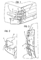
- Figure 1 is a first perspective view of a rear light unit of a motor vehicle embodying the device according to the invention,
- Figures 2 and 3 are further perspective views of the light unit of Figure 1, and
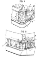
- Figures 4 and 5 show respective variants of the solution according to the invention.
- All five of the appended drawings show a rear corner part of the body of a motor vehicle, such as a car A, not illustrated in its entirety.
- One of the rear light units 1 of the motor vehicle is mounted at the corner.
- In general, it can be stated that the light unit 1 is mounted generally in a corner position between a respective side F and the rear panel P of the motor vehicle body.
- In all three embodiments of the invention illustrated in the drawings, an air intake formed in the side F immediately in front (in the normal direction of travel of the motor vehicle) of the light unit 1 is indicated 2.
- More precisely, this consists of an air intake of the type currently known as N.A.C.A. intake whose use is well known in the aeronautical field.
- The characteristic of the
intake 2 is that it is made so as to be sunken, that is, completely recessed relative to the outer surface of the side F of the motor vehicle body. In other words, the presence of the intakes 2 (two in number, one for each side of the motor vehicle) does not involve any increase in the main section of the motor vehicle. - When the vehicle is moving, the
intake 2 generates an air flow towards the light unit 1 at its widenedoutlet region 3 situated closely adjacent the light unit 1. - Figures 1 to 3 relate to a possible embodiment of the invention for cars of the Lancia Thema or Fiat Croma (both being trademarks) type. In this case, the light unit 1 is provided with an appendage 4 (made of transparent material which is identical - even as regards any division into horizontal strips of different colours - to the material constituting the so-called glass of the light unit) constituting a dihedral deflector situated in a corner position relative to the body.
- More precisely, the
deflector 4 has a generally dihedral configuration in which can be distinguished afirst limb 5 facing the outer surface of the side F (and coplanar therewith) and a second limb 6 facing the rear panel P and slightly spaced from the general plane of the rear panel P (as can better be seen in the view of Figure 3). - The
deflector 4 thus defines within it a flow duct connected at its upstream end to theoutlet region 3 of theair intake 2 and provided with outlet openings 7 which open onto that face of the light unit 1 which extends on the rear panel P of the body. - The function of the
deflector element 4, which is situated fluidodynamically downstream of theintake 2, is to convert the air flow induced by theintake 2 into a turbulent air flow which emerges from the openings 7 and flows across the surface of the light unit 1 which is on the rear panel P of the body. - When the vehicle is moving, the presence of this turbulent air flow in the space surrounding the light unit 1 means that dirt (dust, mud, etc.) which tends to be deposited on the rear panel P of the motor vehicle, particularly when the latter has a substantially flat conformation, is repelled from the region of the rear lights 1, which are thus kept substantially clean.
- Experimental tests conducted by the Applicants have shown that, in addition to the effect described, the presence of the
air intakes 2 at the rear ends of the sides of the motor vehicle also has the effect of increasing the longitudinal aerodynamic stability of the motor vehicle, making it less subject to slewing induced by any gusts of cross-wind. - The variants illustrated in Figures 4 and 5 differ from the solution shown in Figures 1 to 3 in that the air flow generated at the outlet of the
intake 2, instead of being deflected in a direction generally around the outer surface of the light unit 1, is deflected into a flow duct 8 which extends inwardly of the light unit (Figure 4), or at least of a portion thereof (Figure 5). - In both cases, therefore, the duct 8 extends from the
outlet end 3 of theair intake 2 towards the rear panel P, leaving at least one portion of the light unit 1 in a position outside the flow duct 8 (relative to the body of the motor vehicle). - In the embodiment illustrated in Figure 8, which relates to a rear light unit 1 of the type currently fitted to Fiat Panda cars, the duct 8 assumes the appearance of an actual slot which passes around the inside of the light unit 1 and opens onto the rear panel P through a
vertical slot 9. - In the embodiment of Figure 5, which relates to a rear light unit 1 of the type currently fitted to Autobianchi Y10 cars, the duct 8 passes around the inside of only part of the light unit 1 and opens onto the rear panel P through two holes 10 provided in that face of the light unit which is aligned with the rear panel P.
- In both cases, the
slot 9 or the holes 10 constitute nozzles which project the turbulent air flow, generated when the vehicle is moving, in a longitudinal direction relative to the motor vehicle. In this case also, the turbulent air flow spreads into the space surrounding the light unit 1 to prevent the deposition of dirt on the light unit.
Claims (9)
- an air intake (2) formed in the side (F) adjacent the light unit (1) and able, when the motor vehicle (A) is moving, to induce an air flow towards the light unit (1), and
- flow-conditioning means (4; 8) associated with the light unit (1) and situated fluidodynamically downstream of the air intake (2) so as to generate, from this air flow and in the space surrounding the light unit (1), a turbulent air flow which prevents the deposition of dirt on the light unit (1).
Applications Claiming Priority (2)
| Application Number | Priority Date | Filing Date | Title |
|---|---|---|---|
| IT6710987 | 1987-02-17 | ||
| IT8767109A IT1208852B (en) | 1987-02-17 | 1987-02-17 | DEVICE TO COUNTER SOIL PHENOMENA OF REAR LIGHTING GROUPS OF VEHICLES |
Publications (3)
| Publication Number | Publication Date |
|---|---|
| EP0279791A2 true EP0279791A2 (en) | 1988-08-24 |
| EP0279791A3 EP0279791A3 (en) | 1990-08-16 |
| EP0279791B1 EP0279791B1 (en) | 1993-10-13 |
Family
ID=11299647
Family Applications (1)
| Application Number | Title | Priority Date | Filing Date |
|---|---|---|---|
| EP88830053A Expired - Lifetime EP0279791B1 (en) | 1987-02-17 | 1988-02-12 | A device for preventing the rear light units of motor vehicles from becoming dirty |
Country Status (5)
| Country | Link |
|---|---|
| US (1) | US4838603A (en) |
| EP (1) | EP0279791B1 (en) |
| DE (1) | DE3884826T2 (en) |
| ES (1) | ES2045185T3 (en) |
| IT (1) | IT1208852B (en) |
Cited By (4)
| Publication number | Priority date | Publication date | Assignee | Title |
|---|---|---|---|---|
| WO2010026442A1 (en) * | 2008-09-04 | 2010-03-11 | Renault Trucks | Rear aerodynamic device for a vehicle and vehicle equipped with such a device |
| WO2012101203A1 (en) * | 2011-01-28 | 2012-08-02 | Bayerische Motoren Werke Aktiengesellschaft | Rear light for a motor vehicle |
| CN109383458A (en) * | 2017-08-14 | 2019-02-26 | 本田技研工业株式会社 | Vehicle |
| CN112537376A (en) * | 2019-09-20 | 2021-03-23 | 马自达汽车株式会社 | Vehicle body structure |
Families Citing this family (41)
| Publication number | Priority date | Publication date | Assignee | Title |
|---|---|---|---|---|
| USD323901S (en) | 1990-07-03 | 1992-02-11 | Aktiebolaget Volvo | Turn light for an automobile |
| US5409287A (en) * | 1992-05-01 | 1995-04-25 | Yamaha Hatsudoki Kabushiki Kaisha | Aerodynamic device |
| US5542737A (en) * | 1994-11-02 | 1996-08-06 | Madden; William R. | Air deflector for the rear of a vehicle |
| DE19602602A1 (en) * | 1996-01-25 | 1997-07-31 | Anton Dr Lechner | Device for reducing wind resistance of especially commercial vehicle |
| US6071000A (en) * | 1998-09-25 | 2000-06-06 | Valeo Sylvania, L.L.C. | Vehicle lamp with ram air vent |
| JP2000128049A (en) | 1998-10-27 | 2000-05-09 | Yamaha Motor Co Ltd | Body structure mounting structure for motorcycles |
| US6260911B1 (en) * | 2000-02-16 | 2001-07-17 | John H. Becker | Air duct for cooling rotating tires |
| US6561575B2 (en) * | 2001-08-23 | 2003-05-13 | Vacuum Breaker Mile Maker | Air channeler for reducing wind resistance and method of use |
| US6685256B1 (en) * | 2002-12-23 | 2004-02-03 | Carl L. Shermer | Trailer drag reduction system |
| DE102006019777A1 (en) * | 2006-04-28 | 2007-11-08 | Daimlerchrysler Ag | Motor vehicle rear end |
| DE102006033375A1 (en) | 2006-07-19 | 2008-01-31 | Dr.Ing.H.C. F. Porsche Ag | motor vehicle |
| US7695050B2 (en) * | 2006-11-01 | 2010-04-13 | Colin Neale | Vehicle having aerodynamic fan elements |
| DE102008003476B4 (en) | 2008-01-04 | 2021-08-26 | Volkswagen Ag | Vehicle with an air guiding element arranged on vehicle components |
| DE102008006103B4 (en) * | 2008-01-25 | 2017-12-28 | Dr. Ing. H.C. F. Porsche Aktiengesellschaft | motor vehicle |
| DE102010008332A1 (en) * | 2010-02-17 | 2011-08-18 | GM Global Technology Operations LLC, ( n. d. Ges. d. Staates Delaware ), Mich. | Vehicle having at least one flow influencing element with a spoiler edge and method for influencing an air resistance of a vehicle |
| DE102010027751B4 (en) * | 2010-04-14 | 2019-03-21 | Ford Global Technologies, Llc | motor vehicle |
| JP4962596B2 (en) * | 2010-05-17 | 2012-06-27 | 日産自動車株式会社 | Rear outlet structure for vehicles |
| DE102011003339A1 (en) | 2011-01-28 | 2012-08-02 | Bayerische Motoren Werke Aktiengesellschaft | Rear area for a motor vehicle |
| US9108229B2 (en) | 2011-06-17 | 2015-08-18 | The Procter & Gamble Company | Method and apparatus for particulate removal from moving paper webs |
| US8657998B2 (en) | 2011-06-17 | 2014-02-25 | The Procter & Gamble Company | Method and apparatus for particulate removal from moving paper webs |
| US8579482B2 (en) | 2011-07-12 | 2013-11-12 | Honda Motor Co., Ltd. | Debris protector for vehicle lamp assembly |
| US9126546B2 (en) * | 2011-10-13 | 2015-09-08 | Robert Bosch Gmbh | System and method to minimize contamination of a rear view camera lens |
| FR2982588B1 (en) * | 2011-11-10 | 2013-11-22 | Aircelle Sa | COMPOSITE PANEL WITH INTEGRATED SAMPLING ECOPE |
| DE102013216869B4 (en) * | 2013-08-23 | 2019-06-19 | Bayerische Motoren Werke Aktiengesellschaft | Cooling device for a headlight of a motor vehicle, in particular for a laser headlight |
| US9145085B2 (en) | 2013-08-27 | 2015-09-29 | Gregory D'Oliveira Henry | Reverse activated signaling circuit |
| JP2015141881A (en) * | 2014-01-30 | 2015-08-03 | 本田技研工業株式会社 | Vehicle rear structure |
| JP6167944B2 (en) | 2014-03-11 | 2017-07-26 | マツダ株式会社 | Rear structure of the vehicle |
| GB2528925B (en) | 2014-08-05 | 2018-05-30 | Jaguar Land Rover Ltd | Vehicle aerodynamic apparatus |
| US9409529B2 (en) | 2014-10-06 | 2016-08-09 | GM Global Technology Operations LLC | Camera system and vehicle |
| US9718506B1 (en) * | 2015-01-18 | 2017-08-01 | Jerry Alan Yeik | Vehicle propulsion system using wind |
| CA3035643C (en) * | 2016-09-05 | 2022-07-26 | Ogab Limited | An active drag-reduction system and a method of reducing drag experienced by a vehicle |
| DE112018000342T5 (en) | 2017-01-10 | 2019-10-02 | Ryan Leonard Joshua | Aerodynamic vehicle structures |
| JP6756899B2 (en) * | 2017-03-06 | 2020-09-16 | 株式会社ホンダアクセス | Aerodynamic parts for automobiles |
| KR102371066B1 (en) * | 2017-06-28 | 2022-03-07 | 현대자동차주식회사 | Air Passage type Wheel Deflector and Vehicle |
| DE102019004778A1 (en) * | 2019-07-09 | 2021-01-14 | Man Truck & Bus Se | Camera system with passive cleaning system for a motor vehicle |
| DE102021122884B4 (en) | 2021-09-03 | 2024-05-29 | Webasto SE | Roof module for forming a vehicle roof with a cleaning nozzle |
| US11634087B1 (en) * | 2021-09-16 | 2023-04-25 | Amazon Technologies, Inc. | Housing structure for a vehicle mounted optical device |
| DE102023005492A1 (en) | 2023-08-16 | 2025-02-20 | Motherson Innovations Company Limited | Camera arm with cleaning system for camera lens with air duct system |
| DE102023005493A1 (en) | 2023-08-16 | 2025-02-20 | Motherson Innovations Company Limited | Camera arm with cleaning device for camera lens with air duct system |
| DE102023121933A1 (en) * | 2023-08-16 | 2025-02-20 | Motherson Innovations Company Limited | Camera arm with cleaning device for camera lens with air duct system |
| DE102023005494A1 (en) | 2023-08-16 | 2025-02-20 | Motherson Innovations Company Limited | Camera arm with cleaning device for camera lens with air duct system |
Family Cites Families (9)
| Publication number | Priority date | Publication date | Assignee | Title |
|---|---|---|---|---|
| US3563598A (en) * | 1967-08-08 | 1971-02-16 | Daimler Benz Ag | Installation for the reduction of soiling of rear lights or the like at motor vehicle bodies |
| US3635517A (en) * | 1968-08-24 | 1972-01-18 | Daimler Benz Ag | Installation for reducing the soiling of rear lights in motor vehicle bodies |
| US3653709A (en) * | 1969-11-19 | 1972-04-04 | Darrell E Gravett | Air deflector |
| DE2162688C3 (en) * | 1971-12-17 | 1979-11-29 | Daimler-Benz Ag, 7000 Stuttgart | Device for preventing soiling of devices arranged on the rear of motor vehicles, in particular rear lights and license plates |
| US3768582A (en) * | 1972-02-14 | 1973-10-30 | Vel S Ford Sales Co Inc | Stabilizing device |
| US4159845A (en) * | 1978-03-22 | 1979-07-03 | Bratsberg Glenn N | Airstream deflector for motor vehicles |
| DE2844822C2 (en) * | 1978-10-14 | 1987-01-15 | Daimler-Benz Ag, 7000 Stuttgart | Diffuser for rear lights of vehicles, especially motor vehicles |
| US4378097A (en) * | 1980-11-24 | 1983-03-29 | The Boeing Company | High performance submerged air inlet |
| US4441752A (en) * | 1982-01-25 | 1984-04-10 | Richard P. Kughn | Automobile rear end construction |
-
1987
- 1987-02-17 IT IT8767109A patent/IT1208852B/en active
-
1988
- 1988-02-12 DE DE88830053T patent/DE3884826T2/en not_active Expired - Fee Related
- 1988-02-12 EP EP88830053A patent/EP0279791B1/en not_active Expired - Lifetime
- 1988-02-12 ES ES88830053T patent/ES2045185T3/en not_active Expired - Lifetime
- 1988-02-17 US US07/156,635 patent/US4838603A/en not_active Expired - Fee Related
Cited By (7)
| Publication number | Priority date | Publication date | Assignee | Title |
|---|---|---|---|---|
| WO2010026442A1 (en) * | 2008-09-04 | 2010-03-11 | Renault Trucks | Rear aerodynamic device for a vehicle and vehicle equipped with such a device |
| US8540304B2 (en) | 2008-09-04 | 2013-09-24 | Renault Trucks | Rear aerodynamic device for a vehicle and vehicle equipped with such a device |
| WO2012101203A1 (en) * | 2011-01-28 | 2012-08-02 | Bayerische Motoren Werke Aktiengesellschaft | Rear light for a motor vehicle |
| CN109383458A (en) * | 2017-08-14 | 2019-02-26 | 本田技研工业株式会社 | Vehicle |
| CN112537376A (en) * | 2019-09-20 | 2021-03-23 | 马自达汽车株式会社 | Vehicle body structure |
| EP3795459A1 (en) * | 2019-09-20 | 2021-03-24 | Mazda Motor Corporation | Vehicle structure, and vehicle |
| CN112537376B (en) * | 2019-09-20 | 2023-08-29 | 马自达汽车株式会社 | Vehicle body structure |
Also Published As
| Publication number | Publication date |
|---|---|
| ES2045185T3 (en) | 1994-01-16 |
| DE3884826D1 (en) | 1993-11-18 |
| US4838603A (en) | 1989-06-13 |
| EP0279791A3 (en) | 1990-08-16 |
| DE3884826T2 (en) | 1994-02-10 |
| EP0279791B1 (en) | 1993-10-13 |
| IT1208852B (en) | 1989-07-10 |
| IT8767109A0 (en) | 1987-02-17 |
Similar Documents
| Publication | Publication Date | Title |
|---|---|---|
| US4838603A (en) | Device for preventing the rear light units of motor vehicles from becoming dirty | |
| US5305011A (en) | Automotive display apparatus | |
| US5069538A (en) | Aerodynamic deflector for a rear view mirror with an integral side marker light | |
| US4441752A (en) | Automobile rear end construction | |
| US4979809A (en) | Air scoop mirror assembly | |
| US4962959A (en) | Rear window sunvisor | |
| JPS63263153A (en) | Aerodynamical deflector for wiper blade of front glass | |
| US5845960A (en) | Rear spoiler | |
| CA1197885A (en) | Rear side window demister | |
| JPH0630561Y2 (en) | Car rear spoiler | |
| JPS6111832B2 (en) | ||
| JP3855588B2 (en) | Duct outlet structure | |
| GB2304085A (en) | A vehicle bonnet and engine compartment air flow arrangement | |
| JPS6350230B2 (en) | ||
| KR960004716Y1 (en) | Adhesive strip for removing gaps in cars | |
| JPS5835551Y2 (en) | tail lamp device | |
| KR890006407Y1 (en) | Sun visor for car rearview mirror | |
| GB2175554A (en) | Cleaning device for vehicle rear-window | |
| JP2000318441A (en) | Defroster nozzle | |
| AU640362B2 (en) | Visor for rear window | |
| JPH0891123A (en) | Vehicle mirror device | |
| JPH061005U (en) | Vehicle bug spoiler | |
| JPH0110247Y2 (en) | ||
| JPH059238Y2 (en) | ||
| JPH07246960A (en) | Baffle plate device for truck |
Legal Events
| Date | Code | Title | Description |
|---|---|---|---|
| PUAI | Public reference made under article 153(3) epc to a published international application that has entered the european phase |
Free format text: ORIGINAL CODE: 0009012 |
|
| AK | Designated contracting states |
Kind code of ref document: A2 Designated state(s): DE ES FR GB SE |
|
| PUAL | Search report despatched |
Free format text: ORIGINAL CODE: 0009013 |
|
| AK | Designated contracting states |
Kind code of ref document: A3 Designated state(s): DE ES FR GB SE |
|
| 17P | Request for examination filed |
Effective date: 19900925 |
|
| 17Q | First examination report despatched |
Effective date: 19920312 |
|
| GRAA | (expected) grant |
Free format text: ORIGINAL CODE: 0009210 |
|
| AK | Designated contracting states |
Kind code of ref document: B1 Designated state(s): DE ES FR GB SE |
|
| REF | Corresponds to: |
Ref document number: 3884826 Country of ref document: DE Date of ref document: 19931118 |
|
| REG | Reference to a national code |
Ref country code: ES Ref legal event code: FG2A Ref document number: 2045185 Country of ref document: ES Kind code of ref document: T3 |
|
| PGFP | Annual fee paid to national office [announced via postgrant information from national office to epo] |
Ref country code: ES Payment date: 19940209 Year of fee payment: 7 |
|
| ET | Fr: translation filed | ||
| PLBE | No opposition filed within time limit |
Free format text: ORIGINAL CODE: 0009261 |
|
| STAA | Information on the status of an ep patent application or granted ep patent |
Free format text: STATUS: NO OPPOSITION FILED WITHIN TIME LIMIT |
|
| 26N | No opposition filed | ||
| EAL | Se: european patent in force in sweden |
Ref document number: 88830053.0 |
|
| PG25 | Lapsed in a contracting state [announced via postgrant information from national office to epo] |
Ref country code: ES Free format text: LAPSE BECAUSE OF NON-PAYMENT OF DUE FEES Effective date: 19950213 |
|
| PGFP | Annual fee paid to national office [announced via postgrant information from national office to epo] |
Ref country code: SE Payment date: 19970113 Year of fee payment: 10 |
|
| PGFP | Annual fee paid to national office [announced via postgrant information from national office to epo] |
Ref country code: GB Payment date: 19970122 Year of fee payment: 10 Ref country code: DE Payment date: 19970122 Year of fee payment: 10 |
|
| PGFP | Annual fee paid to national office [announced via postgrant information from national office to epo] |
Ref country code: FR Payment date: 19970228 Year of fee payment: 10 |
|
| PG25 | Lapsed in a contracting state [announced via postgrant information from national office to epo] |
Ref country code: GB Free format text: LAPSE BECAUSE OF NON-PAYMENT OF DUE FEES Effective date: 19980212 |
|
| PG25 | Lapsed in a contracting state [announced via postgrant information from national office to epo] |
Ref country code: SE Free format text: LAPSE BECAUSE OF NON-PAYMENT OF DUE FEES Effective date: 19980213 |
|
| PG25 | Lapsed in a contracting state [announced via postgrant information from national office to epo] |
Ref country code: FR Free format text: THE PATENT HAS BEEN ANNULLED BY A DECISION OF A NATIONAL AUTHORITY Effective date: 19980228 |
|
| GBPC | Gb: european patent ceased through non-payment of renewal fee |
Effective date: 19980212 |
|
| EUG | Se: european patent has lapsed |
Ref document number: 88830053.0 |
|
| PG25 | Lapsed in a contracting state [announced via postgrant information from national office to epo] |
Ref country code: DE Free format text: LAPSE BECAUSE OF NON-PAYMENT OF DUE FEES Effective date: 19981103 |
|
| REG | Reference to a national code |
Ref country code: FR Ref legal event code: ST |
|
| REG | Reference to a national code |
Ref country code: ES Ref legal event code: FD2A Effective date: 19990503 |