EP0278552B1 - Ceramic cylinders - Google Patents
Ceramic cylinders Download PDFInfo
- Publication number
- EP0278552B1 EP0278552B1 EP88200121A EP88200121A EP0278552B1 EP 0278552 B1 EP0278552 B1 EP 0278552B1 EP 88200121 A EP88200121 A EP 88200121A EP 88200121 A EP88200121 A EP 88200121A EP 0278552 B1 EP0278552 B1 EP 0278552B1
- Authority
- EP
- European Patent Office
- Prior art keywords
- cylinder
- ceramic
- slit
- portions
- cylinder according
- Prior art date
- Legal status (The legal status is an assumption and is not a legal conclusion. Google has not performed a legal analysis and makes no representation as to the accuracy of the status listed.)
- Expired
Links
- 239000000919 ceramic Substances 0.000 title claims description 13
- 238000002485 combustion reaction Methods 0.000 claims description 19
- 229910010293 ceramic material Inorganic materials 0.000 claims description 9
- 239000002184 metal Substances 0.000 claims description 9
- 229910052751 metal Inorganic materials 0.000 claims description 9
- 238000002347 injection Methods 0.000 claims description 5
- 239000007924 injection Substances 0.000 claims description 5
- 229910052581 Si3N4 Inorganic materials 0.000 claims description 3
- 229910000831 Steel Inorganic materials 0.000 claims description 3
- HQVNEWCFYHHQES-UHFFFAOYSA-N silicon nitride Chemical compound N12[Si]34N5[Si]62N3[Si]51N64 HQVNEWCFYHHQES-UHFFFAOYSA-N 0.000 claims description 3
- 125000006850 spacer group Chemical group 0.000 claims description 3
- 239000010959 steel Substances 0.000 claims description 3
- 230000035882 stress Effects 0.000 description 13
- 239000007789 gas Substances 0.000 description 7
- 239000000446 fuel Substances 0.000 description 6
- 230000004323 axial length Effects 0.000 description 3
- 230000006835 compression Effects 0.000 description 3
- 238000007906 compression Methods 0.000 description 3
- 239000000463 material Substances 0.000 description 3
- 230000000694 effects Effects 0.000 description 2
- 230000008646 thermal stress Effects 0.000 description 2
- 229920002972 Acrylic fiber Polymers 0.000 description 1
- 229910001018 Cast iron Inorganic materials 0.000 description 1
- -1 Syalon (trade mark) Chemical compound 0.000 description 1
- 238000006243 chemical reaction Methods 0.000 description 1
- 239000000567 combustion gas Substances 0.000 description 1
- 238000000227 grinding Methods 0.000 description 1
- 238000005461 lubrication Methods 0.000 description 1
- 238000004519 manufacturing process Methods 0.000 description 1
- 238000000034 method Methods 0.000 description 1
- 230000001473 noxious effect Effects 0.000 description 1
- 239000004033 plastic Substances 0.000 description 1
- 229920003023 plastic Polymers 0.000 description 1
- HBMJWWWQQXIZIP-UHFFFAOYSA-N silicon carbide Chemical compound [Si+]#[C-] HBMJWWWQQXIZIP-UHFFFAOYSA-N 0.000 description 1
- 229910010271 silicon carbide Inorganic materials 0.000 description 1
- 230000002277 temperature effect Effects 0.000 description 1
Images

Classifications
-
- F—MECHANICAL ENGINEERING; LIGHTING; HEATING; WEAPONS; BLASTING
- F02—COMBUSTION ENGINES; HOT-GAS OR COMBUSTION-PRODUCT ENGINE PLANTS
- F02F—CYLINDERS, PISTONS OR CASINGS, FOR COMBUSTION ENGINES; ARRANGEMENTS OF SEALINGS IN COMBUSTION ENGINES
- F02F7/00—Casings, e.g. crankcases
- F02F7/0085—Materials for constructing engines or their parts
- F02F7/0087—Ceramic materials
-
- F—MECHANICAL ENGINEERING; LIGHTING; HEATING; WEAPONS; BLASTING
- F02—COMBUSTION ENGINES; HOT-GAS OR COMBUSTION-PRODUCT ENGINE PLANTS
- F02F—CYLINDERS, PISTONS OR CASINGS, FOR COMBUSTION ENGINES; ARRANGEMENTS OF SEALINGS IN COMBUSTION ENGINES
- F02F1/00—Cylinders; Cylinder heads
- F02F1/18—Other cylinders
- F02F1/20—Other cylinders characterised by constructional features providing for lubrication
-
- F—MECHANICAL ENGINEERING; LIGHTING; HEATING; WEAPONS; BLASTING
- F02—COMBUSTION ENGINES; HOT-GAS OR COMBUSTION-PRODUCT ENGINE PLANTS
- F02B—INTERNAL-COMBUSTION PISTON ENGINES; COMBUSTION ENGINES IN GENERAL
- F02B3/00—Engines characterised by air compression and subsequent fuel addition
- F02B3/06—Engines characterised by air compression and subsequent fuel addition with compression ignition
-
- F—MECHANICAL ENGINEERING; LIGHTING; HEATING; WEAPONS; BLASTING
- F02—COMBUSTION ENGINES; HOT-GAS OR COMBUSTION-PRODUCT ENGINE PLANTS
- F02F—CYLINDERS, PISTONS OR CASINGS, FOR COMBUSTION ENGINES; ARRANGEMENTS OF SEALINGS IN COMBUSTION ENGINES
- F02F1/00—Cylinders; Cylinder heads
- F02F2001/008—Stress problems, especially related to thermal stress
Definitions
- the present invention relates to cylinders for internal combustion engines and particularly to such cylinders manufactured from ceramic materials.
- Ceramic material It is desirable to be able to manufacture some components of internal combustion engines, especially diesels, from ceramic material.
- Such components include the pistons and cylinders of cylinder liners which may be subject to the action of hot combustion gases and abrasive fuels. It is generally considered that the ability to use ceramic materials for some components will allow higher temperatures to be employed in the combustion chamber region, such higher temperatures being advantageous in lowering noxious emissions from the engine.
- Another advantage of some ceramic materials is the ability to operate without the need for external lubrication at high temperatures.
- the cylinder of an internal combustion engine has to withstand high mechanical stresses due to the gas pressures generated by the burning fuel charge at the moment of ignition and also very high thermal stresses due to temperature fluctuations over short time periods.
- Ceramic materials are generally better at withstanding compressive stresses than tensile stresses.
- a problem with this is that due to the thermal and mechanical stresses involved and to differences in the coefficient of thermal expansion between the metal sleeve and the ceramic piece the ceramic liner invariably works loose.
- a ceramic cylinder for an internal combustion engine comprises at least two portions including at least one main cylinder portion and at least one combustion region portion the at least two portions being contained within a metal housing and wherein the at least one combustion region portion has a generally axially directed slit therein, the slit passing through the whole thickness of the ceramic material.
- the portion of liner in the combustion region has to withstand the highest thermal and mechanical stresses.
- the slit allows this portion to deform elastically in compression and to accommodate any expansion effects in the supporting metal housing without loosening.
- the metal housing may comprise a metal sleeve.
- features such as injection ports etc. may be sited on the line of the slit thereby minimising any stress raising tendencies such features may otherwise promote.
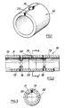
- a complete cylinder liner assembly is denoted at 10.
- the assembly comprises a steel outer sleeve 11, two outer main cylinder portions 12, 13 and a combustion region portion 14.
- One outer portion 12 includes exhaust ports 15 which pass through co-operating ports 16 in the sleeve 11 whilst the other outer portion 13 includes inlet ports 17 which similarly co-operate with ports 18 in the sleeve 11.
- the combustion region portion 14 includes a fuel injection port 19 which is situated in an axial slit 20 which passes through the wall thickness of the portion 14.
- the portions 12, 13 and 14 are made from silicon nitride material produced by the reaction bonding process.
- Other materials may of course by used including, for example, sintered silicon nitride, Syalon (trade mark), silicon carbide, etc.
- the portion 14 is compressed such that the opposite faces of the slit 20 approach each other and is permanently elastically deformed whilst in the sleeve 11 even allowing for temperature effects. Siting of the injection port 19 in the slit 20 prevents the port from becoming a significant stress-raising feature. Because the portion 14 is permanently in compression harmful tensile forces are never able to develop whatever the temperature and gas loading conditions.
- the ceramic liner portions are assembled into the sleeve 11 and any steps present at the interfaces between the portions are removed by a grinding operation which results in the cylinder achieving the desired finished bore dimension. Any slight step which may be generated during running may be accommodated by appropriate tapers or chamfers on the associated pistons (not shown) and piston rings (not shown) if used.
- heat degradable spacers may be positioned between the cylinder portions. Plastics materials such as acrylic plastic, for example, may be used. Such shims or spacers burn away in operation to leave the desired axial spacing of the ceramic cylinder portions. The ash produced is ejected via the exhaust ports.
- the portion 14 may be of relatively short axial length since the rate of gas pressure and temperature reduction along the cylinder axial length is very high.
- the portions 12 and 13 are fully able to accommodate the gas pressure and temperature variations without the need for an axial slit since the average levels of pressure and temperature are much lower. Furthermore, there is no extra gas leakage due to the slit since the effect of the slit is only to add a slight additional volume to the combustion chamber, the slit being effectively sealed at the interfaces between the three portions.
- Figures 4 and 5 show a cylinder in an engine the cylinder comprising a cast iron support 40 formed by the engine block, a main cylinder portion 41 and a combustion region portion 42.
- the combustion region portion 41 comprises a slit 43 in the axial direction.
- Fuel injection means (not shown) are included in the cylinder head 44.
- a piston 45 traverses the joint interface 46 between the two portions 41 and 42.
Landscapes
- Engineering & Computer Science (AREA)
- Chemical & Material Sciences (AREA)
- Combustion & Propulsion (AREA)
- Mechanical Engineering (AREA)
- General Engineering & Computer Science (AREA)
- Ceramic Engineering (AREA)
- Cylinder Crankcases Of Internal Combustion Engines (AREA)
- Combustion Methods Of Internal-Combustion Engines (AREA)
- Fuel-Injection Apparatus (AREA)
Description
- The present invention relates to cylinders for internal combustion engines and particularly to such cylinders manufactured from ceramic materials.
- It is desirable to be able to manufacture some components of internal combustion engines, especially diesels, from ceramic material. Such components include the pistons and cylinders of cylinder liners which may be subject to the action of hot combustion gases and abrasive fuels. It is generally considered that the ability to use ceramic materials for some components will allow higher temperatures to be employed in the combustion chamber region, such higher temperatures being advantageous in lowering noxious emissions from the engine.
- Another advantage of some ceramic materials is the ability to operate without the need for external lubrication at high temperatures.
- The cylinder of an internal combustion engine has to withstand high mechanical stresses due to the gas pressures generated by the burning fuel charge at the moment of ignition and also very high thermal stresses due to temperature fluctuations over short time periods.
- Not only are such stresses continuously varying with time in the region of the cylinder near to the combustion chamber but they are also varying depending on position in all other parts of the cylinder. There is, for example, a stress gradient due to gas pressure variations throughout the working cycle and also a thermal stress gradient due to temperature variation from top to bottom of the cylinder.
- Such stress variations especially when combined with physical discontinuities in ceramic cylinder components can lead to catastrophic failures. For example, in the case of a diesel engine having horizontally opposed pistons where a fuel injector port is sited in the centre of the axial length of the cylinder, it has been found that failure of the cylinder occurs by cracks emanating from the fuel injector port which acts as a stress concentrator.
- Ceramic materials are generally better at withstanding compressive stresses than tensile stresses. In order to minimise the tensile stresses imposed upon the ceramic material of the cylinder it has been proposed to fit the complete ceramic cylinder inside a metal supporting sleeve by interference or shrink fitting. A problem with this is that due to the thermal and mechanical stresses involved and to differences in the coefficient of thermal expansion between the metal sleeve and the ceramic piece the ceramic liner invariably works loose.
- According to the present invention a ceramic cylinder for an internal combustion engine comprises at least two portions including at least one main cylinder portion and at least one combustion region portion the at least two portions being contained within a metal housing and wherein the at least one combustion region portion has a generally axially directed slit therein, the slit passing through the whole thickness of the ceramic material.
- The portion of liner in the combustion region has to withstand the highest thermal and mechanical stresses. The slit allows this portion to deform elastically in compression and to accommodate any expansion effects in the supporting metal housing without loosening.
- The metal housing may comprise a metal sleeve.
- Where necessitated by the specific engine design, features such as injection ports etc. may be sited on the line of the slit thereby minimising any stress raising tendencies such features may otherwise promote.
- Stresses due to gas pressure within the cylinder are borne in compression since the combustion chamber portion of the cylinder liner is able to be fully supported by the metal housing without the generation of significant tensile stresses.
- In order that the invention may be more fully understood examples will now be described by way of illustration only with reference to the accompanying drawings, of which:
- Figure 1 shows a schematic perspective view of a combustion chamber region portion of a ceramic cylinder liner according to the present invention for an opposed-piston 2-stroke diesel engine;
- Figure 2 shows a section in elevation of a ceramic cylinder liner assembly according to the present invention;
- Figure 3 shows a section through the line AA¹ of the cylinder liner of Figure 2 looking in the direction of the arrows;
- Figure 4 shows a section in elevation of a schematic representation of another type of reciprocating piston diesel engine having a cylinder according to the present invention; and
- Figure 5 which shows a section through the line BB¹ of Figure 4 looking in the direction of the arrows.
- Referring now to Figures 1 to 3 and where the same features are denoted by common reference numerals.
- A complete cylinder liner assembly is denoted at 10. The assembly comprises a steel
outer sleeve 11, two outermain cylinder portions combustion region portion 14. Oneouter portion 12 includesexhaust ports 15 which pass throughco-operating ports 16 in thesleeve 11 whilst the otherouter portion 13 includes inlet ports 17 which similarly co-operate withports 18 in thesleeve 11. Thecombustion region portion 14 includes afuel injection port 19 which is situated in anaxial slit 20 which passes through the wall thickness of theportion 14. - The
portions - The
portion 14 is compressed such that the opposite faces of theslit 20 approach each other and is permanently elastically deformed whilst in thesleeve 11 even allowing for temperature effects. Siting of theinjection port 19 in theslit 20 prevents the port from becoming a significant stress-raising feature. Because theportion 14 is permanently in compression harmful tensile forces are never able to develop whatever the temperature and gas loading conditions. - The ceramic liner portions are assembled into the
sleeve 11 and any steps present at the interfaces between the portions are removed by a grinding operation which results in the cylinder achieving the desired finished bore dimension. Any slight step which may be generated during running may be accommodated by appropriate tapers or chamfers on the associated pistons (not shown) and piston rings (not shown) if used. To allow for inevitable variations in differential expansion between the steel sleeve and ceramic cylinder portions, heat degradable spacers may be positioned between the cylinder portions. Plastics materials such as acrylic plastic, for example, may be used. Such shims or spacers burn away in operation to leave the desired axial spacing of the ceramic cylinder portions. The ash produced is ejected via the exhaust ports. - The
portion 14 may be of relatively short axial length since the rate of gas pressure and temperature reduction along the cylinder axial length is very high. Theportions - Figures 4 and 5 show a cylinder in an engine the cylinder comprising a
cast iron support 40 formed by the engine block, amain cylinder portion 41 and acombustion region portion 42. Thecombustion region portion 41 comprises aslit 43 in the axial direction. Fuel injection means (not shown) are included in the cylinder head 44. Apiston 45 traverses the joint interface 46 between the twoportions
Claims (6)
- A ceramic cylinder for an internal combustion engine the cylinder comprising at least two portions including at least one main cylinder portion (12, 13) (41) and at least one combustion region portion (14) (42) the at least two portions being contained within a metal housing (11) (40) and characterised in that the at least one combustion region portion has a generally axially directed slit (20) (43) therein, the slit passing through the whole thickness of the ceramic material.
- A cylinder according to Claim 1 characterised by further having features such as injection ports (19) sited on the line of the slit.
- A cylinder according to either Claim 1 or Claim 2 characterised in that the ceramic cylinder portions are initially spaced from each other by heat degradable spacers.
- A cylinder according to any one preceding claim characterised in that the ceramic material comprises silicon nitride.
- A cylinder according to any one preceding claim characterised in that housing comprises a metal sleeve (11).
- A cylinder according to Claim 5 characterised in that the sleeve is made of steel.
Applications Claiming Priority (2)
| Application Number | Priority Date | Filing Date | Title |
|---|---|---|---|
| GB8703330 | 1987-02-13 | ||
| GB878703330A GB8703330D0 (en) | 1987-02-13 | 1987-02-13 | Ceramic cylinders |
Publications (3)
| Publication Number | Publication Date |
|---|---|
| EP0278552A2 EP0278552A2 (en) | 1988-08-17 |
| EP0278552A3 EP0278552A3 (en) | 1989-06-07 |
| EP0278552B1 true EP0278552B1 (en) | 1992-02-26 |
Family
ID=10612244
Family Applications (1)
| Application Number | Title | Priority Date | Filing Date |
|---|---|---|---|
| EP88200121A Expired EP0278552B1 (en) | 1987-02-13 | 1988-01-26 | Ceramic cylinders |
Country Status (4)
| Country | Link |
|---|---|
| US (1) | US4841927A (en) |
| EP (1) | EP0278552B1 (en) |
| DE (1) | DE3868519D1 (en) |
| GB (2) | GB8703330D0 (en) |
Families Citing this family (9)
| Publication number | Priority date | Publication date | Assignee | Title |
|---|---|---|---|---|
| CA2115573C (en) * | 1991-09-12 | 1999-08-03 | Maxime Paquette | Internal combustion engine having opposed pistons |
| US5404793A (en) * | 1993-06-03 | 1995-04-11 | Myers; Blake | Ceramic tile expansion engine housing |
| US5392596A (en) * | 1993-12-21 | 1995-02-28 | Solar Turbines Incorporated | Combustor assembly construction |
| US6213064B1 (en) * | 1998-06-16 | 2001-04-10 | Wing Ping Geung | Double throw engine |
| JP3789691B2 (en) * | 1999-09-14 | 2006-06-28 | 三洋電機株式会社 | High pressure compressor compressor |
| US7469626B2 (en) * | 2005-07-29 | 2008-12-30 | Honeywell International, Inc. | Split ceramic bore liner, rotor body having a split ceramic bore liner and method of lining a rotor bore with a split ceramic bore liner |
| CA2710280A1 (en) * | 2007-12-21 | 2009-07-09 | Green Partners Technology Holdings Gmbh | Gas turbine systems and methods employing a vaporizable liquid delivery device |
| BRPI0821738A2 (en) * | 2007-12-21 | 2015-06-16 | Green Partners Technology Gmbh | Open and closed and semi-closed energy gas turbine and expansion turbine and closed cycle piston compressor gas turbine system, turbocharger and operating gas compression turbine, short cycle gas turbine power production methods in turbocharger and engine system operation |
| US12595758B2 (en) * | 2022-08-03 | 2026-04-07 | Creed Engines Llc | Optimal efficiency internal combustion engine |
Family Cites Families (4)
| Publication number | Priority date | Publication date | Assignee | Title |
|---|---|---|---|---|
| GB541902A (en) * | 1939-03-20 | 1941-12-17 | Thompson Prod Inc | Improvements in or relating to liner sleeves, method of making the same and method of lining members having cylindrical bores |
| GB566917A (en) * | 1941-09-20 | 1945-01-19 | Sulzer Ag | Improvements in or relating to internal combustion engines of the opposed piston type |
| JPS5675940A (en) * | 1979-11-21 | 1981-06-23 | Toshiba Corp | Cylinder for internal combustion engine |
| JPS5978980A (en) * | 1982-10-22 | 1984-05-08 | 臼井国際産業株式会社 | Metal substrate surface and ceramic joint mechanism |
-
1987
- 1987-02-13 GB GB878703330A patent/GB8703330D0/en active Pending
-
1988
- 1988-01-25 GB GB8801615A patent/GB2205364B/en not_active Expired - Fee Related
- 1988-01-26 EP EP88200121A patent/EP0278552B1/en not_active Expired
- 1988-01-26 DE DE8888200121T patent/DE3868519D1/en not_active Expired - Fee Related
- 1988-02-10 US US07/154,306 patent/US4841927A/en not_active Expired - Fee Related
Also Published As
| Publication number | Publication date |
|---|---|
| GB8801615D0 (en) | 1988-02-24 |
| EP0278552A3 (en) | 1989-06-07 |
| GB2205364B (en) | 1990-06-20 |
| GB8703330D0 (en) | 1987-03-18 |
| GB2205364A (en) | 1988-12-07 |
| EP0278552A2 (en) | 1988-08-17 |
| DE3868519D1 (en) | 1992-04-02 |
| US4841927A (en) | 1989-06-27 |
Similar Documents
| Publication | Publication Date | Title |
|---|---|---|
| KR101617915B1 (en) | Pre-chamber arrangement for a combustion engine | |
| EP2205840B1 (en) | Prechamber arrangement of a combustion engine | |
| US6026568A (en) | High efficiency low-pollution engine | |
| CA1246346A (en) | Combustion system | |
| EP0278552B1 (en) | Ceramic cylinders | |
| US5033426A (en) | Radial combustion seal | |
| JPS59131748A (en) | Piston for internal combustion engine | |
| US3959974A (en) | Internal combustion engine | |
| US7975601B2 (en) | Engine cylinder liner | |
| US5295462A (en) | Coin insert for the firing deck in an internal combustion engine | |
| US4508066A (en) | Ceramic head for internal combustion engine | |
| JPH0357298B2 (en) | ||
| CA1324543C (en) | Multipart ceramic cylinder head | |
| CA1285837C (en) | Steam purge of a piston/cylinder gap in a diesel engine | |
| JP2021085408A (en) | Piston ring for large engine, and large engine | |
| EP0167528B1 (en) | Ceramic head for internal combustion engine | |
| EP0780554B1 (en) | Piston structure with heat insulated combustion chamber | |
| JPH0259295B2 (en) | ||
| WO2026072727A1 (en) | Piston cylinder system and method | |
| JPH0754580Y2 (en) | Sub chamber structure of engine | |
| Timoney et al. | Hoop stress effects on thick ceramic cylinders for Diesel engines | |
| US10087878B2 (en) | Cylinder head cover with integral sleeve | |
| JPH029066Y2 (en) | ||
| JPS60145445A (en) | Cylinder head structure for engine | |
| JPS60190649A (en) | Aluminum piston structure |
Legal Events
| Date | Code | Title | Description |
|---|---|---|---|
| PUAI | Public reference made under article 153(3) epc to a published international application that has entered the european phase |
Free format text: ORIGINAL CODE: 0009012 |
|
| AK | Designated contracting states |
Kind code of ref document: A2 Designated state(s): DE FR IT |
|
| 17P | Request for examination filed |
Effective date: 19881122 |
|
| PUAL | Search report despatched |
Free format text: ORIGINAL CODE: 0009013 |
|
| AK | Designated contracting states |
Kind code of ref document: A3 Designated state(s): DE FR IT |
|
| 17Q | First examination report despatched |
Effective date: 19910429 |
|
| GRAA | (expected) grant |
Free format text: ORIGINAL CODE: 0009210 |
|
| ITF | It: translation for a ep patent filed | ||
| AK | Designated contracting states |
Kind code of ref document: B1 Designated state(s): DE FR IT |
|
| REF | Corresponds to: |
Ref document number: 3868519 Country of ref document: DE Date of ref document: 19920402 |
|
| ET | Fr: translation filed | ||
| PLBE | No opposition filed within time limit |
Free format text: ORIGINAL CODE: 0009261 |
|
| STAA | Information on the status of an ep patent application or granted ep patent |
Free format text: STATUS: NO OPPOSITION FILED WITHIN TIME LIMIT |
|
| 26N | No opposition filed | ||
| PG25 | Lapsed in a contracting state [announced via postgrant information from national office to epo] |
Ref country code: FR Effective date: 19930930 |
|
| PG25 | Lapsed in a contracting state [announced via postgrant information from national office to epo] |
Ref country code: DE Effective date: 19931001 |
|
| REG | Reference to a national code |
Ref country code: FR Ref legal event code: ST |
|
| PG25 | Lapsed in a contracting state [announced via postgrant information from national office to epo] |
Ref country code: IT Free format text: LAPSE BECAUSE OF NON-PAYMENT OF DUE FEES;WARNING: LAPSES OF ITALIAN PATENTS WITH EFFECTIVE DATE BEFORE 2007 MAY HAVE OCCURRED AT ANY TIME BEFORE 2007. THE CORRECT EFFECTIVE DATE MAY BE DIFFERENT FROM THE ONE RECORDED. Effective date: 20050126 |