EP0277720A2 - Schnellabtastspektralphotometer mit ununterbrochen drehendem Gitter - Google Patents
Schnellabtastspektralphotometer mit ununterbrochen drehendem Gitter Download PDFInfo
- Publication number
- EP0277720A2 EP0277720A2 EP88300390A EP88300390A EP0277720A2 EP 0277720 A2 EP0277720 A2 EP 0277720A2 EP 88300390 A EP88300390 A EP 88300390A EP 88300390 A EP88300390 A EP 88300390A EP 0277720 A2 EP0277720 A2 EP 0277720A2
- Authority
- EP
- European Patent Office
- Prior art keywords
- grating
- radiation
- spectrophotometer
- detector
- shaft
- Prior art date
- Legal status (The legal status is an assumption and is not a legal conclusion. Google has not performed a legal analysis and makes no representation as to the accuracy of the status listed.)
- Withdrawn
Links
- 230000003287 optical effect Effects 0.000 claims abstract description 39
- 238000005070 sampling Methods 0.000 claims abstract description 15
- 230000001133 acceleration Effects 0.000 claims abstract description 6
- 230000005855 radiation Effects 0.000 claims description 28
- 238000001228 spectrum Methods 0.000 claims description 19
- 238000012545 processing Methods 0.000 claims description 11
- 230000003595 spectral effect Effects 0.000 claims description 11
- 230000004044 response Effects 0.000 claims description 7
- 230000001360 synchronised effect Effects 0.000 claims 2
- 230000000977 initiatory effect Effects 0.000 claims 1
- 230000006870 function Effects 0.000 abstract description 7
- 238000005259 measurement Methods 0.000 abstract description 5
- 238000012546 transfer Methods 0.000 abstract description 3
- 238000010183 spectrum analysis Methods 0.000 abstract 1
- 230000000694 effects Effects 0.000 description 7
- 230000000007 visual effect Effects 0.000 description 6
- 230000008901 benefit Effects 0.000 description 5
- 238000002835 absorbance Methods 0.000 description 3
- 238000003491 array Methods 0.000 description 3
- 238000012937 correction Methods 0.000 description 3
- 230000001419 dependent effect Effects 0.000 description 3
- 230000007246 mechanism Effects 0.000 description 3
- 238000004611 spectroscopical analysis Methods 0.000 description 3
- 238000000870 ultraviolet spectroscopy Methods 0.000 description 3
- 238000004566 IR spectroscopy Methods 0.000 description 1
- XUIMIQQOPSSXEZ-UHFFFAOYSA-N Silicon Chemical compound [Si] XUIMIQQOPSSXEZ-UHFFFAOYSA-N 0.000 description 1
- 238000010521 absorption reaction Methods 0.000 description 1
- 238000000862 absorption spectrum Methods 0.000 description 1
- 238000007743 anodising Methods 0.000 description 1
- 230000006399 behavior Effects 0.000 description 1
- 238000004364 calculation method Methods 0.000 description 1
- 239000011248 coating agent Substances 0.000 description 1
- 238000000576 coating method Methods 0.000 description 1
- 238000013500 data storage Methods 0.000 description 1
- 230000003247 decreasing effect Effects 0.000 description 1
- 238000010586 diagram Methods 0.000 description 1
- 238000006073 displacement reaction Methods 0.000 description 1
- 230000009977 dual effect Effects 0.000 description 1
- 238000000426 electronic spectroscopy Methods 0.000 description 1
- 238000013213 extrapolation Methods 0.000 description 1
- 238000004817 gas chromatography Methods 0.000 description 1
- 238000004128 high performance liquid chromatography Methods 0.000 description 1
- 230000010365 information processing Effects 0.000 description 1
- 238000004811 liquid chromatography Methods 0.000 description 1
- 230000007774 longterm Effects 0.000 description 1
- 238000004519 manufacturing process Methods 0.000 description 1
- 239000000463 material Substances 0.000 description 1
- 238000000034 method Methods 0.000 description 1
- 238000012986 modification Methods 0.000 description 1
- 230000004048 modification Effects 0.000 description 1
- 230000008569 process Effects 0.000 description 1
- 238000013214 routine measurement Methods 0.000 description 1
- 230000035945 sensitivity Effects 0.000 description 1
- 229910052710 silicon Inorganic materials 0.000 description 1
- 239000010703 silicon Substances 0.000 description 1
- 238000002798 spectrophotometry method Methods 0.000 description 1
- GYTROFMCUJZKNA-UHFFFAOYSA-N triethyl triethoxysilyl silicate Chemical compound CCO[Si](OCC)(OCC)O[Si](OCC)(OCC)OCC GYTROFMCUJZKNA-UHFFFAOYSA-N 0.000 description 1
- 238000002211 ultraviolet spectrum Methods 0.000 description 1
- 238000012795 verification Methods 0.000 description 1
Images

Classifications
-
- G—PHYSICS
- G01—MEASURING; TESTING
- G01J—MEASUREMENT OF INTENSITY, VELOCITY, SPECTRAL CONTENT, POLARISATION, PHASE OR PULSE CHARACTERISTICS OF INFRARED, VISIBLE OR ULTRAVIOLET LIGHT; COLORIMETRY; RADIATION PYROMETRY
- G01J3/00—Spectrometry; Spectrophotometry; Monochromators; Measuring colours
- G01J3/02—Details
- G01J3/06—Scanning arrangements arrangements for order-selection
-
- G—PHYSICS
- G01—MEASURING; TESTING
- G01J—MEASUREMENT OF INTENSITY, VELOCITY, SPECTRAL CONTENT, POLARISATION, PHASE OR PULSE CHARACTERISTICS OF INFRARED, VISIBLE OR ULTRAVIOLET LIGHT; COLORIMETRY; RADIATION PYROMETRY
- G01J3/00—Spectrometry; Spectrophotometry; Monochromators; Measuring colours
- G01J3/28—Investigating the spectrum
- G01J3/2889—Rapid scan spectrometers; Time resolved spectrometry
-
- G—PHYSICS
- G01—MEASURING; TESTING
- G01J—MEASUREMENT OF INTENSITY, VELOCITY, SPECTRAL CONTENT, POLARISATION, PHASE OR PULSE CHARACTERISTICS OF INFRARED, VISIBLE OR ULTRAVIOLET LIGHT; COLORIMETRY; RADIATION PYROMETRY
- G01J1/00—Photometry, e.g. photographic exposure meter
- G01J1/42—Photometry, e.g. photographic exposure meter using electric radiation detectors
- G01J1/44—Electric circuits
- G01J2001/444—Compensating; Calibrating, e.g. dark current, temperature drift, noise reduction or baseline correction; Adjusting
-
- G—PHYSICS
- G01—MEASURING; TESTING
- G01J—MEASUREMENT OF INTENSITY, VELOCITY, SPECTRAL CONTENT, POLARISATION, PHASE OR PULSE CHARACTERISTICS OF INFRARED, VISIBLE OR ULTRAVIOLET LIGHT; COLORIMETRY; RADIATION PYROMETRY
- G01J3/00—Spectrometry; Spectrophotometry; Monochromators; Measuring colours
- G01J3/02—Details
- G01J3/06—Scanning arrangements arrangements for order-selection
- G01J2003/062—Scanning arrangements arrangements for order-selection motor-driven
-
- G—PHYSICS
- G01—MEASURING; TESTING
- G01J—MEASUREMENT OF INTENSITY, VELOCITY, SPECTRAL CONTENT, POLARISATION, PHASE OR PULSE CHARACTERISTICS OF INFRARED, VISIBLE OR ULTRAVIOLET LIGHT; COLORIMETRY; RADIATION PYROMETRY
- G01J3/00—Spectrometry; Spectrophotometry; Monochromators; Measuring colours
- G01J3/02—Details
- G01J3/06—Scanning arrangements arrangements for order-selection
- G01J2003/066—Microprocessor control of functions, e.g. slit, scan, bandwidth during scan
-
- G—PHYSICS
- G01—MEASURING; TESTING
- G01J—MEASUREMENT OF INTENSITY, VELOCITY, SPECTRAL CONTENT, POLARISATION, PHASE OR PULSE CHARACTERISTICS OF INFRARED, VISIBLE OR ULTRAVIOLET LIGHT; COLORIMETRY; RADIATION PYROMETRY
- G01J3/00—Spectrometry; Spectrophotometry; Monochromators; Measuring colours
- G01J3/28—Investigating the spectrum
- G01J2003/2866—Markers; Calibrating of scan
-
- G—PHYSICS
- G01—MEASURING; TESTING
- G01J—MEASUREMENT OF INTENSITY, VELOCITY, SPECTRAL CONTENT, POLARISATION, PHASE OR PULSE CHARACTERISTICS OF INFRARED, VISIBLE OR ULTRAVIOLET LIGHT; COLORIMETRY; RADIATION PYROMETRY
- G01J3/00—Spectrometry; Spectrophotometry; Monochromators; Measuring colours
- G01J3/12—Generating the spectrum; Monochromators
- G01J3/18—Generating the spectrum; Monochromators using diffraction elements, e.g. grating
- G01J3/1838—Holographic gratings
Definitions
- the field of the invention pertains to spectrophotometry and, in particular, to rapid-scan spectrophotometers and the speed with which such instruments can scan the relevant spectra.
- the entrance and exit slits are located on either side of the optical grating.
- a simple elliptically concave mirror is used as a collimating and focusing mirror intersecting and directing the light from an ultraviolet or visual light generator for a UV/VIS spectrophotometer.
- the light beams entering the monochromator strike the left side of the mirror, are collimated and reflected to the grating.
- the diffracted radiation goes to the right half of the same mirror and is focused on the exit slit.
- the wavelength is selected by simple pivoting of the grating about the monochromator axis. The angle between the incident and diffracted rays remains constant. Either a manual or motor driven sine bar drive produces a direct wavelength readout on a linear scale.
- the grating Since the useful range in UV/VIS spectroscopy lies typically within a few degrees about the grating optical axis, the grating is rotated back and forth over this range to scan the region of interest. Mechanical scanning of the desired spectrum is achieved through a device such as a stepping motor. The information from a shaft encoder thereattached is used to translate the angular position of the grating into a wavelength.
- Spectrophotometers that rely upon such electromechanically reversing arrangements for the grating cannot truly be considered rapid scanning, because they typically scan about 400 to 2400 nm per minute. The arrangement cannot be increased in speed because of the mechanical cam shaft follower drive and the need to determine the grating position accurately.
- High-throughput spectroscopy can also be accomplished with a fast mechanical scanner with all reflective optics. Scanning is achieved by vibrating a low-inertia grating or mirror as disclosed in U.S. Pat. 4,225,233 and the paper by J. Stoijek and Z. Uziel, Pol. J. Chem., 53 , 1619 (1979).
- the mirror or grating (depending on the optical configuration) is mounted directly on the output shaft of a galvanometer type optical scanner, where the position is a function of the applied electric current.
- a commercial device based on U.S. Pat. 4,070,111 is available presently with a vibrating grating.
- the scanning speed although much greater than with the electro-mechanical scanner above, causes increased optical difficulties.
- the grating or mirror is very small. A large number of optical elements, fixed magnification between the entrance and exit slits and a high energy input light source are required.
- U.S. Pat. 4,245,911 discloses a drum cam mechanical drive to oscillate the grating and means to adjust the scanning speed.
- U.S. Pats. 4,264,205 and 4,285,596 disclose a conjugate cam mechanical drive to oscillate the grating. In both disclosures the mechanical drive is directed to retaining the accuracy of the mechanical drive and to eliminate backlash the mechanical parts thereby reducing noise in the measurements at higher scanning speeds. All such mechanical oscillating drives for the grating are inertia limited because of the reversal of movement in each cycle.
- Applicant has developed a rapid-scan spectrophotometer for UV/VIS spectroscopy (but not limited to) at scanning speeds comparable to diode arrays without the limitations of spectral resolution, "reverse optics", spectral range and high cost. Objectives of the new monochromator and spectrophotometer are to mechanically scan at high speed with a high-inertia, concave holographic grating, to minimize the number of optical elements and to integrate the data acquisition and system control into one function.
- the new spectrophotometer features a grating drive mechanism that enables the recording of ten complete absorption spectra per second with wavelength accuracy of better than 1nm.
- This scanning mechanism can scan the UV, visible and even NIR wavelengths. As it uses conventional optics with both inlet and exit slits, the bandwith is well defined resulting in lower stray light and higher sensitivity.
- the use of a single detector element means that the UV enhancement of the detector surface is significantly better than a diode array.
- the unique scanning mechanism also allows for continuous dark current correction resulting in lower drift. All these features result in a high quality, low noise, low drift spectrophotometer.
- the spectrophotometer according to the present invention is provided with a data acquisition system which system is only dependent on the sensed position of the grating, provided by a shaft encoder and verified by the naturally occurring effect of the zero order spectrum (white light) which is directly dependent on the position of the grating. Therefore the need for feedback circuits and associated servo systems to regulate the angular velocity of the rotation of the grating is eliminated.
- An approximately constant angular velocity may be provided by a suitable drive motor and smoothed out by the flywheel effect of the turntable attached to the grating.
- the exact angular position of the grating is calculated by measurements of the rotational speed and acceleration immediately preceding the angular section of interest.
- the grating is affixed to a relatively high inertia fully rotatable turntable which continuously rotates the grating about its optical axis.
- the grating is rotated at a suitable angular velocity which should be constant.
- the optical region of interest is approximately 15 degrees (depending on application) of the rotational sweep as with the oscillating gratings, therefore means are provided to select and coordinate the scanning with the angular position of the grating.
- the (free flying) sampling cycle starts with the zero order light (white light) falling on the detector. This signal is easily distinguished from spectral signals (due to its intensity), giving an accurate position of the grating once per revolution.
- An index pulse (coming from the shaft encoder) is generated immediately after the zero order for synchronization purposes and verification of the shaft encoder position.
- a suitable trigger circuit starts the sampling cycle; this may be easily determined from the above data.
- pulses from the shaft encoder which may be spaced at angular positions corresponding to, e.g. 20nm, are fed into a logic circuit.
- This logic circuit using the principle that the velocity profile can be determined assuming constant acceleration, interpolates pulses corresponding to the desired wavelengths. If required, the grating equation may be used at this point to correct for slight non-linearity between the angular displacement and wavelength.
- the pulses delivered by said logic circuit are fed to a sampling A/D converter circuit.
- This circuit also continuously receives the voltage value (suitably processed) from the detector measuring the intensity of the light falling thereon after passing through the sample cell.
- Said sampling - A/D converter circuit samples this continuous voltage input for each pulse received and optionally digitizes same.
- the output of this circuit is a function of the intensity of the light falling on the detector relative to the wavelength. Thus, the desired spectrum appears in digitized form.
- This additional circuitry includes a scratch-pad memory, receiving the data for each revolution (digitized light intensity as a function of wavelength) in real time. These values are then stored for further processing at a slower rate and the scratch-pad memory cleared, enabling the scratch-pad memory to accept a new spectrum prior to the beginning of the next sampling cycle.
- This data handling/computing circuitry may be accessed as desired to retrieve any valuable information, and also programmed to transfer required information such as absorption values for pre-determined selected wavelengths, directly successive to processing units. Alternatively such information may be transferred to non-volatile storage or discarded. Of course, the successive processing unit may also be programmed to retrieve information from said non-volatile storage for comparison or computing purposes.
- the Applicant's spectrophotometer can be adapted to infra red spectroscopy with a suitable source, detector and sample cell.
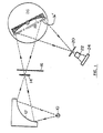
- a light source comprising a light generating device 10 and an elliptically curved concave mirror 12.
- the light generating device 10 provides polychromatic light in the ultraviolet, visual or infra-red region as required.
- a visual range or ultra-violet range light source is selected.
- ultra-violet/visual range light sources UV/VIS
- Such a light source provides a complete spectrum over the UV/VIS range most commonly used.
- the light reflected from the concave or elliptical mirror 12 is directed through a slit 14 and an optional filter wheel 16 to impinge upon a rotating optical grating 18.
- the optical grating 18 rotates about its optical axis with a preselected angular velocity.
- the light reflected from the optical grating 18 is then directed to and through a second slit 20 and through a sample chamber 22 to finally impinge upon a detector 24.
- the rotating optical grating 18 is mounted on a relatively heavy turntable 26.
- the filter wheel 16 is located just beyond the entrance slit 14. However, the filter wheel may be positioned ahead of the entrance slit 14 or on either side of the exit slit 20.
- the purpose of the filter wheel is to delete certain wave lengths from the spectrum sample and is a well known option in the spectroscopy field.
- the light generating means 10 is either a bulb providing the visual spectrum or a bulb providing the ultra-violet spectrum.
- a new bulb now being introduced by Hamamatsu Instruments of Japan provides the full range of ultraviolet and visual wavelengths from a single point source.
- the supporting wheel or turntable 26 for the optical grating 18 is preferably relatively heavy so as to act as a flywheel.
- the optical grating 18 itself may be suitably heavy because the increased inertia in the rotating assembly is advantageous in this spectrophotometer. Increased mass helps to retain a relatively constant angular velocity.
- the optical grating 18 and flywheel 26 are mounted on a vertical shaft 28 in turn mounted in bearings 30 and 32.
- the bearings as shown schematically at 30 and 32 are in turn mounted in a rigid supporting structure 34 and 36.
- the bearings 30 and 32 are selected for rotational accuracy to eliminate any possibility of translational vibration being transmitted to the optical grating 18.
- a drive motor 38 Illustrated next to the flywheel 26 and optical grating 18 is a drive motor 38 which is connected 40 to the flywheel 26.
- a suitable drive system may be a floppy disk drive motor or tape drive motor, selected from the many available for computers. Such a drive in combination with a relatively heavy fly wheel 26 will assure a sufficiently constant rotational velocity for the optical grating 18.
- an optical incremental shaft encoder 42,44 such as the HEDS 5000 by Hewlett Packard, which provides 500 pulses per revolution and an index pulse.
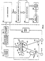
- Fig. 3 To the left side of Fig. 3 is a brief schematic of the spectrophotometer apparatus shown in Fig. 1.
- the light source to the lower left is the combination of the light generating means 10 and elliptical focusing mirror 12.
- the position of the index on the shaft encoder 42,44 is shown as a dark spot 46 that is about to enter the optical head 44 of the encoder.
- This logic circuit 50 comprises: timing circuitry adapted to measure the time intervals between successive pulses delivered by the optical head 44 of the encoder; memory for storing such successive time intervals (a number [n] of such time intervals being measured); computing means for extrapolating from the above data the expected time interval [n+l] for the angular distance between the two following markings and circuitry interpolating pulses corresponding to the angular positions representing the selected wavelengths.
- the wavelengths interpolated in time interval [n+l] are preferably equally spaced. This is based on the assumption that the angular velocity of the grating in the time interval corresponding to a few shaft encoder markings is sufficiently constant to justify such extrapolation and interpolation.
- the naturally occurring phenomena of the zero order spectrum directly depends on the position of the grating.
- the grating acts as a simple mirror reflecting polychromatic light onto the detector.
- This signal together with the index pulse initiated by dark spot 46 of the shaft encoder, which occurs once per revolution, is used by the calibration algorithm, to verify the angular position of the grating.
- the zero order is a strong signal easily distinguished from the subsequent spectral data.
- the index pulse is also fed to the filter wheel drive 54.
- This filter depends on the location thereof, either to eliminate undesired wavelengths from the incident light (when located between the entrance slit 14 and the grating 18) or to prevent higher order spectra from reaching the detector (when located between the grating 18 and exit slit 22).
- the filter wheel control 54 causes the filter wheel motor 37 to rotate the filter wheel 16 in synchronization with turntable 26.
- the location of the first wavelength of interest may be easily calculated from the position of the zero order signal and the index pulse. It is important that the utilization of the zero order signal, which is independent of the shaft encoder and dependent only on the actual angular position of the grating for continuous calibration, eliminates possible errors stemming from changes in the relative position of the grating and the shaft encoder. In effect, the grating angular position is recalibrated with each revolution.
- the electric signal from detector 24 (an analog value) is fed to the pre-amplifier 56.
- the A/D circuit 52 samples this electrical signal for every pulse received and digitizes the sample values, if desired.
- the result of this intermediate information processing stage is the desired spectra in the form of light intensity values as a function of wavelength.
- This intermediate result may be utilized directly in conventional ways, as above said, but the preferred embodiment of the invention is to transfer the output of the A/D circuit 52 in digital form to a scratch-pad memory 58 in real time for temporary storage.
- a computer and a program may be provided for transferring the data through the data bus of the computer to a fixed memory location, at a rate adequate for transfereing the data representing a single scan, thus preparing the scratch-pad memory for receiving a fresh burst of data representing the following revolution and scan.
- the unit for receiving the data and transferring the data for processing or to more permanent memory locations, possibly after appropriate selection and/or calculation is herein termed a data acquisition unit 60.
- the data acquisition unit 60 is followed by data processing unit 62 and data storage unit 64, two units which are interconnected and may be programmed in a variety of ways.
- Another unique feature of the monochromator of the present invention is the dark current measurement and compensation.
- a well known problem with detectors such as those of the silicon diode type used herein is that due to thermal effects, an output signal arises despite the lack of incident light. This, termed the dark current, must be compensated. Heretofore a most common way to accomplish such compensation is to activate a shutter to block the light and then measure the dark current.
- an almost continuous correction may be applied by measuring the detector output during the time for each revolution at which the back surface of the grating faces the detector.
- This back surface may be made non-reflecting by anodizing and coating with a non-reflecting material.
- the dark current output of the detector may be utilized at any suitable stage of the data acquisition process to correct the measured detector output.
- the most suitable point may be the data acquisition unit 60 where this dark current value can be temporarily stored in an appropriate memory location since this value is not concurrent with the spectral measurement data.
- this dark current value can be temporarily stored in an appropriate memory location since this value is not concurrent with the spectral measurement data.
- the time interval between measuring the spectrum and the dark current in the same revolution is very short, there is a distinct advantage. The possible error due to a drift in the dark current value is minimized, thereby decreasing thermal instability effects and reducing long term noise.
- the applications of applicant's new spectrophotometer are manifold.
- the rapid scan of the instrument permits each spectral element to be represented as a value and corresponding statistical uncertainty.
- the new spectrophotometer is capable of acquiring at least ten complete spectra per second (200 nm to 800 nm) with one nm resolution.
- the new instrument can be used for spectroelectrochemistry, stop flow kinetics and as a detector for liquid chromatography (HPLC) or gas chromatography.
- a second grating 18 ⁇ mounted back to back with the first grating and a second triggering means 46 ⁇ on the rotating flywheel or shaft permit a double sampling rate at the same angular velocity.
- filters 16 ⁇ can be mounted on the rotating turntable or flywheel 26 in front of the optical grating 18 to remove second order and other harmonic wavelengths without any weight penalty.
Landscapes
- Physics & Mathematics (AREA)
- Spectroscopy & Molecular Physics (AREA)
- General Physics & Mathematics (AREA)
- Spectrometry And Color Measurement (AREA)
- Investigating Or Analysing Materials By Optical Means (AREA)
Applications Claiming Priority (2)
| Application Number | Priority Date | Filing Date | Title |
|---|---|---|---|
| US8544 | 1987-01-29 | ||
| US07/008,544 US4804266A (en) | 1985-07-26 | 1987-01-29 | Continuously rotating grating rapid-scan spectrophotometer |
Publications (2)
| Publication Number | Publication Date |
|---|---|
| EP0277720A2 true EP0277720A2 (de) | 1988-08-10 |
| EP0277720A3 EP0277720A3 (de) | 1989-05-10 |
Family
ID=21732200
Family Applications (1)
| Application Number | Title | Priority Date | Filing Date |
|---|---|---|---|
| EP88300390A Withdrawn EP0277720A3 (de) | 1987-01-29 | 1988-01-19 | Schnellabtastspektralphotometer mit ununterbrochen drehendem Gitter |
Country Status (4)
| Country | Link |
|---|---|
| US (1) | US4804266A (de) |
| EP (1) | EP0277720A3 (de) |
| JP (1) | JPS63295934A (de) |
| IL (1) | IL85148A0 (de) |
Cited By (9)
| Publication number | Priority date | Publication date | Assignee | Title |
|---|---|---|---|---|
| EP0381053A1 (de) * | 1989-01-28 | 1990-08-08 | Shimadzu Corporation | Verfahren zum Betrieb eines Spektrophotometers |
| EP0420135A1 (de) * | 1989-09-27 | 1991-04-03 | Nirsystems Incorporated | Spektrophotometer mit Fehlerkorrektur durch schnelle Abtastung |
| EP0506063A2 (de) * | 1991-03-29 | 1992-09-30 | Shimadzu Corporation | Spektrophotometer |
| GB2293650A (en) * | 1994-09-30 | 1996-04-03 | Ando Electric | Optical spectrum measuring apparatus |
| EP0733197A1 (de) * | 1993-12-06 | 1996-09-25 | Analogic Corporation | Vorrichtung und verfahren zur messung von geometrischen, positionellen und kinematischen parametern einer rotierenden anordnung |
| EP0982581A1 (de) * | 1998-08-28 | 2000-03-01 | Perkin-Elmer Limited | Datenerfassung für die Spektroskopie |
| CN103033340A (zh) * | 2011-09-28 | 2013-04-10 | 中国科学院西安光学精密机械研究所 | 大口径取样光栅取样率的测试装置及测试方法 |
| CN103323123A (zh) * | 2013-06-25 | 2013-09-25 | 长沙理工大学 | 一种全自动的光波波长的测量方法及装置 |
| EP3299780A1 (de) * | 2016-09-26 | 2018-03-28 | Berthold Technologies GmbH & Co. KG | Verfahren und system zum spektroskopischen messen optischer eigenschaften von proben |
Families Citing this family (24)
| Publication number | Priority date | Publication date | Assignee | Title |
|---|---|---|---|---|
| US4988196A (en) * | 1989-04-17 | 1991-01-29 | Sperry Marine Inc. | Time domain Fraunhofer line discriminator |
| US5407638A (en) * | 1993-04-28 | 1995-04-18 | Shell Oil Company | Detector-cell adapted for continuous-flow absorption detection |
| US5408326A (en) * | 1993-04-28 | 1995-04-18 | Shell Oil Company | Dual-wavelength absorption detector adapted for continuous-flow detection |
| US5349183A (en) * | 1993-07-12 | 1994-09-20 | Rockwell International Corporation | Diffraction grating rotary speed sensor having a circumferentially variable pitch diffraction grating |
| US6204919B1 (en) | 1993-07-22 | 2001-03-20 | Novachem Bv | Double beam spectrometer |
| US5488240A (en) * | 1993-12-27 | 1996-01-30 | Hlousek; Louis | Apparatus and method for rotating an optical element using a moving coil in a constant magnetic field |
| DE69530766T2 (de) * | 1995-02-24 | 2004-05-19 | Anritsu Corp. | Einrichtung zum detektieren des rotationswinkels eines beugungsgitters |
| US6587199B1 (en) * | 2000-02-25 | 2003-07-01 | Sensys Medical, Inc. | Embedded data acquisition and control system for non-invasive glucose prediction instrument |
| US7216045B2 (en) * | 2002-06-03 | 2007-05-08 | Timbre Technologies, Inc. | Selection of wavelengths for integrated circuit optical metrology |
| JP2004077212A (ja) * | 2002-08-13 | 2004-03-11 | Agilent Technol Inc | 光信号の波長と波形を測定する装置 |
| US7099003B2 (en) * | 2003-05-09 | 2006-08-29 | Delta Search Labs, Inc. | Spectroscopic systems and methods |
| JP4416522B2 (ja) * | 2004-01-26 | 2010-02-17 | キヤノン株式会社 | 分光器 |
| US7483134B2 (en) * | 2005-02-10 | 2009-01-27 | Unity Scientific, Llc | Scanning monochromator with direct drive grating |
| US8903577B2 (en) * | 2009-10-30 | 2014-12-02 | Lsi Industries, Inc. | Traction system for electrically powered vehicles |
| US7598683B1 (en) * | 2007-07-31 | 2009-10-06 | Lsi Industries, Inc. | Control of light intensity using pulses of a fixed duration and frequency |
| US8604709B2 (en) | 2007-07-31 | 2013-12-10 | Lsi Industries, Inc. | Methods and systems for controlling electrical power to DC loads |
| CN101726359B (zh) * | 2008-10-30 | 2011-09-28 | 北京信息科技大学 | 多光栅单色仪及其定标方法 |
| JP5206322B2 (ja) * | 2008-10-31 | 2013-06-12 | 株式会社島津製作所 | 分光光度計 |
| US9404799B2 (en) * | 2013-03-15 | 2016-08-02 | Westco Scientific Instruments, Inc. | Tandem dispersive range monochromator |
| US9395245B2 (en) * | 2013-03-15 | 2016-07-19 | Westco Scientific Instruments, Inc. | Data knitting tandem dispersive range monochromator |
| CH709896A2 (de) * | 2014-07-18 | 2016-01-29 | Tecan Trading Ag | Monochromator mit schwingungsarm bewegbaren optischen Elementen. |
| US10215635B2 (en) * | 2017-01-26 | 2019-02-26 | Westco Scientific Instruments, Inc | Data blending multiple dispersive range monochromator |
| WO2021215034A1 (ja) * | 2020-04-23 | 2021-10-28 | 株式会社島津製作所 | 分光測定装置 |
| CN113280917B (zh) * | 2021-05-19 | 2023-05-02 | 苏州灵析精密仪器有限公司 | 高分辨率宽光谱校准光源 |
Citations (3)
| Publication number | Priority date | Publication date | Assignee | Title |
|---|---|---|---|---|
| US3637310A (en) * | 1969-04-01 | 1972-01-25 | Jeol Ltd | Liquid chromatograph for identifying chemical components by means of spectrometer |
| US4285596A (en) * | 1977-08-16 | 1981-08-25 | Neotec Corporation | Holographic diffraction grating system for rapid scan spectral analysis |
| US4540282A (en) * | 1983-03-21 | 1985-09-10 | Isaac Landa | Apparatus for optically analyzing a sample |
Family Cites Families (3)
| Publication number | Priority date | Publication date | Assignee | Title |
|---|---|---|---|---|
| US3447873A (en) * | 1966-03-10 | 1969-06-03 | Beckman Instruments Inc | Filter grating monochromator |
| US4293222A (en) * | 1978-02-27 | 1981-10-06 | Baxter Travenol Laboratories, Inc. | Control apparatus for spectrophotometer |
| GB2113830B (en) * | 1982-01-19 | 1985-05-01 | Philips Electronic Associated | Optimising operation of atomic spectrophotometers |
-
1987
- 1987-01-29 US US07/008,544 patent/US4804266A/en not_active Expired - Fee Related
-
1988
- 1988-01-19 EP EP88300390A patent/EP0277720A3/de not_active Withdrawn
- 1988-01-20 IL IL85148A patent/IL85148A0/xx unknown
- 1988-01-29 JP JP63019443A patent/JPS63295934A/ja active Pending
Patent Citations (3)
| Publication number | Priority date | Publication date | Assignee | Title |
|---|---|---|---|---|
| US3637310A (en) * | 1969-04-01 | 1972-01-25 | Jeol Ltd | Liquid chromatograph for identifying chemical components by means of spectrometer |
| US4285596A (en) * | 1977-08-16 | 1981-08-25 | Neotec Corporation | Holographic diffraction grating system for rapid scan spectral analysis |
| US4540282A (en) * | 1983-03-21 | 1985-09-10 | Isaac Landa | Apparatus for optically analyzing a sample |
Non-Patent Citations (2)
| Title |
|---|
| JOURNAL OF PHYSICS E. SCIENT. INSTRUMENTS, vol. 17, no. 6, June 1984, pages 517-520, Institute of Physics, Dorking, GB; M. BARCELLONA et al.: "A real-time-resolved scanning spectrophotometer with spectrum averaging capabilities" * |
| L'ONDE ELECTRIQUE, vol. 50, no. 2, February 1970, pages 136-140; A. DUCROS et al.: "Spectromètre ultra-rapide" * |
Cited By (17)
| Publication number | Priority date | Publication date | Assignee | Title |
|---|---|---|---|---|
| EP0381053A1 (de) * | 1989-01-28 | 1990-08-08 | Shimadzu Corporation | Verfahren zum Betrieb eines Spektrophotometers |
| US5268737A (en) * | 1989-01-28 | 1993-12-07 | Shimidzu Corporation Of 1 | Method and apparatus for calibrating a spectrophotometer |
| EP0420135A1 (de) * | 1989-09-27 | 1991-04-03 | Nirsystems Incorporated | Spektrophotometer mit Fehlerkorrektur durch schnelle Abtastung |
| EP0506063A2 (de) * | 1991-03-29 | 1992-09-30 | Shimadzu Corporation | Spektrophotometer |
| EP0506063A3 (en) * | 1991-03-29 | 1993-03-31 | Shimadzu Corporation | Spectrophotometer |
| US5223913A (en) * | 1991-03-29 | 1993-06-29 | Shimadzu Corporation | Spectrophotometer |
| EP0733197A1 (de) * | 1993-12-06 | 1996-09-25 | Analogic Corporation | Vorrichtung und verfahren zur messung von geometrischen, positionellen und kinematischen parametern einer rotierenden anordnung |
| EP0733197A4 (de) * | 1993-12-06 | 1997-02-12 | Analogic Corp | Vorrichtung und verfahren zur messung von geometrischen, positionellen und kinematischen parametern einer rotierenden anordnung |
| FR2725273A1 (fr) * | 1994-09-30 | 1996-04-05 | Ando Electric | Appareil de mesure de spectres optiques |
| GB2293650A (en) * | 1994-09-30 | 1996-04-03 | Ando Electric | Optical spectrum measuring apparatus |
| GB2293650B (en) * | 1994-09-30 | 1996-12-11 | Ando Electric | Optical spectrum measuring apparatus |
| US5784159A (en) * | 1994-09-30 | 1998-07-21 | Ando Electric Co., Ltd. | Optical spectrum measuring apparatus |
| EP0982581A1 (de) * | 1998-08-28 | 2000-03-01 | Perkin-Elmer Limited | Datenerfassung für die Spektroskopie |
| US6483113B1 (en) | 1998-08-28 | 2002-11-19 | Wellesley Inernational C.V. | Data collection in spectroscopy |
| CN103033340A (zh) * | 2011-09-28 | 2013-04-10 | 中国科学院西安光学精密机械研究所 | 大口径取样光栅取样率的测试装置及测试方法 |
| CN103323123A (zh) * | 2013-06-25 | 2013-09-25 | 长沙理工大学 | 一种全自动的光波波长的测量方法及装置 |
| EP3299780A1 (de) * | 2016-09-26 | 2018-03-28 | Berthold Technologies GmbH & Co. KG | Verfahren und system zum spektroskopischen messen optischer eigenschaften von proben |
Also Published As
| Publication number | Publication date |
|---|---|
| EP0277720A3 (de) | 1989-05-10 |
| IL85148A0 (en) | 1988-06-30 |
| US4804266A (en) | 1989-02-14 |
| JPS63295934A (ja) | 1988-12-02 |
Similar Documents
| Publication | Publication Date | Title |
|---|---|---|
| US4804266A (en) | Continuously rotating grating rapid-scan spectrophotometer | |
| US5489980A (en) | Apparatus for rapid and accurate analysis of the composition of samples | |
| US4540282A (en) | Apparatus for optically analyzing a sample | |
| US7796252B2 (en) | Scanning monochromator with direct drive grating | |
| US4264205A (en) | Rapid scan spectral analysis system utilizing higher order spectral reflections of holographic diffraction gratings | |
| US4732476A (en) | Continuously rotating grating rapid-scan spectrophotometer | |
| US4776695A (en) | High accuracy film thickness measurement system | |
| CN106404713A (zh) | 一种全谱段800nm‑2500nm的双探测器微型近红外光谱仪 | |
| JPH01197617A (ja) | 分光器 | |
| US6683686B2 (en) | Temporally resolved wavelength measurement method and apparatus | |
| US3879988A (en) | Optical comparator for measuring vibration on a rotating object | |
| US4762412A (en) | Optical scanning device | |
| US3637310A (en) | Liquid chromatograph for identifying chemical components by means of spectrometer | |
| US4227079A (en) | Multipath fine positioning beam director | |
| US3460892A (en) | Rapid scan spectrometer that sweeps corner mirrors through the spectrum | |
| JP3425448B2 (ja) | 光検出器の直線性決定方法および精密測光機器 | |
| US4971439A (en) | Wavelength calibration method and apparatus | |
| US6825922B2 (en) | Determination of the angular position of a laser beam | |
| GB2071311A (en) | Minimizing adverse phase change effects | |
| US3843259A (en) | Differential spectrophotometer | |
| CN210166031U (zh) | 基于扫描振镜的高速成像光谱仪 | |
| JP2865337B2 (ja) | 光学測定装置 | |
| US4577966A (en) | Spectrophotometer | |
| CA1310508C (en) | Opto-electronic method for spectral analysis | |
| SU609079A1 (ru) | Способ контрол плотности поверхностного сло твердых тел |
Legal Events
| Date | Code | Title | Description |
|---|---|---|---|
| PUAI | Public reference made under article 153(3) epc to a published international application that has entered the european phase |
Free format text: ORIGINAL CODE: 0009012 |
|
| AK | Designated contracting states |
Kind code of ref document: A2 Designated state(s): DE FR GB |
|
| RAP3 | Party data changed (applicant data changed or rights of an application transferred) |
Owner name: BARSPEC LIMITED |
|
| RIN1 | Information on inventor provided before grant (corrected) |
Inventor name: BARSHAD,YOAV |
|
| PUAL | Search report despatched |
Free format text: ORIGINAL CODE: 0009013 |
|
| AK | Designated contracting states |
Kind code of ref document: A3 Designated state(s): DE FR GB |
|
| 17P | Request for examination filed |
Effective date: 19890425 |
|
| 17Q | First examination report despatched |
Effective date: 19910411 |
|
| STAA | Information on the status of an ep patent application or granted ep patent |
Free format text: STATUS: THE APPLICATION IS DEEMED TO BE WITHDRAWN |
|
| 18D | Application deemed to be withdrawn |
Effective date: 19910822 |