EP0277370A2 - Dilatationskatheter mit Tandemballon - Google Patents
Dilatationskatheter mit Tandemballon Download PDFInfo
- Publication number
- EP0277370A2 EP0277370A2 EP87119371A EP87119371A EP0277370A2 EP 0277370 A2 EP0277370 A2 EP 0277370A2 EP 87119371 A EP87119371 A EP 87119371A EP 87119371 A EP87119371 A EP 87119371A EP 0277370 A2 EP0277370 A2 EP 0277370A2
- Authority
- EP
- European Patent Office
- Prior art keywords
- balloon
- balloons
- lumen
- elongate member
- flexible elongate
- Prior art date
- Legal status (The legal status is an assumption and is not a legal conclusion. Google has not performed a legal analysis and makes no representation as to the accuracy of the status listed.)
- Granted
Links
Images

Classifications
-
- A—HUMAN NECESSITIES
- A61—MEDICAL OR VETERINARY SCIENCE; HYGIENE
- A61M—DEVICES FOR INTRODUCING MEDIA INTO, OR ONTO, THE BODY; DEVICES FOR TRANSDUCING BODY MEDIA OR FOR TAKING MEDIA FROM THE BODY; DEVICES FOR PRODUCING OR ENDING SLEEP OR STUPOR
- A61M25/00—Catheters; Hollow probes
- A61M25/10—Balloon catheters
- A61M25/104—Balloon catheters used for angioplasty
-
- A—HUMAN NECESSITIES
- A61—MEDICAL OR VETERINARY SCIENCE; HYGIENE
- A61M—DEVICES FOR INTRODUCING MEDIA INTO, OR ONTO, THE BODY; DEVICES FOR TRANSDUCING BODY MEDIA OR FOR TAKING MEDIA FROM THE BODY; DEVICES FOR PRODUCING OR ENDING SLEEP OR STUPOR
- A61M25/00—Catheters; Hollow probes
- A61M25/10—Balloon catheters
- A61M25/1011—Multiple balloon catheters
-
- A—HUMAN NECESSITIES
- A61—MEDICAL OR VETERINARY SCIENCE; HYGIENE
- A61M—DEVICES FOR INTRODUCING MEDIA INTO, OR ONTO, THE BODY; DEVICES FOR TRANSDUCING BODY MEDIA OR FOR TAKING MEDIA FROM THE BODY; DEVICES FOR PRODUCING OR ENDING SLEEP OR STUPOR
- A61M25/00—Catheters; Hollow probes
- A61M2025/0004—Catheters; Hollow probes having two or more concentrically arranged tubes for forming a concentric catheter system
-
- A—HUMAN NECESSITIES
- A61—MEDICAL OR VETERINARY SCIENCE; HYGIENE
- A61M—DEVICES FOR INTRODUCING MEDIA INTO, OR ONTO, THE BODY; DEVICES FOR TRANSDUCING BODY MEDIA OR FOR TAKING MEDIA FROM THE BODY; DEVICES FOR PRODUCING OR ENDING SLEEP OR STUPOR
- A61M25/00—Catheters; Hollow probes
- A61M25/10—Balloon catheters
- A61M2025/1043—Balloon catheters with special features or adapted for special applications
- A61M2025/1079—Balloon catheters with special features or adapted for special applications having radio-opaque markers in the region of the balloon
-
- A—HUMAN NECESSITIES
- A61—MEDICAL OR VETERINARY SCIENCE; HYGIENE
- A61M—DEVICES FOR INTRODUCING MEDIA INTO, OR ONTO, THE BODY; DEVICES FOR TRANSDUCING BODY MEDIA OR FOR TAKING MEDIA FROM THE BODY; DEVICES FOR PRODUCING OR ENDING SLEEP OR STUPOR
- A61M25/00—Catheters; Hollow probes
- A61M25/01—Introducing, guiding, advancing, emplacing or holding catheters
- A61M25/0105—Steering means as part of the catheter or advancing means; Markers for positioning
- A61M25/0108—Steering means as part of the catheter or advancing means; Markers for positioning using radio-opaque or ultrasound markers
Definitions
- This invention relates to balloon dilatation catheters and more particularly to tandem balloon dilatation catheters.
- Balloon dilatation catheters have heretofore been provided.
- Such a procedure in the past has been time consuming. There is therefore a need for a new and improved balloon dilatation catheter.
- Another object of the invention is to provide a catheter and method of the above character in which the tandem balloons are of different sizes.
- Another object of the invention is to provide a catheter and method of the above character which utilizes a multi-port adapter to permit independent rapid inflation and deflation of the tandem balloons.
- Another object of the invention is to provide a dilatation catheter and method of the above character which is adapted to be used with movable and stationary guidewires.
- Another object of the invention is to provide a dilatation catheter and method of the above character in which the balloons can be readily vented.
- the tandem balloon dilatation catheter assembly of the present invention is comprised of an elongate member having first and second flow passages therein and having proximal and distal ends.
- First and second ballons are carried by the distall extremity of the flexible elongate member.
- the first balloon has a diameter substantially less than the diameter of the second balloon.
- a first balloon is disposed distally of the second balloon.
- Means is provided for establishing communication between the first of the flow passages and the interior of the first balloon as well as for establishing communication between the second lumen and the interior of the second balloon.
- Means is secured to the proximal extremity of the flexible elongate member permitting independent inflation and deflation of the first and second balloons through the first and second passages.
- Means is provided for venting at least one of the balloons.
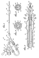
- the tandem balloon dilatation catheter assembly 11 consists of a flexible elongate tubular member 12 formed of a suitable flexible material such as plastic. Suitable materials are disclosed in U.S. Letters Patent 4,323,071.
- the flexible elongate member 12 is formed so that it provides at least first and second flow passages 13 and 14 extending longitudinally thereof (see Figure 2).
- the flexible elongate member 12 has proximal and distal extremities 16 and 17.
- the flow passage 13 and 14 can be formed in a suitable manner such as by providing a co-axial construction for the tubular member 12 such as shown in Figure 2 and as disclosed in U.S. Letters Patent No.
- First and second tandem balloons 21 and 22 are carried by the first distal extremity of the flexible elongate member 12.
- the first balloon 21 is distal of the second balloon 22 and preferably has the smaller size or smaller outside diameter than the diameter of the second balloon 22.
- the first balloon 21 can be referred to as a distal balloon with the second balloon 22 being referred to as the proximal balloon.
- means is provided for establishing communication between the first flow passage 13 and the interior of the balloon 21 by having the flow passage 13 open directly into the balloon 21.
- Means is also provided for establishing communication between the second flow passage 14 and the interior of the second balloon 22 by having the flow passage 14 open directly into the balloon 22.
- the inner tubular member 18 is provided with a continuous diameter extremity to near the distal extremity.
- the inner tubular member 18 is provided with necked-down portions 18b and 18c on its distal extremity of progressively smaller diameters. Portion 18b extends through the balloon 22 whereas portion 18c terminates at the junction of balloon 22 and the balloon 21.
- the first or distal balloon 21 can be formed of a separate tubular balloon member or it can be formed integral in the distal extremity of the inner tubular member 18. As shown in Figure 2 it is formed as a separate tubular member or component which has itts proximal necked-down extremity 23 secured to the portion 18c of the distal extremity of the inner tubular member 18 by suitable means such as by using heat shrinkable irradiated material for the balloon member or by utilizing an adhesive to form a fluid-tight seal.
- the necked-down distal extremity 24 of the balloon member 21 can be necked-down onto a spring tip 29 of a core wire 31 or by utilizing an adhesive to form suitable means such as a fluid-tight seal.
- the spring tip 29 can be formed in a manner described in U.S. Patent No. 4,538,622 and is formed of a suitable radiopaque material such as tungsten or platinum or a combination of the two.
- the spring tip 29 is secured to the distal extremity of the core wire 31 in a suitable manner such as by soldering and brazing.
- the core wire 31 can be formed of a suitable material such as stainless steel. Typically, it can be a diameter of 0.35 - 0.45 mm (.014 to .018 inch) with progressive tapers to smaller diameters along its distal extremity. As shown in Figure 2, the core wire 31 extends through the inner or first flow passage 13.
- the core wire 31 can have a portion 31a of a continuous diameter of 0.4 mm (.016 inch) from its proximal end for a distance of approximately 150 centimeters followed by a tapered portion 31b approximately 3 centimeters in length.
- the cylindrical portion 31c follows having a continuous diameter of .008 inch followed by a tapered portion 31d three centimeters in length which is followed by a flattened portion 31e having a thickness of 0.05 - 0.075 mm (.002 to .003 inch) and a length of .5 to 2 centimeters.
- the portion 31c extends through the balloons 21 and 22.
- the second or proximal balloon 22 can be formed integral with the outer tubular member 19 or if desired, it also can be formed as a separate tubular member and bonded thereto by suitable means such as an adhesive.
- the tubular member can be formed of a heat shrinkable irradiated material in which the distal necked-down extremity 36 can be secured to the proximal extremity of the first balloon 21 by suitable means such as by a shrink fit or by the use of an adhesive.
- An adapter assembly 41 is secured to the proximal extremity of the elongate member 12 and consists of a two-arm adapter 42 and a three-arm adapter 43.
- the two-arm adapter 42 consists of a central arm 44 and a side arm 46 and the three-arm adapter consists of a central arm 47 and side arms 48 and 49.
- the core wire or guide wire 31 extends through central arms 44 and 47 and is connected to a rotation limiting device 51.
- the arms 49 and 46 are in communication with the flow passages 13 and 14 respectively so that radiographic contrast liquid can be introduced into the passage for inflating and deflating the balloons 21 and 22. This can be accomplished by the use of an inflation/deflation device of the type disclosed by U.S. Patent No. 4,439,185 coupled to a valve fitting 52 connected to the arms 46 and 49.
- Suitable means is provided for venting air from the first and second balloons 21 and 22 as they are filled with the radiographic contrast liquid.
- a vent tube 56 of the type described in U.S. Letters Patent 4,323,071 can be utilized and introduced through the side arm 48 and into the first flow passage or lumen 13 until it extends near the distal extremity of the balloon 21.
- air in the balloon will be forced into the vent tube and vented to the atmosphere through its proximal extremity.
- vent tube (not shown) can be provided which is inserted into the second lumen or flow passage 14 and extended into the distal extremity of the balloon 22 so that any air collected in that balloon can also be vented to the atmosphere through the proximal extremity of the vent tube.
- alternative venting means can be utilized, such as a self-venting means in which a small passage 57 is provided (see Figures 3 and 4) for venting the proximal balloon 22 to the atmosphere.
- the above alternative vent design may also be used on the distal balloon 21, replacing the vent tube 56.
- markers which are substantially radiopaque can be provided in each of the balloons 21 and 22 so that the general location of the balloons 21 and 22 can be viewed under a fluoroscope. It should be appreciated that even though the markers 58 and 59 have been shown intermediate the ends of each of the balloons, that if desired two markers can be provided in each of the balloons with one near the distal extremity of the balloon and the other near the proximal extremity of the balloon so that the physician utilizing the catheter can readily ascertain the position of the balloons of the catheter with respect to a stenosis.
- a guiding catheter (not shown) is first inserted into the vessel by the use of a guide wire (not shown). The guide wire is then removed.
- the dilatation catheter assembly 11 prior to introduction of the guiding catheter has been prepared for insertion into the guiding catheter. This has been done by inflating the balloons 21 and 22 by inserting a suitable liquid such as a radiopaque contrast medium into the arms 46 and 49 to inflate the balloons 21 and 22 to ensure that all air is removed from the balloons.
- the balloons are then deflated by removing the radiopaque liquid.
- the tandem balloon dilatation catheter assembly is of a type shown in Figure 1 which uses a guidewire which is fixed at its distal extremity
- the dilatation catheter is inserted into the vessel by introducing the same into the guiding catheter and advancing the spring tip across the stenosis.
- the smaller or distal ballon 21 is advanced across the stenosis and inflated by introducing radiopaque contrast liquid into the balloon 21 through the arm 49.
- the second balloon 22 can then be advanced into the opening formed by the first balloon 21. It is then inflated by introducing radiopaque liquid through the arm 46. After this balloon 22 has been inflated, it is deflated and the catheter assembly can then be removed. Assuming that the angioplasty procedure has been successful, the guiding catheter can thereafter be removed.
- FIG. 5-8 Another embodiment of the invention is shown in Figures 5-8 in which a tandem balloon dilatation catheter assembly 61 is shown.
- the assembly 61 consists of an elongate flexible member 62 which is provided with proximal and distal ends. It also has at least first and second flow passages or lumens 63 and 64 which extend longitudinally of the elongate flexible member 62.
- an additional or third flow passage or lumen 66 is provided in the elongate flexible member 62.
- the flow passages or lumens 63, 64 and 66 can be provided in any suitable manner.
- a partial co-axial type construction can be utilized in which the elongate flexible member 62 is comprised of an inner tubular member 67 and an outer tubular member 68.
- the inner tubular member 67 has a flow passage or lumen 63 extending therethrough which serves as a balloon inflation lumen.
- the lumen 66 may also be utilized for distal radiopaque dye injection.
- the second flow passage or lumen 64 is formed by the annular space provided between the inner and outer tubular members 67 and 68.
- the third lumen 66 is provided within the inner tubular member 67 as shown particularly in Figure 6.
- the lumen 66 serves as the guide wire lumen and the lumen 63 serves as the inflation/deflation lumen.
- the inflation/deflation lumen 63 as shown can be substantially moon-shaped in cross section whereas the guide wire lumen 66 is generally circular in cross section. In this manner, it is possible to provide two lumens in the same inner tubular member without substantially increasing the overall cross-sectional diameter of the inner tubular member 67.
- all of the three flow passages or lumens 63, 64 and 66 can be formed in a single tubular member by providing two inflation lumens such as the inflation lumen 63 within the same tubular member and by providing a centrally disposed guide wire lumen 66 in the same tubular member. This can be readily accomplished by extruding such an elongate flexible member.
- the inner and outer tubular member 67 and 68 can be formed of a suitable material such as plastic, as hereinbefore described.
- First and second or distal and proximal dilatation balloons 71 and 72 are carried by the distal extremity of the elongate flexible member 62 and are arranged in tandem or in series as disclosed with respect to the first embodiment of the present invention.
- integral or separate balloons can be provided.
- a separate balloon 71 has been provided in which distal extremity of the ballon is necked down and sealed to the distal extremity of the inner tubular member 67 by suitable means such as an adhesive or a shrink fit.
- suitable means such as an adhesive or a shrink fit.
- the proximal extremity of the first balloon 71 is necked down and also fitted over the inner tubular member 67 and secured thereto by suitable means such as an adhesive provide a fluid-tight seal.
- Means is provided for establishing communication betwen the balloon inflation lumen 63 and the interior of the first balloon 71 and consists of a port 73 formed in the side wall forming the inner tubular member 67 adjacent the proximal extremity of the balloon 71 which opens into the balloon inflation lumen 63.
- Means is provided for venting the balloon 71 so that entrapped air therein can escape when the balloon is inflated and consists of the previously mentioned self-venting means.
- the self-vent is formed as a small bore or passage 74 in the distal extremity of the balloon 71.
- a vent tube or port leading into an inner lumen 66 can be used.
- the second balloon 72 as shown is formed integral with the outer tubular member 68 and has its distal extremity secured over the proximal extremity of the first balloon 71 and is secured thereto by suitable means such as an adhesive to also provide a fluid-tight seal. As shown, the interior of the second balloon 72 is in communication with the balloon inflation lumen 64. Means is also provided for venting the balloon 72. This also can be a self-vent provided by a small passage or bore 75 in the distal extremity of the balloon. Alternatively, a vent tube can be used.
- Radiopaque markers 76 and 77 of a suitable type, as for example, gold bands are mounted within the first and second balloons 71 and 72 so that the positioning of the balloons during an angioplasty procedure can be ascertained. As shown, a single marker 76 is provided between the distal and proximal extremities of the first balloon 71 and similarly, a single marker 77 has been provided between the proximal and distal extremities of the second balloon 72. It should be appreciated that if desired additional markers can be utilized in each of the balloons as, for example, placing a marker adjacent the distal and proximal extremities of the balloon rather than in the center of the balloon.
- a guide wire 81 of a conventional construction is provided for use with the catheter assembly 61. It is preferably of the torquable type and is provided with a spring tip 82 which is secured to a shaft 83.
- the portions of the inner and outer tubular members 67 and 68 near the distal extremities have been necked down to accommodate the balloons 71 and 72 and to make it possible to provide relatively low profiles for the balloons while still retaining good flow characteristics in the distal extremities of the inner and outer tubular members 67 and 68.
- a catheter assembly which still provides good flow characteristics with relatively thick walls being provided to provide added stiffness for the catheter assembly.
- the embodiment of the catheter assembly 61 can be provided with an adapter assembly of the type similar to the adapter assembly described in connection with the catheter assembly shown in Figure 1 which is provided with balloon inflation ports and a guide wire port.
- tandem balloon catheter assemblies have been provided in which the first balloon has diameters ranging from 1.5 and 2.5 millimeters and the second or larger balloon has diameters ranging from 2.5 to 4.0 millimeters.
- the procedure for use of the tandem balloon dilatation catheter assembly of the type shown in Figure 5 which utilizes a movable guide wire is very similar to that described in Figure 1 with the exception that the guide wire 81 is first introduced into the guiding catheter with the spring tip being advanced into the stenosis.
- the catheter assembly 61 is advanced over the guide wire.
- the balloons 71 and 72 are used in a similar two-step procedure to open the stenosis. After the two balloons have been inflated and deflated, the catheter assembly 61 with the guide wire 81 can be removed. Thereafter, the guiding catheter can be removed.
- the balloon dilatation catheter assembly of the present invention is particularly useful in opening very tight stenoses by utilizing a two-step procedure.
- the smaller distal balloon can be utilized to enter the tight stenosis because of its smaller profile.
- the higher profile proximal balloon can be advanced into the stenosis and inflated to complete the dilatation of the stenosis.
- tandem balloon dilatation catheter assemblies By utilizing such tandem balloon dilatation catheter assemblies, it is possible to eliminate the use of a plurality of balloon dilatation catheters of increasing size in an angioplasty procedure to achieve the desired opening of the stenosis. By eliminating the use of a plurality of catheters and by providing balloon dilatation catheter assemblies having tandem balloons, it is possible to reduce the amount of time and manipulations required in performing an angioplasty procedure.
- tandem balloon dilatation catheter assembly shown in Figure 1 only utilizes two balloons, it is poossible if desired to provide additional balloons in tandem having still larger diameters if this is found to be necessary.
Applications Claiming Priority (2)
| Application Number | Priority Date | Filing Date | Title |
|---|---|---|---|
| US69687A | 1987-01-06 | 1987-01-06 | |
| US696 | 1987-01-06 |
Publications (3)
| Publication Number | Publication Date |
|---|---|
| EP0277370A2 true EP0277370A2 (de) | 1988-08-10 |
| EP0277370A3 EP0277370A3 (en) | 1988-08-17 |
| EP0277370B1 EP0277370B1 (de) | 1992-06-03 |
Family
ID=21692647
Family Applications (1)
| Application Number | Title | Priority Date | Filing Date |
|---|---|---|---|
| EP19870119371 Expired EP0277370B1 (de) | 1987-01-06 | 1987-12-30 | Dilatationskatheter mit Tandemballon |
Country Status (4)
| Country | Link |
|---|---|
| EP (1) | EP0277370B1 (de) |
| JP (1) | JPS63240876A (de) |
| AU (1) | AU610548B2 (de) |
| DE (1) | DE3779613D1 (de) |
Cited By (11)
| Publication number | Priority date | Publication date | Assignee | Title |
|---|---|---|---|---|
| EP0358117A2 (de) * | 1988-09-06 | 1990-03-14 | Advanced Cardiovascular Systems, Inc. | Zusammengesetzter Gefässkatheter |
| EP0479557A1 (de) * | 1990-10-03 | 1992-04-08 | Hector D. Barone | Ballongerät zum Einpflanzen einer aortischen, intraluminalen Prothese |
| EP0479730A1 (de) * | 1990-10-04 | 1992-04-08 | Schneider (Europe) Ag | Ballondilationskatheter |
| FR2669826A1 (fr) * | 1990-11-30 | 1992-06-05 | Plowiecki Leopold | Catheter pour la dilatation des arteres. |
| GB2272159A (en) * | 1992-11-10 | 1994-05-11 | Andreas G Constantinides | Surgical/diagnostic aid |
| US5320604A (en) * | 1991-04-24 | 1994-06-14 | Baxter International Inc. | Low-profile single-lumen dual-balloon catheter with integrated guide wire for embolectomy dilatation/occlusion and delivery of treatment fluid |
| US5454788A (en) * | 1991-04-24 | 1995-10-03 | Baxter International Inc. | Exchangeable integrated-wire balloon catheter |
| US5613949A (en) * | 1994-04-01 | 1997-03-25 | Advanced Cardiovascular Systems, Inc. | Double balloon catheter assembly |
| US5632760A (en) * | 1994-10-20 | 1997-05-27 | Cordis Corporation | Balloon catheter for stent implantation |
| US5846246A (en) * | 1994-10-21 | 1998-12-08 | Cordis Corporation | Dual-balloon rapid-exchange stent delivery catheter with guidewire channel |
| CN113211760A (zh) * | 2013-08-28 | 2021-08-06 | 明讯科技有限公司 | 用于提供不透射线医用球囊的设备和方法 |
Citations (5)
| Publication number | Priority date | Publication date | Assignee | Title |
|---|---|---|---|---|
| CH616337A5 (de) * | 1977-10-21 | 1980-03-31 | Schneider Medintag Ag | |
| US4323071A (en) * | 1978-04-24 | 1982-04-06 | Advanced Catheter Systems, Inc. | Vascular guiding catheter assembly and vascular dilating catheter assembly and a combination thereof and methods of making the same |
| CH654214A5 (en) * | 1981-12-12 | 1986-02-14 | Schneider Medintag Ag | Dilating catheter arrangement |
| EP0213752A1 (de) * | 1985-07-30 | 1987-03-11 | Advanced Cardiovascular Systems, Inc. | Steuerbarer Ballondilatationskatheter mit Farbstoffinjektions- und Druckmessungsanordnungen |
| EP0241038A2 (de) * | 1986-04-09 | 1987-10-14 | TERUMO KABUSHIKI KAISHA trading as TERUMO CORPORATION | Katheter für die Wiederherstellung von Blutgefässen |
Family Cites Families (2)
| Publication number | Priority date | Publication date | Assignee | Title |
|---|---|---|---|---|
| US4148307A (en) * | 1975-12-26 | 1979-04-10 | Olympus Optical Company Limited | Tubular medical instrument having a flexible sheath driven by a plurality of cuffs |
| US4546759A (en) * | 1983-07-29 | 1985-10-15 | Mladen Solar | Method and apparatus for assisting human heart function |
-
1987
- 1987-12-30 DE DE8787119371T patent/DE3779613D1/de not_active Expired - Lifetime
- 1987-12-30 EP EP19870119371 patent/EP0277370B1/de not_active Expired
-
1988
- 1988-01-06 AU AU10076/88A patent/AU610548B2/en not_active Ceased
- 1988-01-06 JP JP63001130A patent/JPS63240876A/ja active Pending
Patent Citations (6)
| Publication number | Priority date | Publication date | Assignee | Title |
|---|---|---|---|---|
| CH616337A5 (de) * | 1977-10-21 | 1980-03-31 | Schneider Medintag Ag | |
| US4323071A (en) * | 1978-04-24 | 1982-04-06 | Advanced Catheter Systems, Inc. | Vascular guiding catheter assembly and vascular dilating catheter assembly and a combination thereof and methods of making the same |
| US4323071B1 (de) * | 1978-04-24 | 1990-05-29 | Advanced Cardiovascular System | |
| CH654214A5 (en) * | 1981-12-12 | 1986-02-14 | Schneider Medintag Ag | Dilating catheter arrangement |
| EP0213752A1 (de) * | 1985-07-30 | 1987-03-11 | Advanced Cardiovascular Systems, Inc. | Steuerbarer Ballondilatationskatheter mit Farbstoffinjektions- und Druckmessungsanordnungen |
| EP0241038A2 (de) * | 1986-04-09 | 1987-10-14 | TERUMO KABUSHIKI KAISHA trading as TERUMO CORPORATION | Katheter für die Wiederherstellung von Blutgefässen |
Cited By (15)
| Publication number | Priority date | Publication date | Assignee | Title |
|---|---|---|---|---|
| EP0358117A3 (en) * | 1988-09-06 | 1990-08-01 | Advanced Cardiovascular Systems, Inc. | Composite vascular catheter |
| EP0358117A2 (de) * | 1988-09-06 | 1990-03-14 | Advanced Cardiovascular Systems, Inc. | Zusammengesetzter Gefässkatheter |
| EP0479557A1 (de) * | 1990-10-03 | 1992-04-08 | Hector D. Barone | Ballongerät zum Einpflanzen einer aortischen, intraluminalen Prothese |
| US5413581A (en) * | 1990-10-04 | 1995-05-09 | Schneider (Europe) A.G. | Method of using a balloon dilatation catheter and a guidewire |
| EP0479730A1 (de) * | 1990-10-04 | 1992-04-08 | Schneider (Europe) Ag | Ballondilationskatheter |
| US5776101A (en) * | 1990-10-04 | 1998-07-07 | Schneider (Europe) A.G. | Balloon dilatation catheter |
| FR2669826A1 (fr) * | 1990-11-30 | 1992-06-05 | Plowiecki Leopold | Catheter pour la dilatation des arteres. |
| US5320604A (en) * | 1991-04-24 | 1994-06-14 | Baxter International Inc. | Low-profile single-lumen dual-balloon catheter with integrated guide wire for embolectomy dilatation/occlusion and delivery of treatment fluid |
| US5454788A (en) * | 1991-04-24 | 1995-10-03 | Baxter International Inc. | Exchangeable integrated-wire balloon catheter |
| GB2272159A (en) * | 1992-11-10 | 1994-05-11 | Andreas G Constantinides | Surgical/diagnostic aid |
| US5613949A (en) * | 1994-04-01 | 1997-03-25 | Advanced Cardiovascular Systems, Inc. | Double balloon catheter assembly |
| US5632760A (en) * | 1994-10-20 | 1997-05-27 | Cordis Corporation | Balloon catheter for stent implantation |
| US5733299A (en) * | 1994-10-20 | 1998-03-31 | Cordis Corporation | Two balloon catheter |
| US5846246A (en) * | 1994-10-21 | 1998-12-08 | Cordis Corporation | Dual-balloon rapid-exchange stent delivery catheter with guidewire channel |
| CN113211760A (zh) * | 2013-08-28 | 2021-08-06 | 明讯科技有限公司 | 用于提供不透射线医用球囊的设备和方法 |
Also Published As
| Publication number | Publication date |
|---|---|
| DE3779613D1 (de) | 1992-07-09 |
| EP0277370B1 (de) | 1992-06-03 |
| AU610548B2 (en) | 1991-05-23 |
| AU1007688A (en) | 1988-07-07 |
| JPS63240876A (ja) | 1988-10-06 |
| EP0277370A3 (en) | 1988-08-17 |
Similar Documents
| Publication | Publication Date | Title |
|---|---|---|
| US5002532A (en) | Tandem balloon dilatation catheter | |
| CA1287539C (en) | Dilatation catheter with angled balloon | |
| US4771778A (en) | Steerable low profile balloon dilatation catheter | |
| US5449343A (en) | Steerable dilatation catheter | |
| EP0213750B1 (de) | Selbstventilierender Ballondilatationskatheter | |
| US5387193A (en) | Balloon dilation catheter with hypotube | |
| AU610846B2 (en) | Liquid filled low profile dilatation catheter | |
| EP0274129B1 (de) | Verstärkter Ballon-Dilatationskatheter mit geschlitzter Austauschmanschette und Methode | |
| CA1320891C (en) | Steerable dilatation catheter | |
| CA1289838C (en) | Perfusion type balloon dilatation catheter and apparatus | |
| US4821722A (en) | Self-venting balloon dilatation catheter and method | |
| US5242394A (en) | Steerable dilatation catheter | |
| US5545138A (en) | Adjustable stiffness dilatation catheter | |
| USRE33166E (en) | Steerable dilatation catheter | |
| US4692200A (en) | Self-venting balloon dilatation catheter and method | |
| EP0492361A1 (de) | Festdraht Dilatationskatheter mit drehbare Ballonanordnung | |
| US20030040769A1 (en) | Single lumen rapid-exchange catheter | |
| WO1989004686A1 (en) | Angioplasty dilating guide wire | |
| US5256143A (en) | Self-venting balloon dilatation catheter | |
| EP0277370B1 (de) | Dilatationskatheter mit Tandemballon | |
| EP0442480A1 (de) | Ballonkatheter zur Ausdehnung der prostatischen Urethra | |
| USRE35176E (en) | Self-venting balloon dilatation catheter and method | |
| EP0288833A1 (de) | Ballondilatationskatheter, geeignet zum Laserschneiden |
Legal Events
| Date | Code | Title | Description |
|---|---|---|---|
| PUAI | Public reference made under article 153(3) epc to a published international application that has entered the european phase |
Free format text: ORIGINAL CODE: 0009012 |
|
| PUAL | Search report despatched |
Free format text: ORIGINAL CODE: 0009013 |
|
| AK | Designated contracting states |
Kind code of ref document: A2 Designated state(s): CH DE FR GB IT LI NL |
|
| AK | Designated contracting states |
Kind code of ref document: A3 Designated state(s): CH DE FR GB IT LI NL |
|
| 17P | Request for examination filed |
Effective date: 19890111 |
|
| 17Q | First examination report despatched |
Effective date: 19900903 |
|
| GRAA | (expected) grant |
Free format text: ORIGINAL CODE: 0009210 |
|
| AK | Designated contracting states |
Kind code of ref document: B1 Designated state(s): CH DE FR GB IT LI NL |
|
| PG25 | Lapsed in a contracting state [announced via postgrant information from national office to epo] |
Ref country code: IT Free format text: LAPSE BECAUSE OF FAILURE TO SUBMIT A TRANSLATION OF THE DESCRIPTION OR TO PAY THE FEE WITHIN THE PRE;WARNING: LAPSES OF ITALIAN PATENTS WITH EFFECTIVE DATE BEFORE 2007 MAY HAVE OCCURRED AT ANY TIME BEFORE 2007. THE CORRECT EFFECTIVE DATE MAY BE DIFFERENT FROM THE ONE RECORDED.SCRIBED TIME-LIMIT Effective date: 19920603 Ref country code: FR Effective date: 19920603 Ref country code: NL Effective date: 19920603 Ref country code: DE Effective date: 19920603 |
|
| REF | Corresponds to: |
Ref document number: 3779613 Country of ref document: DE Date of ref document: 19920709 |
|
| EN | Fr: translation not filed | ||
| NLV1 | Nl: lapsed or annulled due to failure to fulfill the requirements of art. 29p and 29m of the patents act | ||
| PG25 | Lapsed in a contracting state [announced via postgrant information from national office to epo] |
Ref country code: GB Effective date: 19921230 |
|
| PG25 | Lapsed in a contracting state [announced via postgrant information from national office to epo] |
Ref country code: LI Effective date: 19921231 Ref country code: CH Effective date: 19921231 |
|
| PLBE | No opposition filed within time limit |
Free format text: ORIGINAL CODE: 0009261 |
|
| STAA | Information on the status of an ep patent application or granted ep patent |
Free format text: STATUS: NO OPPOSITION FILED WITHIN TIME LIMIT |
|
| 26N | No opposition filed | ||
| GBPC | Gb: european patent ceased through non-payment of renewal fee |
Effective date: 19921230 |
|
| REG | Reference to a national code |
Ref country code: CH Ref legal event code: PL |