EP0277338B1 - Aerodynamische Fenstereinrichtung - Google Patents
Aerodynamische Fenstereinrichtung Download PDFInfo
- Publication number
- EP0277338B1 EP0277338B1 EP87118939A EP87118939A EP0277338B1 EP 0277338 B1 EP0277338 B1 EP 0277338B1 EP 87118939 A EP87118939 A EP 87118939A EP 87118939 A EP87118939 A EP 87118939A EP 0277338 B1 EP0277338 B1 EP 0277338B1
- Authority
- EP
- European Patent Office
- Prior art keywords
- side wall
- aerodynamic window
- diffuser
- laser cavity
- adjustable
- Prior art date
- Legal status (The legal status is an assumption and is not a legal conclusion. Google has not performed a legal analysis and makes no representation as to the accuracy of the status listed.)
- Expired - Lifetime
Links
Images


Classifications
-
- H—ELECTRICITY
- H01—ELECTRIC ELEMENTS
- H01S—DEVICES USING THE PROCESS OF LIGHT AMPLIFICATION BY STIMULATED EMISSION OF RADIATION [LASER] TO AMPLIFY OR GENERATE LIGHT; DEVICES USING STIMULATED EMISSION OF ELECTROMAGNETIC RADIATION IN WAVE RANGES OTHER THAN OPTICAL
- H01S3/00—Lasers, i.e. devices using stimulated emission of electromagnetic radiation in the infrared, visible or ultraviolet wave range
- H01S3/02—Constructional details
- H01S3/03—Constructional details of gas laser discharge tubes
- H01S3/036—Means for obtaining or maintaining the desired gas pressure within the tube, e.g. by gettering, replenishing; Means for circulating the gas, e.g. for equalising the pressure within the tube
-
- H—ELECTRICITY
- H01—ELECTRIC ELEMENTS
- H01S—DEVICES USING THE PROCESS OF LIGHT AMPLIFICATION BY STIMULATED EMISSION OF RADIATION [LASER] TO AMPLIFY OR GENERATE LIGHT; DEVICES USING STIMULATED EMISSION OF ELECTROMAGNETIC RADIATION IN WAVE RANGES OTHER THAN OPTICAL
- H01S3/00—Lasers, i.e. devices using stimulated emission of electromagnetic radiation in the infrared, visible or ultraviolet wave range
- H01S3/02—Constructional details
- H01S3/03—Constructional details of gas laser discharge tubes
- H01S3/034—Optical devices within, or forming part of, the tube, e.g. windows, mirrors
- H01S3/0343—Aerodynamic windows
Definitions
- the invention relates to an aerodynamic window device for a laser for the pressure shielding of the laser cavity and for coupling out the laser beam, comprising a jet nozzle, a diffuser lying opposite it, for generating a free jet extending from the jet nozzle to the diffuser and covering a coupling-out opening, a predetermined free jet being a pressure difference to be achieved is assigned, and a side wall of the diffuser facing away from the laser cavity, which can be adjusted relative to a free jet direction.
- the invention further relates to a method for pressure shielding a laser cavity by means of an aerodynamic window device for decoupling the laser beam, the aerodynamic window device comprising a jet nozzle, a diffuser opposite it for generating a free jet running from the jet nozzle to the diffuser and covering a decoupling opening, and an adjustable laser cavity Has side wall of the diffuser facing away, and wherein a free jet is given and this is assigned a pressure difference to be achieved by calculation.
- Aerodynamic window devices are known from the publication by RN Guile, AIAA Paper 75-122, 1975, "Investigation of a free-vortex aerodynamic window".
- this document discloses an aerodynamic window, in which the side wall of the diffuser facing away from the laser cavity is adjustable, the adjustability of the side wall only serves, according to the document, to create an adjustment possibility in order to match the Catch free air entrained air without affecting the function of the aerodynamic window.
- the object of the invention is to improve an aerodynamic window of the generic type in such a way that it allows the pressure level in the laser cavity to be set as simply as possible.
- adjusting members are provided for adjusting the side wall or its partial areas, in that the adjusting members are provided with actuating devices and in that a control is provided for the actuating devices, which is used for this purpose by the the pressure level in the laser cavity assigned to the predetermined free jet and the pressure difference to be achieved restores the pressure shielding of the laser cavity by adjusting at least partial areas of the side wall of the diffuser facing away from the laser cavity.
- This adjustability of the side wall of the diffuser allows the pressure level prevailing in the laser cavity to be varied, so that an undesired leakage current can be prevented by readjusting the side wall of the diffuser by means of the control when printing within a certain variation range.
- a simple embodiment of the aerodynamic window device provides that the entire side wall is adjustable as a whole.
- a diffuser lip of the side wall arranged on the inlet side can be adjusted, it also being within the scope of the invention if the diffuser lip can be adjusted alone or together with the entire side wall.
- an outlet-side part of the side wall is adjustable is with which a flow pattern in the diffuser itself can be influenced.
- this includes both a parallel displacement and a tilting of the side wall or its partial areas. Since a height of the diffuser, i.e. a distance of the movable side wall from the side facing the laser cavity can be determined quite well in advance and only contributes to a lesser extent to the adjustability of the pressure level in the laser cavity, is provided in an embodiment of the aerodynamic window device according to the invention which is as simple as possible and yet sufficiently adjustable that: the adjustable side wall or its partial areas can be tilted relative to the free jet direction.
- the adjustable side wall or its partial areas can be displaceable approximately parallel to the free jet direction. Since the free jet direction extends transversely to a longitudinal central axis of the coupling-out channel, the described displaceability of the side wall or its partial regions is consequently to be understood as a displaceability transverse to the longitudinal central axis of the coupling-out channel.
- adjustable side wall or its partial areas can be displaced approximately perpendicular to the longitudinal center axis of the coupling channel forming the coupling opening.
- the diffuser lip is adjustable.
- this requires a complex construction, so that the entire side wall should advantageously be adjustable when the diffuser lip is stationary.
- the diffuser lip of the adjustable side wall is bent in the direction of the side wall facing the laser cavity, since this allows a more favorable flow pattern in the diffuser and also improves the adjustment properties of such a diffuser.
- the adjusting elements can in principle be arranged in any direction to one another.
- An expedient embodiment provides that the setting elements are arranged parallel to one another.
- An even better adjustability of the side wall or its partial areas can, however, be achieved in that the adjusting members are arranged approximately at a right angle to one another.
- the side wall or its partial area is articulated on one of the adjusting members and articulated and displaceable on the other, so that the side wall can be tilted by adjusting one adjusting member and the inner wall linearly by adjusting the other adjusting member is movable.
- an embodiment has proven particularly useful in which a the first adjusting element is arranged approximately parallel to the longitudinal center line of the coupling-out channel and a second adjusting element is arranged transversely, in particular approximately at right angles thereto, and is articulated and transversely displaceable on the side wall or its partial areas on the first adjusting element and articulated on the second adjusting element.
- a particularly simple way of adjusting the side wall provides that the adjusting elements are adjusting screws or micrometer screws.
- the adjusting screws When using such adjusting screws, it is advantageous if the adjusting screws have spherical pressure pieces which engage in spherical recesses in the adjustable partial areas of the side wall, in order to be able to compensate in a simple manner for any tilting of the partial areas occurring during the adjustment relative to the pressure pieces of the adjusting screws.
- control system adjusts the side wall or its partial areas when an undesired leakage current occurs.
- a leakage current can be determined particularly easily for the control if the control is assigned a pressure sensor arranged on the cavity side near the decoupling opening and a pressure sensor located in the area of the laser cavity, which indicate a pressure difference in the event of a leakage current and thus make a leakage current recognizable for the control .
- An advantageous alternative to control by means of pressure sensors provides, in a further exemplary embodiment, that a gas flow sensor arranged on the cavity side near the outcoupling opening is provided for controlling the pressure level.
- This gas flow sensor is expediently a thermal anemometer.
- the above-mentioned object is further achieved according to the invention in a method of the type mentioned at the outset in that, in the case of a pressure level in the laser cavity deviating from the calculated pressure difference and with the predetermined free jet for setting the pressure shielding, the side wall of the diffuser facing away from the laser cavity, at least in some areas relative to that Free jet direction is adjusted.
- This method has the great advantage that it allows the aerodynamic window device to be easily adapted to different pressure levels in the laser cavity.
- This method can be carried out manually or automatically or at least remotely.
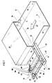
- a gas laser with a decoupling device according to the invention in FIG. 1 shows in detail a gas channel 12 which is formed from a base part 14, two side parts 16 and 18 and a cover 20. Excited laser gas flows through this gas channel 12 in the direction of arrow 22.
- a side channel 26 extends from an opening 24 in the side part 16 in a direction approximately perpendicular to the side part 16 and is closed at its end opposite the opening 24 by means of a rear wall 28.
- This side channel 26 is followed by an outcoupling channel 30 leading away from it at approximately a right angle and having a longitudinal central axis 31, which carries an aerodynamic window 32 at its end facing away from the side channel 26.
- a laser cavity 34 extends along a resonator axis 36, to which a first resonator mirror 38 is concentrically arranged on the side part 18 and a second resonator mirror 40 is adjustably arranged on the rear wall 28 of the side channel 26. Furthermore, the laser cavity 34 also comprises a coupling-out mirror 42 arranged in front of the second resonator mirror 40, which is also concentric to the resonator axis 36, but is inclined at 45 ° relative to the latter, so that it reflects approximately parallel rays into the coupling channel 30 to the resonator axis 36.
- the coupling-out mirror 42 has a central opening 44, which allows laser beams parallel to the resonator axis and extending to this to a certain minimum distance to pass through to the second resonator mirror 40.
- the resonator comprising the resonator mirrors 38 and 40, operates as an optically unstable resonator, that is to say the first resonator mirror 38 has a concave curvature, while the second resonator mirror 40 has a convex curvature, and both curvatures are matched to one another such that initially in the region of the Laser beams arising from the resonator axis are repeatedly reflected back and forth between the resonator mirrors 38 and 40 and thereby increasingly move away from the resonator axis 36 until they can no longer pass through the opening 44, but instead hit the coupling-out mirror 42, which enters the coupling-out channel 30 reflected from where they exit through the aerodynamic window 32.
- the aerodynamic window 32 shown enlarged in FIG. 2, comprises in particular an outlet opening 46 with a rectangular cross section, to the side edge 48 of which a jet nozzle 50 with its jet opening 52 is connected, the jet opening 52 extending over the entire width of the side edge 48 .
- the jet nozzle 50 comprises a gas supply channel 54, to which a Laval nozzle 56 connects, which carries a subsequent nozzle manifold 58 with a parallel supersonic flow.
- the nozzle manifold 58 ends with the jet opening 52 already described.
- Such a jet nozzle 50 imparts a velocity distribution of the free vortex to an open jet emerging from its jet opening 52, so that the free jet is curved in the direction of the outlet opening 46.
- this free jet is assigned a free jet direction 68, which is approximately perpendicular to the longitudinal center axis 31 of the coupling-out channel 30.
- Both the gas supply channel 54 and the Laval nozzle 56 and the nozzle manifold 58 are formed by two nozzle inserts 60 and 62, which lie between a base plate 64 and a cover plate 66, which in turn also limit the coupling-out channel 30 in the areas running perpendicular to the side edge 48 and therefore have a distance from one another which corresponds exactly to the length of the side edge 48.
- the base plate 64 and the cover plate 66 thus also form the free jet parallel to the side walls delimiting the free jet direction indicated by arrow 68.
- a diffuser Connected to a side edge 70 of the outlet opening 46 opposite the side edge 48 is a diffuser, designated as a whole by 72, into which the free jet spanning the outlet opening 46 flows through an inlet opening 74 facing the jet opening 52.
- the diffuser 72 is aligned with its longitudinal axis 73 at an acute angle of ⁇ 90 ° to the longitudinal central axis 31 of the decoupling channel 30.
- a diffuser channel 76 which is likewise delimited by the base plate 64 and the cover plate 66, is delimited on its side facing the laser cavity 34 by a stationary side wall 78 which is held on the base plate 64 and the cover plate 66 and which is flush with the side edge 70 of the outlet opening 46.
- a movable side wall 80 is provided which, although sealingly with the base plate 64 and the cover plate 66, is movably mounted between these and relative to the stationary side wall 78.
- This movable mounting of the side wall 80 takes place via two micrometer screws 86, which are arranged at a distance from one another, as seen in the flow direction 84 of the diffuser channel 76 and 88, which in turn are mounted on a support plate 82 which extends between the base plate 64 and the cover plate 66 and is held thereon.
- micrometer screws 86 and 88 have adjustable pressure pieces 90 and 92, the ends of which are provided with ball heads 94 and 96. These spherical heads engage in the spherical recesses 98 and 100 incorporated in the movable side wall 80 and together with them form an articulated and adjustable bearing for the movable side wall 80 by means of the micrometer screws 86 and 88.
- the movable side wall 80 forms with its in the region of the inlet opening 74 Diffuser channel 76 delimiting wall area a diffuser lip 102 which, with an inner surface 104 delimiting the diffuser channel 76, forms an angle with respect to an inner surface 106 of edge regions lying downstream in the longitudinal direction 84 of the diffuser channel 76, which is approximately 10 °. In other exemplary embodiments, however, this angle can also be between 0 and 20 °.
- the inner surfaces 104 and 106 of the movable side wall 80 can thus be adjusted in the direction of the stationary side wall 78 by means of the micrometer screws 86 and 88, both a displacement parallel to the stationary side wall 78 and a tilting being possible. It should be taken into account here that when the movable side wall 80 is displaced in the direction of the stationary side wall 78 due to the fact that the micrometer screws 86 and 88 are in the longitudinal direction 84 of the diffuser channel 76 enclose an angle of less than 90 °, and simultaneously with a parallel displacement, the diffuser lip 102 is also displaced away from the jet nozzle 50.
- the aerodynamic window device according to the invention works as follows:
- a free jet with the free jet direction 68 emerges from the jet opening 52 of the jet nozzle 50.
- This free jet bends further through the outlet opening 46 and enters the diffuser 72, the position of the longitudinal axis 73 of the diffuser channel and the position of the stationary side wall 78 having to be calculated in this exemplary embodiment in accordance with the pressure difference to be achieved by the free jet.
- the movable side wall 80 is shifted parallel to the stationary side wall 78 by means of the micrometer screws 86 and 88 until the calculated pressure design level occurs in the low pressure part, ie the desired pressure in the decoupling channel 30.
- An optimum diffuser height is approximately three times the height of the jet opening 52.
- tilting of the movable side wall 80 can be brought about by actuating one of the micrometer screws 86 or 88. With this tilting by an angle less than plus / minus 10 degrees, starting from an alignment of the movable side wall 80 parallel to the stationary side wall 78, a variation range of 75 mbar to 200 mbar can be realized, for example, starting at a design pressure of 100 mbar in the coupling-out channel 30. where the 75 mbar corresponds to a negative tilt and the 200 mbar corresponds to a positive tilt.
- the diffuser lip 102 is in turn movably mounted on the movable side wall 80 by means of a hinge 112 and is likewise adjustable by means of a micrometer screw 110 held on the side wall 80 by means of an angle 114 such that the inner surface 104 is at an angular range relative to the inner surface 106 is adjustable from 0 to 20 °.
- the side wall 80 is also adjustable as a whole, a separate adjustment of the inner surface 104 of the diffuser lip 102 and the inner surface 106 is thus possible, so that the latter also corresponds to an adjustment of an outlet-side portion of the side wall 80.
- a first pressure sensor 120 is provided in the decoupling channel 30 near the aerodynamic window 32 and a second pressure sensor 122 is mounted in the region of the side wall 16 in the gas channel 12.
- the two pressure sensors 120 and 122 are connected to a controller 124, which in each case controls a servomotor 126 and 128, which is connected to the base plate 64 and is connected to the micrometer screw 86 and to the micrometer screw 88, in accordance with the pressures measured in the pressure sensors 120 and 122.
- a controller 124 which in each case controls a servomotor 126 and 128, which is connected to the base plate 64 and is connected to the micrometer screw 86 and to the micrometer screw 88, in accordance with the pressures measured in the pressure sensors 120 and 122.
- the controller 124 is able to readjust the movable side wall 80 of the aerodynamic window 32 via the servomotors 126 and 128 until the leakage current is prevented, that is to say the same pressure is measured by the pressure sensors 120 and 122.
- the movable side wall 80 of the diffuser 72 can be adjusted by two linearly displaceable adjusting members 130 and 132.
- the first adjusting member 130 comprises a base part 134 molded onto the base plate 64, which has at its front end a bearing block 136 rising from this base part 134.
- a threaded spindle 138 is rotatable in this bearing block 136, but is mounted immovably in the direction of its longitudinal axis 140.
- the threaded spindle 138 is aligned such that its longitudinal axis 140 is aligned approximately parallel to the longitudinal central axis 31 of the decoupling channel 30.
- the threaded spindle 138 engages in a bore 144 with an internal thread of an actuating part 146, which carries at its front end facing the side wall 80 an elongated hole 148 oriented perpendicular to the longitudinal axis 140, but parallel to the base part 134.
- the actuating part 146 is guided by the threaded spindle 138 in the direction of its longitudinal axis 140 on the base part 134.
- a bolt 150 engages in the elongated hole 148 and is held on a guide tab 152 formed on the side wall 80, the guide tab 152 overlapping over the actuating part 146 in the region of the elongated hole 148.
- the threaded spindle 138 On its side opposite the threaded section 142 with respect to the bearing block 136, the threaded spindle 138 can be driven and is preferably connected to a servomotor 154, so that by means of the servomotor 154 the actuating part 146 can be displaced in the direction of the longitudinal axis 140 towards or away from the diffuser 72.
- the setting member 132 also comprises a base part 160 formed on the base plate 64 with a bearing block 162 arranged at the end, which supports a threaded spindle 164, which has a longitudinal axis 166 approximately perpendicular to the longitudinal axis 140 and thus also approximately perpendicular to the longitudinal central axis 31 of the coupling-out channel 30 is aligned.
- a threaded section 168 engages in a bore 170 with an internal thread of an actuating part 172, which is provided with a bearing bore 174 at its end facing the side wall 80.
- this bearing bore 174 also engages a bolt 176 which is held on a guide tab 178 of the side wall 80, which also engages over the control element 172.
- the threaded spindle 134 can also be rotated by a servomotor 180 arranged opposite the threaded section 168 with respect to the bearing block 162.
- the actuating part 146 moves so that the side wall 80 is tilted in the direction of the side wall 78 about the bolt 176 rotating in the bore 174 via the bolt 150 engaging in the elongated hole 148.
- the diffuser lip 102 thus moves toward this side edge 70 of the outlet opening 46, so that overall the cross-sectional area of the inlet opening 74 of the diffuser 72 is reduced. A coarse adjustment of the pressure level in the laser cavity 34 is thus possible.
- Fine adjustment is carried out by actuating the threaded spindle of the second setting element 132 by means of the servomotor 180, which moves the side wall 80 in the direction of the longitudinal central axis 31 of the coupling-out channel 30 via the adjusting part 172, so that the diffuser lip 102 has a smaller or greater distance from the longitudinal central axis 31.
- the displacement of the side wall 80 is possible in that the bolt 150 is movable in the elongated hole 148 of the actuating part 146 perpendicular to the longitudinal central axis 31.
- a fifth exemplary embodiment, shown in FIG. 6, uses the fourth exemplary embodiment of the aerodynamic window according to FIG. 5 for the automatic control of the pressure level in the laser cavity 34. Parts identical to the above exemplary embodiments are therefore provided with the same reference numerals, so that reference can be made to the above explanations with regard to their description.
- no pressure sensor is used in the fifth exemplary embodiment near the outlet opening 46 of the laser beam, but rather a thermal anemometer 190 which projects into the coupling-out channel 30 and which detects a gas flow in the coupling-out channel 30 in the direction of the aerodynamic window along the longitudinal central axis 31 is able to determine.
- the controller 192 is able to actuate both the servomotor 154 and the servomotor 180, large currents initially leading to a rough adjustment by means of the servomotor 154, while minor changes then via the servomotor 180 can be adjusted.
- the controller 192 is thus able to regulate a gas flow to the coupling-out channel 30 in the direction of the aerodynamic window 32 to a minimum, so that on the one hand laser gas constantly leaves the laser cavity 34, but this "leakage current" can be regulated to a minimum level and consequently on the one hand it is ensured that no atmosphere penetrates the laser cavity 34, but on the other hand the loss of laser gas can be kept as low as possible.
- the control of the aerodynamic window will take place in such a way that when the laser starts up, a pressure measurement is carried out by the pressure sensor 122 and the pressure is adjusted by means of the actuating motor 154, whereas during operation a flow measurement by means of the thermal controlled anemometer, which is used for fine control via the servomotor 180.
Landscapes
- Physics & Mathematics (AREA)
- Electromagnetism (AREA)
- Engineering & Computer Science (AREA)
- Plasma & Fusion (AREA)
- Optics & Photonics (AREA)
- Fluid Mechanics (AREA)
- Lasers (AREA)
Applications Claiming Priority (2)
| Application Number | Priority Date | Filing Date | Title |
|---|---|---|---|
| DE3701718 | 1987-01-22 | ||
| DE19873701718 DE3701718A1 (de) | 1987-01-22 | 1987-01-22 | Aerodynamische fenstereinrichtung |
Publications (3)
| Publication Number | Publication Date |
|---|---|
| EP0277338A2 EP0277338A2 (de) | 1988-08-10 |
| EP0277338A3 EP0277338A3 (en) | 1988-08-31 |
| EP0277338B1 true EP0277338B1 (de) | 1994-10-19 |
Family
ID=6319264
Family Applications (1)
| Application Number | Title | Priority Date | Filing Date |
|---|---|---|---|
| EP87118939A Expired - Lifetime EP0277338B1 (de) | 1987-01-22 | 1987-12-21 | Aerodynamische Fenstereinrichtung |
Country Status (4)
| Country | Link |
|---|---|
| US (1) | US4821283A (https=) |
| EP (1) | EP0277338B1 (https=) |
| JP (1) | JPH0666497B2 (https=) |
| DE (2) | DE3701718A1 (https=) |
Families Citing this family (6)
| Publication number | Priority date | Publication date | Assignee | Title |
|---|---|---|---|---|
| DE3821836A1 (de) * | 1988-06-29 | 1990-01-04 | Fraunhofer Ges Forschung | Aerodynamisches fenster fuer einen gaslaser |
| DE3913187A1 (de) * | 1989-04-21 | 1990-10-25 | Fraunhofer Ges Forschung | Aerodynamisches fenster |
| DE4102683A1 (de) * | 1991-01-30 | 1992-08-13 | Uranit Gmbh | Bei umgebunsdruck betriebener, gepulster gaslaser, gaslaserverstaerker oder wellenlaengenkonverter |
| US5179470A (en) * | 1991-06-14 | 1993-01-12 | Navistar International Transportation Corp. | Aerodynamic vehicle mirror head |
| RU2169975C2 (ru) * | 1999-09-10 | 2001-06-27 | Закрытое акционерное общество "Тепловые экологичные технологии" | Газодинамическое окно (шлюз) газового лазера |
| DE10203452B4 (de) * | 2002-01-30 | 2007-06-28 | Forschungsgesellschaft für Strahlwerkzeuge -FGSW- mbH | Vorrichtung zur Bearbeitung eines Werkstückes mit einem Laserstrahl |
Family Cites Families (8)
| Publication number | Priority date | Publication date | Assignee | Title |
|---|---|---|---|---|
| US4011521A (en) * | 1967-02-16 | 1977-03-08 | Avco Corporation | High powered laser |
| US4058486A (en) * | 1972-12-29 | 1977-11-15 | Battelle Memorial Institute | Producing X-rays |
| US3907409A (en) * | 1974-01-28 | 1975-09-23 | United Aircraft Corp | Aerodynamic window |
| US3873939A (en) * | 1974-01-28 | 1975-03-25 | United Aircraft Corp | Aerodynamic window |
| US3973218A (en) * | 1975-03-21 | 1976-08-03 | United Technologies Corporation | Single nozzle free-vortex aerodynamic window |
| US4206429A (en) * | 1977-09-23 | 1980-06-03 | United Technologies Corporation | Gas dynamic mixing laser |
| US4559628A (en) * | 1983-04-26 | 1985-12-17 | United Technologies Corporation | Shear layer control in a free-vortex aerodynamic window |
| US4617670A (en) * | 1984-03-26 | 1986-10-14 | United Kingdom Atomic Energy Authority | Aerodynamic windows for high power lasers |
-
1987
- 1987-01-22 DE DE19873701718 patent/DE3701718A1/de active Granted
- 1987-12-21 DE DE3750675T patent/DE3750675D1/de not_active Expired - Fee Related
- 1987-12-21 EP EP87118939A patent/EP0277338B1/de not_active Expired - Lifetime
-
1988
- 1988-01-20 US US07/146,019 patent/US4821283A/en not_active Expired - Fee Related
- 1988-01-21 JP JP63009764A patent/JPH0666497B2/ja not_active Expired - Lifetime
Non-Patent Citations (1)
| Title |
|---|
| R.N. Guile, AIAA PAPER 75-122, 1975, "Investigation of a free-vortex aerodynamic window" * |
Also Published As
| Publication number | Publication date |
|---|---|
| JPS63199474A (ja) | 1988-08-17 |
| EP0277338A3 (en) | 1988-08-31 |
| JPH0666497B2 (ja) | 1994-08-24 |
| DE3701718A1 (de) | 1988-08-04 |
| US4821283A (en) | 1989-04-11 |
| DE3750675D1 (de) | 1994-11-24 |
| DE3701718C2 (https=) | 1989-06-22 |
| EP0277338A2 (de) | 1988-08-10 |
Similar Documents
| Publication | Publication Date | Title |
|---|---|---|
| EP2219813B1 (de) | Aerostatisches lager und verfahren zu dessen herstellung | |
| EP0478641B1 (de) | Verfahren und vorrichtung zur blasfolienherstellung | |
| DE102008048697B4 (de) | Vorrichtung zur Laserbearbeitung mit Hilfe eines in eine Flüssigkeitsstrahlsäule eingeleiteten Laserstrahls | |
| EP2310163B1 (de) | Verfahren zum exzentrischen ausrichten eines laserschneidstrahls zu einer düsenachse und zum schrägschneiden; entsprechende laserbearbeitungskopf und laserbearbeitungsmaschine | |
| EP2349636B1 (de) | Laserbearbeitungsdüse zum bearbeiten von blechen ; laserschneidmaschine mit entsprechender düse | |
| DE3821836C2 (https=) | ||
| DE4336010A1 (de) | Laserstrahlbearbeitungskopf | |
| DE68906429T2 (de) | Laserschneidduese, schneidkopf mit einer solchen duese und verwendung beim laserschneidverfahren. | |
| AT408862B (de) | Vorrichtung zum abkühlen und kalibrieren von extrudierten kunststoffprofilen | |
| EP0277338B1 (de) | Aerodynamische Fenstereinrichtung | |
| EP1182002A1 (de) | Laserbearbeitungsmaschine mit wenigstens einem mit einem Spülmedium beaufschlagbaren optischen Element | |
| DE2037407A1 (de) | Ruckschlag und Schuburrikehrvorrichtung rurFVmäUanak | |
| DE1105242B (de) | Vorrichtung zur Querschnittsregelung eines Schubrohres fuer einstroemige Strahltriebwerke | |
| WO2007060008A1 (de) | Laserbearbeitungsdüse | |
| DE19853735C1 (de) | Laserbearbeitungskopf und Verfahren zu dessen Bewegung | |
| DE2552497C2 (de) | Drucksteuereinrichtung | |
| EP0702194B1 (de) | Kombiniertes Gas/Luft-Ventil für Brenner | |
| DE4001287A1 (de) | Verfahren zur herstellung von blasfolien in einer folienblasanlage | |
| WO1996005098A1 (de) | Wasserstrahlantrieb | |
| EP3257616A1 (de) | Laserbearbeitungskopf mit gekühlten optischen komponenten und verfahren zum betreiben eines laserbearbeitungskopfes | |
| EP0780184A1 (de) | Quer- und Längsteileinrichtung zum Sauerstoffbrennschneiden von heissen und kalten Strängen | |
| DE3930495A1 (de) | Laserstrahl-einstelleinrichtung | |
| DE20318461U1 (de) | Lavaldüse für eine Crossjet-Vorrichtung | |
| DE102022100478A1 (de) | Luftausströmer für ein fahrzeug sowie luftausströmersystem | |
| DE19848152B4 (de) | Bearbeitungskopf für eine Vorrichtung zum Bearbeiten, insbesondere Schneiden oder Bohren, von Werkstücken mit Licht- oder Teilchenstrahlen |
Legal Events
| Date | Code | Title | Description |
|---|---|---|---|
| PUAI | Public reference made under article 153(3) epc to a published international application that has entered the european phase |
Free format text: ORIGINAL CODE: 0009012 |
|
| PUAL | Search report despatched |
Free format text: ORIGINAL CODE: 0009013 |
|
| AK | Designated contracting states |
Kind code of ref document: A2 Designated state(s): DE FR GB IT |
|
| AK | Designated contracting states |
Kind code of ref document: A3 Designated state(s): DE FR GB IT |
|
| 17P | Request for examination filed |
Effective date: 19880805 |
|
| RAP1 | Party data changed (applicant data changed or rights of an application transferred) |
Owner name: DEUTSCHE FORSCHUNGSANSTALT FUER LUFT- UND RAUMFAHR |
|
| 17Q | First examination report despatched |
Effective date: 19910703 |
|
| GRAA | (expected) grant |
Free format text: ORIGINAL CODE: 0009210 |
|
| AK | Designated contracting states |
Kind code of ref document: B1 Designated state(s): DE FR GB IT |
|
| ITF | It: translation for a ep patent filed | ||
| REF | Corresponds to: |
Ref document number: 3750675 Country of ref document: DE Date of ref document: 19941124 |
|
| ET | Fr: translation filed | ||
| GBT | Gb: translation of ep patent filed (gb section 77(6)(a)/1977) |
Effective date: 19950125 |
|
| PLBE | No opposition filed within time limit |
Free format text: ORIGINAL CODE: 0009261 |
|
| STAA | Information on the status of an ep patent application or granted ep patent |
Free format text: STATUS: NO OPPOSITION FILED WITHIN TIME LIMIT |
|
| 26N | No opposition filed | ||
| PGFP | Annual fee paid to national office [announced via postgrant information from national office to epo] |
Ref country code: DE Payment date: 19960930 Year of fee payment: 10 |
|
| PGFP | Annual fee paid to national office [announced via postgrant information from national office to epo] |
Ref country code: FR Payment date: 19961016 Year of fee payment: 10 |
|
| PGFP | Annual fee paid to national office [announced via postgrant information from national office to epo] |
Ref country code: GB Payment date: 19961204 Year of fee payment: 10 |
|
| PG25 | Lapsed in a contracting state [announced via postgrant information from national office to epo] |
Ref country code: GB Free format text: LAPSE BECAUSE OF NON-PAYMENT OF DUE FEES Effective date: 19971221 |
|
| PG25 | Lapsed in a contracting state [announced via postgrant information from national office to epo] |
Ref country code: FR Free format text: THE PATENT HAS BEEN ANNULLED BY A DECISION OF A NATIONAL AUTHORITY Effective date: 19971231 |
|
| GBPC | Gb: european patent ceased through non-payment of renewal fee |
Effective date: 19971221 |
|
| PG25 | Lapsed in a contracting state [announced via postgrant information from national office to epo] |
Ref country code: DE Free format text: LAPSE BECAUSE OF NON-PAYMENT OF DUE FEES Effective date: 19980901 |
|
| REG | Reference to a national code |
Ref country code: FR Ref legal event code: ST |
|
| PG25 | Lapsed in a contracting state [announced via postgrant information from national office to epo] |
Ref country code: IT Free format text: LAPSE BECAUSE OF NON-PAYMENT OF DUE FEES;WARNING: LAPSES OF ITALIAN PATENTS WITH EFFECTIVE DATE BEFORE 2007 MAY HAVE OCCURRED AT ANY TIME BEFORE 2007. THE CORRECT EFFECTIVE DATE MAY BE DIFFERENT FROM THE ONE RECORDED. Effective date: 20051221 |