EP0277145B1 - An adjustable sitting device - Google Patents
An adjustable sitting device Download PDFInfo
- Publication number
- EP0277145B1 EP0277145B1 EP87902793A EP87902793A EP0277145B1 EP 0277145 B1 EP0277145 B1 EP 0277145B1 EP 87902793 A EP87902793 A EP 87902793A EP 87902793 A EP87902793 A EP 87902793A EP 0277145 B1 EP0277145 B1 EP 0277145B1
- Authority
- EP
- European Patent Office
- Prior art keywords
- back rest
- seat
- chair
- adjustment
- sitting device
- Prior art date
- Legal status (The legal status is an assumption and is not a legal conclusion. Google has not performed a legal analysis and makes no representation as to the accuracy of the status listed.)
- Expired
Links
- 210000004394 hip joint Anatomy 0.000 abstract description 7
- 230000007246 mechanism Effects 0.000 description 18
- 238000013459 approach Methods 0.000 description 4
- 230000004913 activation Effects 0.000 description 3
- 238000006073 displacement reaction Methods 0.000 description 3
- 210000000689 upper leg Anatomy 0.000 description 3
- 210000003484 anatomy Anatomy 0.000 description 2
- 230000008901 benefit Effects 0.000 description 2
- 230000008859 change Effects 0.000 description 2
- 210000000629 knee joint Anatomy 0.000 description 2
- 230000001360 synchronised effect Effects 0.000 description 2
- 230000003213 activating effect Effects 0.000 description 1
- 230000006978 adaptation Effects 0.000 description 1
- 244000309466 calf Species 0.000 description 1
- 230000001419 dependent effect Effects 0.000 description 1
- 230000001627 detrimental effect Effects 0.000 description 1
- 230000000694 effects Effects 0.000 description 1
- 238000005516 engineering process Methods 0.000 description 1
- 210000001624 hip Anatomy 0.000 description 1
- 230000001771 impaired effect Effects 0.000 description 1
- 210000004705 lumbosacral region Anatomy 0.000 description 1
- 238000000034 method Methods 0.000 description 1
- 230000004048 modification Effects 0.000 description 1
- 238000012986 modification Methods 0.000 description 1
- 230000008092 positive effect Effects 0.000 description 1
- 230000029058 respiratory gaseous exchange Effects 0.000 description 1
- 230000000284 resting effect Effects 0.000 description 1
- 210000002784 stomach Anatomy 0.000 description 1
Images


Classifications
-
- A—HUMAN NECESSITIES
- A47—FURNITURE; DOMESTIC ARTICLES OR APPLIANCES; COFFEE MILLS; SPICE MILLS; SUCTION CLEANERS IN GENERAL
- A47C—CHAIRS; SOFAS; BEDS
- A47C3/00—Chairs characterised by structural features; Chairs or stools with rotatable or vertically-adjustable seats
- A47C3/20—Chairs or stools with vertically-adjustable seats
-
- A—HUMAN NECESSITIES
- A47—FURNITURE; DOMESTIC ARTICLES OR APPLIANCES; COFFEE MILLS; SPICE MILLS; SUCTION CLEANERS IN GENERAL
- A47C—CHAIRS; SOFAS; BEDS
- A47C1/00—Chairs adapted for special purposes
- A47C1/02—Reclining or easy chairs
- A47C1/022—Reclining or easy chairs having independently-adjustable supporting parts
- A47C1/024—Reclining or easy chairs having independently-adjustable supporting parts the parts, being the back-rest, or the back-rest and seat unit, having adjustable and lockable inclination
- A47C1/0244—Reclining or easy chairs having independently-adjustable supporting parts the parts, being the back-rest, or the back-rest and seat unit, having adjustable and lockable inclination by fluid means
Definitions
- the present invention relates to an adjustable sitting device, e.g. a chair, where the mutual angle between seat and back rest is adjustable, said seat and/or said back rest being mutually turnable about a first imaginary axis which is essentially coincident with a second imaginary pivoting axis of the hips of the chair user.
- Adjustment of the seat angle alone is of special importance for working chairs, and is necessary in situations requiring adjustment of the sitting level. Separate adjustment of the seat angle is common between an original position with the seat being inclined appopximately 5° forward and to a maximum of 15° backward, i.e. a range of adjustment of approximately 20°.
- a forward adjustment of the seat angle is also advantageous when the user is to rise from a chair, especially a chair for patients and users with impaired motory power. In this case it is, however a condition that the sitting level may be adjusted while the user is seated on the chair
- the knee joint is the most important point of reference in case of angular adjustments.
- the chair is adapted for a special person the ratio between sitting level and sitting angle is commonly fixed.
- Adjustment of the seat angle should be stepless in the entire range of angles, and it should be possible to lock the chair at a desired angle. In connection with the above mentioned, however, only adjustment of the seat was considered withot taking the back rest into consideration.
- the turning point should, ideally be positioned in conformity with the hip joint of the user.
- the range of angular adjustment of the back rest should be from approximately 15° backwards to maximum a reclining position, if desired.
- An open angle of the body will have a positive effect on the breathing function and the circulation in the stomach region.
- a main disadvantage is, however, that the weight vector from the upper part of the body will cause the user of the chair to slide out of the seat, since the seat angle is not changed. If the turning point is, thus, not in conformity with the hip joint displacement between the upper part of the body and the back rest will occur, however, dependent on the angle of the back. Due to this fact a possible neck rest and a support for the lumbar regions will change their positions relative to the upper part of the user's body.
- the adjustment of the seat level should also be mentioned.
- the back rest is adjusted at the same time as the seat.
- the level of the chair is adjusted to ensure maximum surface contact between the seat and the body of the user.
- a correct sitting position is achieved when the angle of the body equals the angle between the seat and the back rest of the chair, and the user's feet find good support on the floor, commonly at an angle equal to the angle of the back.
- the point of reference for adjustment of the level will, thus, be the knee joint.
- Varying sitting levels are often required, depending on the working conditions or special requirements by the user. Any change of the seat level should always require adaptation of the seat angle.
- the basic adjustment of the seat level must cover a range that is determined by the difference between the calf length of a big man and that of a small woman. Relevant data are found in antropometric tabels.
- the range of adjustment for sitting level from the basic adjustment will also depend on the function of the chair and, from time to time, there is need for being able to adjust up to a half standing position.
- EP-A-0036824 describes a sitting device of the type which has been generally defined in the preamble to this specification This previously known sitting device is constructed for vehicles and therefor it has to be robust
- sliding members are provided at each side of seat and back rest.
- Such laterally located sliding members may be advantageous if the only purpose is to obtain a robust, adjustable sitting device, but if also aesthetical qualities have to be considered, the laterally located sliding members are detrimental.
- a lower frame portion of the back rest is in the form of a curved back rest plate, and a rear frame portion of the seat being in the form of two curved seat plates separated by said back rest plate, said back rest plate and said pair of seat plates being mutually slidable.
- axis 6 is, however, located in such a manner that the disproportion between the movements of the chair and of the user's body is slightly reduced as compared to the conditions shown in Figure 1.
- Figure 3 shows how the adjustment of angles between seat 1 and back rest 2 may occur by making the seat and the back rest move along a circular path the imaginary turning point of which is located to coincide with an imaginary axis through the hip joints 5 of the user.
- the adjusting mechanism of the chair need not be thicker than the supporting back rest/seat shell, as said mechanism may be integrated in the supporting shell of the chair. With the approach shown in Figures 3, 4, and 5 the load on the adjusting mechanism may be reduced, as compared to the existing approaches.
- Mechanisms for mutual adjustment of the angle between the seat and the back rest may be sliding mechanisms, roller mechanisms with alternately provided rollers, with rollers on one or the other portion, since any possible counter loads may, e.g. be shaped as springs with, or without integrated locking mechanisms, e.g. gas springs.
- any possible counter loads may, e.g. be shaped as springs with, or without integrated locking mechanisms, e.g. gas springs.
- the mechanism for adjustment of the back rest and the mechanism for adjustment of the seat may be anchored to a common circular mounting plate 7 which is firmly mounted to mechanism 8 for adjustment of the chair level.
- Said mechanism for adjusting the level of a chair may, e.g. be a conventional gaslift device or another conventional mechanism for adjusting the level of the chair.
- Mounting plate 7 is adjusted up and down (in case of adjustment of the sitting level) by the aid of an activating handle (not shown) which is activated to release a locking mechanism (not shown) in connection with level adjusting means 8.
- an activating handle (not shown) which is activated to release a locking mechanism (not shown) in connection with level adjusting means 8.
- a locking mechanism (not shown) for circular movement between said mounting plate 7 and the seat plate 1 may be released.
- This activation handle may, if desired, be activated in e.g. two steps, the first step actuating seat adjustment and, if desired, mutual back rest adjustment, and the second step actuating level adjustment in addition to said fist step.
- the lower portion of said back rest has an arcuate cross section
- the rear portion of the seat has a corresponding arcuate cross section with said portions being located on opposite sides of circle sector shaped mounting plate 7.
- the arcuate lower portion of the back rest has a slightly larger radius of curvature than that of said circular mounting plate 7, whereas the latter has a slightly larger radius of curvature than that of the rear arcuate portion of the seat.
- gas cylinder 9 is located between an upper back rest frame portion 2b and an upper rear portion (not completely visible) of seat 1.
- the mutual angle between seat and back rest can, thus, be changed by actuation of actuator 10.
- the total position of seat aad back rest in relation to the support may be made variable by providing seat and back rest with slides sliding in guides (not shown) and being operated simultaneously, e.g. by clamping effect exerted by a tensioning means 12, to provide for great friction between said slides and guides. In this manner said total position may be fixed arbitrarily within predetermined limits.
- the invention is obviously applicable to most kinds of chairs or body supporting means, e.g. office chairs, resting chairs, passenger chairs, patient chairs, beds and all kinds of devices requiring adjustment of the angle between the upper part and the lower part of the human body.
Landscapes
- Health & Medical Sciences (AREA)
- Dentistry (AREA)
- General Health & Medical Sciences (AREA)
- Chairs For Special Purposes, Such As Reclining Chairs (AREA)
- Chair Legs, Seat Parts, And Backrests (AREA)
- Chairs Characterized By Structure (AREA)
Abstract
Description
- The present invention relates to an adjustable sitting device, e.g. a chair, where the mutual angle between seat and back rest is adjustable, said seat and/or said back rest being mutually turnable about a first imaginary axis which is essentially coincident with a second imaginary pivoting axis of the hips of the chair user. Adjustment of the seat angle alone is of special importance for working chairs, and is necessary in situations requiring adjustment of the sitting level. Separate adjustment of the seat angle is common between an original position with the seat being inclined appopximately 5° forward and to a maximum of 15° backward, i.e. a range of adjustment of approximately 20°. A forward adjustment of the seat angle is also advantageous when the user is to rise from a chair, especially a chair for patients and users with impaired motory power. In this case it is, however a condition that the sitting level may be adjusted while the user is seated on the chair
- Separate adjustment of the seat angle from 5° and backward has no other function than that of reducing the angle of the user's body between the upper part of the body and the thighs.
- The knee joint is the most important point of reference in case of angular adjustments. Provided that the chair is adapted for a special person the ratio between sitting level and sitting angle is commonly fixed. Adjustment of the seat angle should be stepless in the entire range of angles, and it should be possible to lock the chair at a desired angle. In connection with the above mentioned, however, only adjustment of the seat was considered withot taking the back rest into consideration.
- In conformity with angular adjustment of the chair most of the weight of the body will act on the rear side of the turning point, but as opposed to an increased load in case of backward adjustment, the load will be reduced in case of forward adjustment. Balancing by spring suspended weights or the like will commonly be necessary.
- Separate adjustment of the back rest angle is common in relation to a firmly fixed seat. Similar to adjustment of a seat with a back rest a comfortable position of rest will be achieved with approximately 30° of backward tilting of the back rest. As opposed to adjustment of the seat with its back rest the angle of the body between the upper part of the body and the thighs will, additionally become more open.
- Due to the fact that adjustment of the back rest occurs in relation to the seat the turning point should, ideally be positioned in conformity with the hip joint of the user. The range of angular adjustment of the back rest should be from approximately 15° backwards to maximum a reclining position, if desired. An open angle of the body will have a positive effect on the breathing function and the circulation in the stomach region. A main disadvantage is, however, that the weight vector from the upper part of the body will cause the user of the chair to slide out of the seat, since the seat angle is not changed. If the turning point is, thus, not in conformity with the hip joint displacement between the upper part of the body and the back rest will occur, however, dependent on the angle of the back. Due to this fact a possible neck rest and a support for the lumbar regions will change their positions relative to the upper part of the user's body.
- By simultaneous adjustment of the seat and the back rest, so called synchronous adjustment there will be an established relationship between said portions. Commonly, the back rest will then move a double distance as compared with the seat. The great advantage of synchronous adjustment is thait it maintains the main advantages of the above mentioned methods of adjustment and eliminates the main disadvantages of them. Thus, it is possible to achieve a comfortable position of rest, slightly reclining backwards with an open angle of the body, and at the same time an inclined seat will prevent the user from sliding out of the chair. By individual adjustment a so called asynchronous movement is achieved requiring two separate mechanisms with associated control members for the seat and the back rest, respectively. The main disadvantages of most existing chair arrangements is, thus, lack of cooperation between the chair and the adjusting mechanism and the fact that the mechanical structures are relatively conspicous. Furthermore, considerations of anatomy are often neglected, and operation of the adjustment members of the chair is cumbersome.
- In connection with said adjustments the adjustment of the seat level should also be mentioned. Often the back rest is adjusted at the same time as the seat. The level of the chair is adjusted to ensure maximum surface contact between the seat and the body of the user. A correct sitting position is achieved when the angle of the body equals the angle between the seat and the back rest of the chair, and the user's feet find good support on the floor, commonly at an angle equal to the angle of the back. The point of reference for adjustment of the level will, thus, be the knee joint.
- Varying sitting levels are often required, depending on the working conditions or special requirements by the user. Any change of the seat level should always require adaptation of the seat angle. The basic adjustment of the seat level must cover a range that is determined by the difference between the calf length of a big man and that of a small woman. Relevant data are found in antropometric tabels. The range of adjustment for sitting level from the basic adjustment will also depend on the function of the chair and, from time to time, there is need for being able to adjust up to a half standing position.
- EP-A-0036824 describes a sitting device of the type which has been generally defined in the preamble to this specification This previously known sitting device is constructed for vehicles and therefor it has to be robust For this purpose sliding members are provided at each side of seat and back rest. Such laterally located sliding members may be advantageous if the only purpose is to obtain a robust, adjustable sitting device, but if also aesthetical qualities have to be considered, the laterally located sliding members are detrimental.
- It is, thus, an object of the present invention to solve the problems which arise with known kinds of sitting devices, and according to the invention a lower frame portion of the back rest is in the form of a curved back rest plate, and a rear frame portion of the seat being in the form of two curved seat plates separated by said back rest plate, said back rest plate and said pair of seat plates being mutually slidable.
- Even though the present invention is, for the sake of simplicity, called a chair above and below the invention obviously also concerns other kinds of sitting devices.
- Further characterizing features of the invention will appear from the following claims as well as from the disclosure below with reference to the drawings.
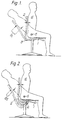
- Figures 1 and 2 illustrate chairs produced according to known technology.
- Figure 3 illustrates a chair according to the invention.
- Figure 4 illustrates adjustment of the back rest of a chair according to the invention.
- Figure 5 illustrates adjustment of the seat of a chair according to the invention.
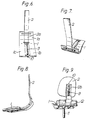
- Figures 6-8 illustrate a modification, diagrammatically shown, of the adjustment mechanism between seat and back rest.
- Figure 9 illustrates a practical embodiment of the chair as shown in Figures 3-5.
- It is commonly known to adjust the angle between the seat 1 and the
back rest 2, and there is a number of mechanical approaches which may mainly be divided into two groups, one of which, shown in Figure 1, has an adjustment axis provided with more consideration for the chair structure than for anatomy. The common turning axis 3 between seat and back rest is located at a relatively large distance from thehip joints 5 of the user of the chair. Whenback rest 2 is tilted backwards, this will cause a displacement d₁ of the point of contact between the back rest and the back of user 4, as will appear from Figure 1. - With another known approach having the turning point of the back rest and, possibly, the seat located beneath the seat surface and, thus, at a considerable distance from said
hip joints 5, saidbearing point 6 will cause the point of contact betweenback rest 2 and the back of user 4 to be displaced over a distance d₂, when the back rest is tilted backwards. In both cases the user will slide forwards on the chair, as shown, due to an unfortunate choice of turning point between seat and back rest. - In Figure 2
axis 6 is, however, located in such a manner that the disproportion between the movements of the chair and of the user's body is slightly reduced as compared to the conditions shown in Figure 1. - Figure 3 shows how the adjustment of angles between seat 1 and
back rest 2 may occur by making the seat and the back rest move along a circular path the imaginary turning point of which is located to coincide with an imaginary axis through thehip joints 5 of the user. As will appear from Figure 4 as well, there will be no resulting sliding movement forwards on the chair and, thus, no displacement between the point of contact of the back rest with the back of the user 4. Furthermore, it will be obvious that the adjusting mechanism of the chair need not be thicker than the supporting back rest/seat shell, as said mechanism may be integrated in the supporting shell of the chair. With the approach shown in Figures 3, 4, and 5 the load on the adjusting mechanism may be reduced, as compared to the existing approaches. Mechanisms for mutual adjustment of the angle between the seat and the back rest may be sliding mechanisms, roller mechanisms with alternately provided rollers, with rollers on one or the other portion, since any possible counter loads may, e.g. be shaped as springs with, or without integrated locking mechanisms, e.g. gas springs. Those skilled in the art, however, may find other technical solutions of a mechanism based on the idea of the present invention. - In Figure 4 angle adjustment between the upper part of the body and the thighs is illustrated. The turning axis between seat 1 and
back rest 2 coincides with thehip joint axis 5 of user 4. It will appear from Figure 4 that theback rest 2 may be adjusted in an angle α₁-α₂. In a similar manner the seat angle may be adjusted in a range of angles b₁-b₂, as shown in Figures 5a and 5b. As will appear from Figure 5b, it will then be natural to adjust the level of the chair seat in a range h₁-h₂. - The mechanism for adjustment of the back rest and the mechanism for adjustment of the seat may be anchored to a common
circular mounting plate 7 which is firmly mounted to mechanism 8 for adjustment of the chair level. Said mechanism for adjusting the level of a chair may, e.g. be a conventional gaslift device or another conventional mechanism for adjusting the level of the chair. - Mounting
plate 7 is adjusted up and down (in case of adjustment of the sitting level) by the aid of an activating handle (not shown) which is activated to release a locking mechanism (not shown) in connection with level adjusting means 8. By the aid of the same activation handle or a separate activation handle a locking mechanism (not shown) for circular movement between said mountingplate 7 and the seat plate 1 may be released. This activation handle may, if desired, be activated in e.g. two steps, the first step actuating seat adjustment and, if desired, mutual back rest adjustment, and the second step actuating level adjustment in addition to said fist step. - As will appear from Figures 4 and 5, the lower portion of said back rest has an arcuate cross section, and the rear portion of the seat has a corresponding arcuate cross section with said portions being located on opposite sides of circle sector shaped mounting
plate 7. In the shown embodiment the arcuate lower portion of the back rest has a slightly larger radius of curvature than that of saidcircular mounting plate 7, whereas the latter has a slightly larger radius of curvature than that of the rear arcuate portion of the seat. - It will appear from Figures 6-8 how the
back rest 2 is arcuate at its lower portion 2a, and how seat 1 is arcuate at its rear portion 1a. Said two portions are, in the shown embodiment, located in the same surface level. This is achieved by, having the seat divided into two separate but connected members 1b and 1c, withback rest 2 arranged between said seat members, as shown. The mutual angular position between seat and back rest is locked by the aid of agas cylinder 9 or another mechanical locking device, and in case of movement between seat and backrest release button 10 is actuated.Gas cylinder 9 is located between the lower front portion 2a of the back rest and the front edge portion of the seat. Those skilled in the art will immediately understand that seat 1 andback rest 2 are shown without any padding, etc. in Figures 6-8. - In Figures 6-8 it is primarily assumed that the seat is fixed or tiltable in a conventional manner, whereas the back rest is adjustable in relation to the seat, as mentioned.
- It should, however, be understood that if the back rest is essentially fixed, at least at its lower portion 2a, the arrangement of Figures 6-8 may be used for tilting the seat 1 relative to back
rest 2. - In the arrangement indicated in Figure 9
gas cylinder 9 is located between an upper backrest frame portion 2b and an upper rear portion (not completely visible) of seat 1. The mutual angle between seat and back rest can, thus, be changed by actuation ofactuator 10. Furthermore, the total position of seat aad back rest in relation to the support may be made variable by providing seat and back rest with slides sliding in guides (not shown) and being operated simultaneously, e.g. by clamping effect exerted by a tensioning means 12, to provide for great friction between said slides and guides. In this manner said total position may be fixed arbitrarily within predetermined limits. - It should, however, be mentioned that, e.g. only the guide of the seat requires a tensioning means 12 as mentioned, the position of
back rest 2 being locked by the aid of saidgas cylinder 9. - It should be understood that the above disclosure and the enclosed drawings are only meant to illustrate the inventive idea without limiting the scope of the invention as defined in the following claims.
- Also, the invention is obviously applicable to most kinds of chairs or body supporting means, e.g. office chairs, resting chairs, passenger chairs, patient chairs, beds and all kinds of devices requiring adjustment of the angle between the upper part and the lower part of the human body.
Claims (7)
4. An adjustable sitting device as defined in claim 1, characterized in a controllable gas cylinder jack (9) entends between a rear region of said seat plates and a rear, upper end (2b) of said back rest plate.
6. An adjustable sitting device as defined in claim 1, charaterized in that a circle section shaped bearing plate (7) being firmly fixed to a chair support is inserted between said portions in order to interactively support these portions.
Applications Claiming Priority (2)
| Application Number | Priority Date | Filing Date | Title |
|---|---|---|---|
| NO861865A NO160896C (en) | 1986-05-09 | 1986-05-09 | ADJUSTABLE SEATING DEVICE. |
| NO861865 | 1986-05-09 |
Publications (2)
| Publication Number | Publication Date |
|---|---|
| EP0277145A1 EP0277145A1 (en) | 1988-08-10 |
| EP0277145B1 true EP0277145B1 (en) | 1991-05-15 |
Family
ID=19888915
Family Applications (1)
| Application Number | Title | Priority Date | Filing Date |
|---|---|---|---|
| EP87902793A Expired EP0277145B1 (en) | 1986-05-09 | 1987-05-06 | An adjustable sitting device |
Country Status (9)
| Country | Link |
|---|---|
| US (2) | US5052753A (en) |
| EP (1) | EP0277145B1 (en) |
| JP (1) | JPS63503284A (en) |
| CA (1) | CA1277220C (en) |
| DE (1) | DE3770150D1 (en) |
| DK (1) | DK6788D0 (en) |
| FI (1) | FI83384C (en) |
| NO (1) | NO160896C (en) |
| WO (1) | WO1987006810A1 (en) |
Families Citing this family (51)
| Publication number | Priority date | Publication date | Assignee | Title |
|---|---|---|---|---|
| DK0517934T3 (en) * | 1991-06-10 | 1995-08-21 | Siemens Ag | Dentist-patient chair with swivel backrest |
| DE4135948C2 (en) * | 1991-10-31 | 1993-12-23 | Rolf Voelkle | Chair, in particular office swivel chair |
| US5320410A (en) * | 1992-01-14 | 1994-06-14 | Steelcase Inc. | Chair control |
| GB9223296D0 (en) * | 1992-11-06 | 1992-12-23 | Univ Loughborough | Ergonomic chair |
| CA2116079C (en) * | 1993-02-22 | 2005-12-27 | Benjamin Cowan | Chair |
| US5511852A (en) * | 1993-02-25 | 1996-04-30 | Herman Miller, Inc. | Adjustable backrest for a chair |
| DE4331987A1 (en) * | 1993-09-21 | 1995-03-23 | Fredi Dubach | Chair, especially office chair |
| US5476306A (en) * | 1994-01-13 | 1995-12-19 | Westinghouse Electric Corporation | Chair back support adjustment mechanism |
| DE4420626C2 (en) * | 1994-06-14 | 1998-12-17 | Grammer Ag | Last actuating device for a vehicle seat |
| US5765914A (en) | 1995-06-07 | 1998-06-16 | Herman Miller, Inc. | Chair with a tilt control mechanism |
| US5577804A (en) * | 1995-06-30 | 1996-11-26 | Global Upholstery Company | Seat height adjustment mechanism for a chair |
| US5899530A (en) | 1995-08-23 | 1999-05-04 | Global Upholstery Company | Control mechanism for a chair |
| US5775774A (en) * | 1996-08-12 | 1998-07-07 | Okano; Hiroshi | Tilt mechanism for chairs |
| DE19724163C1 (en) * | 1997-06-07 | 1998-10-08 | Grammer Ag | Back support frame for motor vehicle seat |
| US6250715B1 (en) | 1998-01-21 | 2001-06-26 | Herman Miller, Inc. | Chair |
| GB2340746B (en) | 1998-07-27 | 2002-02-13 | Ashfield Eng Co Wexford Ltd | A chair |
| CA2302063C (en) * | 2000-03-23 | 2010-08-17 | Cke Technologies Inc. | Ergonomic chair |
| DE10037327A1 (en) * | 2000-07-29 | 2002-02-14 | Keiper Gmbh & Co | Vehicle seat with adjustable seat cushion |
| AU783829B2 (en) | 2000-09-28 | 2005-12-08 | Formway Furniture Limited | A reclinable chair |
| AUPR054400A0 (en) | 2000-09-29 | 2000-10-26 | Formway Furniture Limited | A castor |
| JP3977005B2 (en) * | 2000-10-16 | 2007-09-19 | コクヨ株式会社 | Chair |
| MXPA02005951A (en) * | 2000-10-16 | 2003-10-14 | Kokuyo Kk | Chair. |
| US6820934B2 (en) * | 2000-11-09 | 2004-11-23 | Michigan Tube Swagers & Fabricators, Inc. | Chair having flexible back support |
| US6471293B2 (en) | 2000-11-09 | 2002-10-29 | Michigan Tube Swagers & Fabricators, Inc. | Stackable chair with flexible back support |
| US6805412B2 (en) * | 2001-08-30 | 2004-10-19 | Burgess Furniture Ltd. | Stackable chair with flexible back |
| US7234775B2 (en) * | 2002-06-18 | 2007-06-26 | Hector Serber | Dynamically balanced seat assembly having independently and arcuately movable seat and backrest and method |
| US7226130B2 (en) * | 2002-09-12 | 2007-06-05 | Steelcase Development Corporation | Seating with comfort surface |
| US6869142B2 (en) * | 2002-09-12 | 2005-03-22 | Steelcase Development Corporation | Seating unit having motion control |
| US20050006930A1 (en) * | 2003-03-26 | 2005-01-13 | Graco Children's Products Inc. | High chair |
| US20050017561A1 (en) * | 2003-07-21 | 2005-01-27 | Burmeister Richard F. | Seat, seat recliner mechanism, and seat recliner system |
| CN100374055C (en) * | 2004-07-06 | 2008-03-12 | 林育鸿 | Sample device for controlling angle of chair-back |
| US20060103221A1 (en) * | 2004-10-08 | 2006-05-18 | Ronald Kleist | Ergonomic chair |
| DE102004050853A1 (en) * | 2004-10-18 | 2006-04-20 | Interstuhl Büromöbel GmbH & Co. KG | chair |
| DE202005006960U1 (en) * | 2005-04-28 | 2006-08-31 | Bock 1 Gmbh & Co. Kg | Synchronising mechanism for seat and backrest of office chair has seat support connected to base support on chair column so that backward swivel movement of backrest lifts rear area of seat support and then of front area |
| US20070102979A1 (en) * | 2005-10-25 | 2007-05-10 | GLOBAL TOTAL OFFICE an Ontario limited partnership having GLOBAL UPHOLSTERY CO. | Adjustment mechanism for a chair and method for replacing a telescoping cylinder in a reconfigurable chair |
| DE102006023981A1 (en) * | 2006-05-22 | 2007-12-06 | Wilkhahn Wilkening + Hahne Gmbh & Co. Kg | chair |
| CN102151027B (en) | 2007-01-29 | 2016-03-16 | 赫尔曼米勒有限公司 | Seat structure and using method thereof |
| US7695067B2 (en) * | 2007-03-02 | 2010-04-13 | Goetz Mark W | Ergonomic adjustable chair |
| DE102008011309B3 (en) * | 2008-02-27 | 2009-06-04 | Thonet Gmbh | office chair |
| US20100141002A1 (en) * | 2008-06-04 | 2010-06-10 | Kurrasch Andrew J | Biasing mechanism |
| US8342604B2 (en) * | 2009-02-04 | 2013-01-01 | Cosco Management, Inc. | Juvenile vehicle seat with seat-back channel cover |
| US8944507B2 (en) * | 2009-10-13 | 2015-02-03 | Herman Miller, Inc. | Ergonomic adjustable chair mechanisms |
| WO2015001928A1 (en) * | 2013-07-02 | 2015-01-08 | 本田技研工業株式会社 | Automobile body structure and method for setting strength of front side frame |
| AU2016247797B2 (en) | 2015-04-13 | 2019-08-01 | Steelcase Inc. | Seating arrangement |
| US10966527B2 (en) | 2017-06-09 | 2021-04-06 | Steelcase Inc. | Seating arrangement and method of construction |
| US11259637B2 (en) | 2015-04-13 | 2022-03-01 | Steelcase Inc. | Seating arrangement |
| US10194750B2 (en) | 2015-04-13 | 2019-02-05 | Steelcase Inc. | Seating arrangement |
| US10548399B2 (en) * | 2016-09-14 | 2020-02-04 | Cabela's Llc | Reclining collapsible chair |
| EP4268676A3 (en) | 2019-02-21 | 2024-02-07 | Steelcase Inc. | Body support assembly and methods for the use and assembly thereof |
| US11357329B2 (en) | 2019-12-13 | 2022-06-14 | Steelcase Inc. | Body support assembly and methods for the use and assembly thereof |
| US11154136B2 (en) | 2020-03-12 | 2021-10-26 | Davis Furniture Industries, Inc. | Double shell seat |
Family Cites Families (10)
| Publication number | Priority date | Publication date | Assignee | Title |
|---|---|---|---|---|
| CH66397A (en) * | 1912-12-09 | 1914-09-01 | Chrirurgie Ind G M B H | Operating table |
| DE1229403B (en) * | 1959-01-31 | 1966-11-24 | Recaro G M B H & Co | Articulated fitting for motor vehicle seats |
| DE1248860B (en) * | 1963-06-19 | 1967-08-31 | Kabushiki Kaisha Monta Sersakusho Kyoto (Japan) | Dental treatment chair |
| DE2735522A1 (en) * | 1977-08-06 | 1979-02-15 | Wilde & Spieth | Office chair with fully adjustable backrest - has two interconnected supporting tubes mounted cradle-like in frame head |
| FR2469316A1 (en) * | 1979-11-14 | 1981-05-22 | Faure Bertrand | IMPROVEMENTS ON VEHICLE SEATS INCLUDING A HULL FRAME |
| US4372608A (en) * | 1979-12-06 | 1983-02-08 | Kabushiki Kaisha Morita Seisakusho | Treatment chair |
| US4505513A (en) * | 1980-03-11 | 1985-03-19 | Uop Inc. | Suspension seats for vehicles |
| FR2478982A1 (en) * | 1980-03-26 | 1981-10-02 | Faure Bertrand | IMPROVEMENTS ON SEATS WITH ADJUSTABLE RECLINING BACKREST |
| US4408800A (en) * | 1980-06-11 | 1983-10-11 | American Seating Company | Office chairs |
| NO852035L (en) * | 1985-05-22 | 1986-11-24 | Aronsen G H V | WHEELCHAIR WITH SEATLETS AND CUTTING OPTIONS. |
-
1986
- 1986-05-09 NO NO861865A patent/NO160896C/en not_active IP Right Cessation
-
1987
- 1987-05-01 CA CA000536137A patent/CA1277220C/en not_active Expired - Lifetime
- 1987-05-06 JP JP62502883A patent/JPS63503284A/en active Pending
- 1987-05-06 EP EP87902793A patent/EP0277145B1/en not_active Expired
- 1987-05-06 WO PCT/NO1987/000035 patent/WO1987006810A1/en active IP Right Grant
- 1987-05-06 DE DE8787902793T patent/DE3770150D1/en not_active Expired - Lifetime
-
1988
- 1988-01-04 FI FI880004A patent/FI83384C/en not_active IP Right Cessation
- 1988-01-08 DK DK006788A patent/DK6788D0/en not_active Application Discontinuation
-
1990
- 1990-02-02 US US07/474,311 patent/US5052753A/en not_active Expired - Fee Related
- 1990-08-15 US US07/567,516 patent/US5024484A/en not_active Expired - Lifetime
Also Published As
| Publication number | Publication date |
|---|---|
| NO160896B (en) | 1989-03-06 |
| US5052753A (en) | 1991-10-01 |
| NO160896C (en) | 1989-06-14 |
| JPS63503284A (en) | 1988-12-02 |
| FI880004A0 (en) | 1988-01-04 |
| WO1987006810A1 (en) | 1987-11-19 |
| NO861865L (en) | 1987-11-10 |
| US5024484A (en) | 1991-06-18 |
| DE3770150D1 (en) | 1991-06-20 |
| FI880004A (en) | 1988-01-04 |
| DK6788A (en) | 1988-01-08 |
| CA1277220C (en) | 1990-12-04 |
| EP0277145A1 (en) | 1988-08-10 |
| DK6788D0 (en) | 1988-01-08 |
| FI83384B (en) | 1991-03-28 |
| FI83384C (en) | 1991-07-10 |
Similar Documents
| Publication | Publication Date | Title |
|---|---|---|
| EP0277145B1 (en) | An adjustable sitting device | |
| US6709058B1 (en) | Ergonomic chair | |
| US6189971B1 (en) | Task chair with adjustable seat depth | |
| US5288138A (en) | Reclining chair | |
| US5660439A (en) | Integrated seat and back and mechanisms for chairs | |
| US6644741B2 (en) | Chair | |
| US6357827B1 (en) | Two platform motion seat | |
| US7234768B2 (en) | Reversible chair | |
| CA2394954C (en) | Ergonomic chair | |
| JPH0822250B2 (en) | Chair | |
| GB2109677A (en) | Motorized reclining chair | |
| CA2087981A1 (en) | Work chair, more particularly an office chair | |
| EP0726723A1 (en) | A working chair with synchronous seat and back adjustment | |
| US20010040402A1 (en) | Adjustable split seat | |
| EP0271962A2 (en) | A point-synchronized adjustment device for office chairs | |
| EP0957721B1 (en) | Chair | |
| JP2021510115A (en) | Improved seat, ergonomic chair, or wheelchair seat assembly | |
| EP1243205B1 (en) | A reclining chair having a footrest and clamping device | |
| GB2271053A (en) | Reclining chair | |
| EP1031337A1 (en) | Adjustable chair | |
| JP2961026B2 (en) | A method of supporting a seated person in a chair by a backrest and a chair using the method | |
| KR20130078931A (en) | Chair | |
| JP2806188B2 (en) | Chair | |
| JPH048819Y2 (en) | ||
| KR100254140B1 (en) | Seat |
Legal Events
| Date | Code | Title | Description |
|---|---|---|---|
| PUAI | Public reference made under article 153(3) epc to a published international application that has entered the european phase |
Free format text: ORIGINAL CODE: 0009012 |
|
| 17P | Request for examination filed |
Effective date: 19871223 |
|
| AK | Designated contracting states |
Kind code of ref document: A1 Designated state(s): DE FR GB IT SE |
|
| 17Q | First examination report despatched |
Effective date: 19890928 |
|
| GRAA | (expected) grant |
Free format text: ORIGINAL CODE: 0009210 |
|
| AK | Designated contracting states |
Kind code of ref document: B1 Designated state(s): DE FR GB IT SE |
|
| REF | Corresponds to: |
Ref document number: 3770150 Country of ref document: DE Date of ref document: 19910620 |
|
| ET | Fr: translation filed | ||
| ITF | It: translation for a ep patent filed | ||
| PLBE | No opposition filed within time limit |
Free format text: ORIGINAL CODE: 0009261 |
|
| STAA | Information on the status of an ep patent application or granted ep patent |
Free format text: STATUS: NO OPPOSITION FILED WITHIN TIME LIMIT |
|
| 26N | No opposition filed | ||
| EAL | Se: european patent in force in sweden |
Ref document number: 87902793.6 |
|
| PGFP | Annual fee paid to national office [announced via postgrant information from national office to epo] |
Ref country code: FR Payment date: 19970528 Year of fee payment: 11 |
|
| PG25 | Lapsed in a contracting state [announced via postgrant information from national office to epo] |
Ref country code: FR Free format text: LAPSE BECAUSE OF NON-PAYMENT OF DUE FEES Effective date: 19980531 |
|
| REG | Reference to a national code |
Ref country code: FR Ref legal event code: ST |
|
| REG | Reference to a national code |
Ref country code: GB Ref legal event code: IF02 |
|
| PG25 | Lapsed in a contracting state [announced via postgrant information from national office to epo] |
Ref country code: IT Free format text: LAPSE BECAUSE OF NON-PAYMENT OF DUE FEES;WARNING: LAPSES OF ITALIAN PATENTS WITH EFFECTIVE DATE BEFORE 2007 MAY HAVE OCCURRED AT ANY TIME BEFORE 2007. THE CORRECT EFFECTIVE DATE MAY BE DIFFERENT FROM THE ONE RECORDED. Effective date: 20050506 |
|
| PGFP | Annual fee paid to national office [announced via postgrant information from national office to epo] |
Ref country code: GB Payment date: 20051019 Year of fee payment: 19 |
|
| PGFP | Annual fee paid to national office [announced via postgrant information from national office to epo] |
Ref country code: SE Payment date: 20051026 Year of fee payment: 19 |
|
| PGFP | Annual fee paid to national office [announced via postgrant information from national office to epo] |
Ref country code: DE Payment date: 20051027 Year of fee payment: 19 |
|
| PG25 | Lapsed in a contracting state [announced via postgrant information from national office to epo] |
Ref country code: GB Free format text: LAPSE BECAUSE OF NON-PAYMENT OF DUE FEES Effective date: 20060506 |
|
| PG25 | Lapsed in a contracting state [announced via postgrant information from national office to epo] |
Ref country code: SE Free format text: LAPSE BECAUSE OF NON-PAYMENT OF DUE FEES Effective date: 20060507 |
|
| PG25 | Lapsed in a contracting state [announced via postgrant information from national office to epo] |
Ref country code: DE Free format text: LAPSE BECAUSE OF NON-PAYMENT OF DUE FEES Effective date: 20061201 |
|
| EUG | Se: european patent has lapsed | ||
| GBPC | Gb: european patent ceased through non-payment of renewal fee |
Effective date: 20060506 |