EP0277105A1 - Power tool for two step tightening of screw joints - Google Patents
Power tool for two step tightening of screw joints Download PDFInfo
- Publication number
- EP0277105A1 EP0277105A1 EP88850020A EP88850020A EP0277105A1 EP 0277105 A1 EP0277105 A1 EP 0277105A1 EP 88850020 A EP88850020 A EP 88850020A EP 88850020 A EP88850020 A EP 88850020A EP 0277105 A1 EP0277105 A1 EP 0277105A1
- Authority
- EP
- European Patent Office
- Prior art keywords
- clutch means
- motor
- clutch
- housing
- tightening
- Prior art date
- Legal status (The legal status is an assumption and is not a legal conclusion. Google has not performed a legal analysis and makes no representation as to the accuracy of the status listed.)
- Granted
Links
- 238000000034 method Methods 0.000 claims abstract description 19
- 230000008569 process Effects 0.000 claims abstract description 18
- 230000005540 biological transmission Effects 0.000 claims abstract description 9
- 230000009467 reduction Effects 0.000 claims abstract description 7
- 230000003578 releasing effect Effects 0.000 claims abstract description 6
- 230000033001 locomotion Effects 0.000 claims description 10
- 230000009471 action Effects 0.000 claims description 5
- 238000006243 chemical reaction Methods 0.000 claims description 5
- 206010023230 Joint stiffness Diseases 0.000 description 5
- 238000006073 displacement reaction Methods 0.000 description 4
- 230000008859 change Effects 0.000 description 3
- 230000007246 mechanism Effects 0.000 description 3
- 230000036316 preload Effects 0.000 description 2
- 238000011144 upstream manufacturing Methods 0.000 description 2
- 230000008878 coupling Effects 0.000 description 1
- 238000010168 coupling process Methods 0.000 description 1
- 238000005859 coupling reaction Methods 0.000 description 1
- 230000003247 decreasing effect Effects 0.000 description 1
- 239000012530 fluid Substances 0.000 description 1
- 230000003993 interaction Effects 0.000 description 1
- 230000002093 peripheral effect Effects 0.000 description 1
Images
Classifications
-
- B—PERFORMING OPERATIONS; TRANSPORTING
- B25—HAND TOOLS; PORTABLE POWER-DRIVEN TOOLS; MANIPULATORS
- B25B—TOOLS OR BENCH DEVICES NOT OTHERWISE PROVIDED FOR, FOR FASTENING, CONNECTING, DISENGAGING OR HOLDING
- B25B21/00—Portable power-driven screw or nut setting or loosening tools; Attachments for drilling apparatus serving the same purpose
- B25B21/008—Portable power-driven screw or nut setting or loosening tools; Attachments for drilling apparatus serving the same purpose with automatic change-over from high speed-low torque mode to low speed-high torque mode
-
- B—PERFORMING OPERATIONS; TRANSPORTING
- B23—MACHINE TOOLS; METAL-WORKING NOT OTHERWISE PROVIDED FOR
- B23P—METAL-WORKING NOT OTHERWISE PROVIDED FOR; COMBINED OPERATIONS; UNIVERSAL MACHINE TOOLS
- B23P19/00—Machines for simply fitting together or separating metal parts or objects, or metal and non-metal parts, whether or not involving some deformation; Tools or devices therefor so far as not provided for in other classes
- B23P19/04—Machines for simply fitting together or separating metal parts or objects, or metal and non-metal parts, whether or not involving some deformation; Tools or devices therefor so far as not provided for in other classes for assembling or disassembling parts
- B23P19/06—Screw or nut setting or loosening machines
- B23P19/065—Arrangements for torque limiters or torque indicators in screw or nut setting machines
-
- B—PERFORMING OPERATIONS; TRANSPORTING
- B25—HAND TOOLS; PORTABLE POWER-DRIVEN TOOLS; MANIPULATORS
- B25B—TOOLS OR BENCH DEVICES NOT OTHERWISE PROVIDED FOR, FOR FASTENING, CONNECTING, DISENGAGING OR HOLDING
- B25B23/00—Details of, or accessories for, spanners, wrenches, screwdrivers
- B25B23/14—Arrangement of torque limiters or torque indicators in wrenches or screwdrivers
- B25B23/141—Mechanical overload release couplings
Definitions
- This invention relates to a power tool for two step tightening of screw joints.
- the invention concerns a power tool of the above type incorporating the structural features recited in the preamble of claim 1.
- the problem which is solved by the invention is how to bring down the final torque overshoot at so called stiff screw joints, an overshoot which is caused by the inertia of the rotating parts of the tool.
- stiff joints the torque growth takes place very rapidly, because at these joints there is no deformation sequence during which the kinetic energy of the rotating parts of the tool is absorbed before the final torque level is reached.
- the overshoot problem is particularly significant at electrically powered tightening tools, because the rotating mass of an electric motor is much greater than that of a pneumatic vane motor.
- the tightening process is carried out in two steps, namely a first, high speed step during which the screw joint is run down and tightened up to a snug level, and a second, low speed step during which the desired final torque level is reached. Since the first step ends at a snug level which is just a fraction of the final torque level the kinetic energy of the fast rotating motor and other rotating parts of the tool has practically no possibility at all to influence upon the final torque level, not even at extremely stiff joints. The result is a tightening tool with a very low mean shift, e.i. a tool which delivers torque with a very small or no difference at all between the installed torque at soft joints and the installed torque at stiff joints.
- this known tool comprises not only a torque responsive release clutch but also a freewheel coupling and an extra reduction gearing
- the snug level change of operation into the low speed/high torque mode takes place almost instantaneously, without any intermission in the power supply from the motor of the tool.
- This is a serious disadvantage, because at stiff joints this might cause a substantial over-shoot at the desired final torque level.
- the object of the present invention is to avoid the torque over-shoot problems inherent in the above described prior art.
- the tool shown in Figs 1a and 1b is an angle nut runner comprising a housing 10 in which is supported a rotation motor 11 (not shown in detail), a power transmission connecting the motor 11 to an output shaft 13, and a power supply means 14 located in the rear end of the housing 10.
- the power transmission includes a drive shaft 15 and a clutch means which comprises a driving member 16 and an axially movable yielding element 17 which is preloaded by a spring 26, three conically ended rollers 18 and a transversely displaceable trip element 19.
- the latter has an oblique end surface 20 and is spring biassed into contact with an oblique surface 21 on the yielding element 17.
- the trip element 19 is formed with an axially directed aperture 22.
- a release detecting rod 23 extends axially through the drive shaft 15 and is endwise supported by the trip element 19.
- a driven shaft 24 is provided with a cam portion 25 which forms the driven member of the clutch means and which cooperates with the rollers 18 to transmit torque to the shaft 24.
- the torque transmitting clutch further comprises a ring element 28 which is clamped between the spring 26 and the yielding element 17.
- the pretension of spring 26 is adjustable by means of a nut 29 threaded onto the drive shaft 15.
- a further ring nut 30 is mounted on the drive shaft 15 and carries three axially directed fingers 31 which at their one ends are pivotally supported on the ring nut 30 and at their opposite ends arranged to endwise abut against the ring element 28.
- Each of the axially directed fingers 31 is acted upon by a leaf spring 32 so as to urge the fingers radially inwardly.
- the centrifugal forces acting upon the fingers 31 will overcome the preload generated by the springs 32 and make the fingers 31 move outwardly.
- the ring element 28 comprises an annular shoulder 35 which is somewhat slanted in relation to a diameter plane and arranged to engage the ends of the fingers 31 which are slanted as well to match the shoulder 35.
- a circumferential flange 36 of the ring element 28 serves to limit the outward movement of the fingers 31 as the latters are moved outwardly by centrifugal action.
- annular groove 37 Between the shoulder 35 and the circumferential flange 36 there is an annular groove 37 the width of which is somewhat larger than the thickness of the fingers 31, thereby allowing the fingers 31 to be received in the groove 37 and enable an axial movement of the ring element 28.
- the tool is connected to a screw joint by a nut socket connected to the output shaft 13, and the power supply means 14 is connected to an external power source.
- the torque resistance from the screw joint is very low, which means that the rotation speed of the motor as well as of the clutch means is rather high.
- a centrifugal action on the fingers 31 is big enough to overcome the preload of the leaf springs 32 and move the fingers radially outwardly into contact with the peripheral flange 36 of the ring element 28. Then the ring element 28 is free to be moved axially since the fingers 31 are receivable in the annular groove 37.
- the spring 26 can no longer resist the axial pressure excerted by the rollers 18 upon the yielding element 17 and ring element 28, which results in an axial displacement of the yielding element 17 and the ring element 28 as well as a transverse displacement of the trip element 19.
- the aperture 22 of the latter is brought into alignment with the release detecting rod 23 which falls down and makes the power supply means 14 shut off or at least substantially reduce the power supply to the motor 11.
- the first step of the tightening process is ended and all the rotating parts of the tool comes to a stand still.
- the second step of the tightening process will not be completed as the result of a release of the clutch means as in the first step but is discontinued as a result of a certain torque level being reached and indicated by torque sensors or by a certain indicated change in the power supply.
- a certain torque level being reached and indicated by torque sensors or by a certain indicated change in the power supply.
- the spring biassed fingers 31 are arranged to shift the mode of operation of the clutch means from a torque dependant release action to a locked non-releasing action.
- the power tool illustrated in Figs 4-6 comprises a housing 50 in which is mounted a rotation motor (not shown) which by a drive shaft 51 delivers a torque to a power transmission which includes two planetary reduction gears 52 and 53. The latter is coupled to a driven shaft 54.
- the first planetary gear 52 comprises a planet carrier 56, a number of planet wheels 57 and a ring gear 58 immovably mounted in the housing 50.
- the planet carrier 56 comprises a sun gear 55 for cooperation with the planet wheels 59 of the second planet gear 53.
- the planet wheels 59 are supported by a planet carrier which is formed in one piece with the output spindle 54.
- the second planetary gear 53 also comprises a ring gear 60 which is rotatably supported in the housing 50 as well as axially displaceable relative thereto.
- the ring gear 60 is formed with a flat annular end surface 61 which is broken by two axially extending teeth 62 which are formed with inclined cam surfaces. See Figs 5a-c.
- the immovable ring gear 58 of the first planetary gear 52 has on its left hand end a flat annular end surface 64 which is broken by two axially extending teeth 66 which, similarly to the teeth 62 on the movable ring gear 60, are provided with inclined cam surfaces. Between the two ring gears 60 and 58 there are employed two balls 67 which together with the flat surfaces 61 and 64 form an axial thrust bearing between the two ring gears.
- the ring gear 60 is biassed toward ring gear 58 by means of a spring 68 which via axially extending pins 69 and an axial thrust bearing 80 exerts an axial bias force on the ring gear 60.
- the spring 68 is supported by a flanged nut 63 which is adjustably connected to the housing 50.
- the ring gear 60 is formed with two circumferential grooves 82 and 84, one 82 of which is arranged to be engaged by a release sensing element 83 connected to the power supply means of the tool (not shown), whereas the other groove 84 is arranged to cooperate with a radial stud 85 in the housing 50.
- the groove 84 is larger than the stud 85 both in its axial direction and in its circumferential direction. This stud and groove arrangement is intended on one hand to allow an axial displacement of ring gear 60 during the release sequence of the clutch and on the other hand to limit the rotational movement of ring gear 60 to a certain angular interval after the release sequence.
- the torque supplied by the motor shaft 51 is transmitted via the planetary gears 52 and 53 to the output spindle 54 and further to a screw joint to be tightened.
- a reaction torque is transferred to the ring gear 60.
- the latter is prevented from being rotated by interengagement of its teeth 12, the balls 67 and the teeth 66 of the stationary ring gear 58. Due to the inclined cam surfaces of the teeth 62 and 66 the ring gear 60 tends to move axially as a result of the transferred torque, but the axial bias force provided by the spring 68 keeps the ring gear 60 in its torque transferring position as illustrated in Fig 5a.
- the reaction torque reaches a certain level which is the snug level representing the end of the first step of the tightening process
- the axial force developed on the ring gear 60 will exceed the axial load from the spring 68 and cause an axial movement of the ring gear 60.
- the teeth 62 of the ring gear 60 will override the teeth 66 of the stationary ring gear 58.
- the balls 67 act continously as a roller bearing between the two ring gears 60, 58.
- the ring gear 60 is axially displaced away from the stationary ring gear 58 and causes a motion of the sensing element 83 which will influence upon the power supply means of the rotation motor to, thereby, interrupt or at least substantially reduce the power supply to the latter.
- This axial displacement of the ring gear 60 takes place during a very short period of time though, because as soon as the teeth 62 and 66 have passed each other the ring gear 60 regains its original axial position supporting against the stationary ring gear 58 by means of the balls 67.
- the motor is reversed, and due to the arrangement of a free wheel 88 between the driven shaft 54 and the housing 50 the shaft 54 is locked against rotation in the reverse direction, thereby making the ring gear 60 rotate against its release direction to obtain a reengagement with the ring gear 58 via the teeth 62, 66 and the balls 67.
Landscapes
- Engineering & Computer Science (AREA)
- Mechanical Engineering (AREA)
- Details Of Spanners, Wrenches, And Screw Drivers And Accessories (AREA)
Abstract
Description
- This invention relates to a power tool for two step tightening of screw joints.
- In particular, the invention concerns a power tool of the above type incorporating the structural features recited in the preamble of
claim 1. - The problem which is solved by the invention is how to bring down the final torque overshoot at so called stiff screw joints, an overshoot which is caused by the inertia of the rotating parts of the tool. At stiff joints the torque growth takes place very rapidly, because at these joints there is no deformation sequence during which the kinetic energy of the rotating parts of the tool is absorbed before the final torque level is reached. The overshoot problem is particularly significant at electrically powered tightening tools, because the rotating mass of an electric motor is much greater than that of a pneumatic vane motor.
- In accordance with this invention the tightening process is carried out in two steps, namely a first, high speed step during which the screw joint is run down and tightened up to a snug level, and a second, low speed step during which the desired final torque level is reached. Since the first step ends at a snug level which is just a fraction of the final torque level the kinetic energy of the fast rotating motor and other rotating parts of the tool has practically no possibility at all to influence upon the final torque level, not even at extremely stiff joints. The result is a tightening tool with a very low mean shift, e.i. a tool which delivers torque with a very small or no difference at all between the installed torque at soft joints and the installed torque at stiff joints.
- Two-step tightening is in itself an old and well known technique. For example, in US 3,696,871 there is described a tightening tool having a two-speed gear mechanism which is shifted from a high speed/low torque operation to a low speed/high torque operation as a torque snug level is reached. This shifting of operation mode is accomplished by a torque responsive clutch which at a predetermined torque level disengages, whereby a planetary reduction gearing is engaged in the power transmission to reduce the speed and amplify the torque.
- Apart from the fact that this known tool comprises not only a torque responsive release clutch but also a freewheel coupling and an extra reduction gearing, the snug level change of operation into the low speed/high torque mode takes place almost instantaneously, without any intermission in the power supply from the motor of the tool. This means that the inertia forces from the rotating parts "upstream" of the clutch are not at all reduced, but will add to the drive torque as the second tightening step commences. This is a serious disadvantage, because at stiff joints this might cause a substantial over-shoot at the desired final torque level.
- Instead of employing a gear shift mechanism as described above, other previously known screw joint tightening systems operate in a two-step mode which is accomplished simply by interrupting the power supply to the tool and terminate the first step at a predetermined threshold torque level and after a certain time intermission restart the tool for a second tightening step. A tightening system of this type is disclosed in US 3,965,778. Neither is a system of this type able to avoid torque overshoot at stiff joints. Due to the inertia forces of the rotating parts of the tool, and due to the fact that a high runningdown speed is always used during the first tightening step, the overshoot at the end of the first step sometimes extends beyond the desired final torque level. The reason is that the torque application on the joint is not discontinued fast enough.
- The object of the present invention is to avoid the torque over-shoot problems inherent in the above described prior art.
- It is also an object of the invention to accomplish a power tool for two-step screw joint tightening by which the above mentioned problems are solved and which is of a simple and compact design.
- On the drawings:
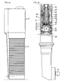
- Figs 1a and 1b show together a side view, partly in section, of a power tool according to the invention.
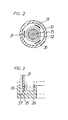
- Fig 2 shows a cross section along line II-II in Fig 1b.
- Fig 3 shows, on a larger scale, a detail of the tool in Fig 1b.
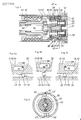
- Fig 4 shows a longitudinal section through a power tool according to another embodiment of the invention.
- Figs 5a-c illustrate schematically the interaction of certain details during operation of the tool.
- Fig 6 shows a cross section along line VI-VI in Fig 4.
- The tool shown in Figs 1a and 1b is an angle nut runner comprising a
housing 10 in which is supported a rotation motor 11 (not shown in detail), a power transmission connecting themotor 11 to anoutput shaft 13, and a power supply means 14 located in the rear end of thehousing 10. - The power transmission includes a
drive shaft 15 and a clutch means which comprises adriving member 16 and an axially movable yieldingelement 17 which is preloaded by aspring 26, three conically endedrollers 18 and a transverselydisplaceable trip element 19. The latter has anoblique end surface 20 and is spring biassed into contact with anoblique surface 21 on the yieldingelement 17. Thetrip element 19 is formed with an axially directedaperture 22. A release detecting rod 23 extends axially through thedrive shaft 15 and is endwise supported by thetrip element 19. A drivenshaft 24 is provided with acam portion 25 which forms the driven member of the clutch means and which cooperates with therollers 18 to transmit torque to theshaft 24. - The torque transmitting clutch further comprises a
ring element 28 which is clamped between thespring 26 and the yieldingelement 17. The pretension ofspring 26 is adjustable by means of anut 29 threaded onto thedrive shaft 15. Afurther ring nut 30 is mounted on thedrive shaft 15 and carries three axially directedfingers 31 which at their one ends are pivotally supported on thering nut 30 and at their opposite ends arranged to endwise abut against thering element 28. Each of the axially directedfingers 31 is acted upon by aleaf spring 32 so as to urge the fingers radially inwardly. At a certain rotation speed of the clutch, however, the centrifugal forces acting upon thefingers 31 will overcome the preload generated by thesprings 32 and make thefingers 31 move outwardly. As could be seen in Figs 4 and 5, thering element 28 comprises anannular shoulder 35 which is somewhat slanted in relation to a diameter plane and arranged to engage the ends of thefingers 31 which are slanted as well to match theshoulder 35. Acircumferential flange 36 of thering element 28 serves to limit the outward movement of thefingers 31 as the latters are moved outwardly by centrifugal action. Between theshoulder 35 and thecircumferential flange 36 there is anannular groove 37 the width of which is somewhat larger than the thickness of thefingers 31, thereby allowing thefingers 31 to be received in thegroove 37 and enable an axial movement of thering element 28. - For carrying out a tightening process, the tool is connected to a screw joint by a nut socket connected to the
output shaft 13, and the power supply means 14 is connected to an external power source. During the first step of the tightening process, the torque resistance from the screw joint is very low, which means that the rotation speed of the motor as well as of the clutch means is rather high. This means in turn that a centrifugal action on thefingers 31 is big enough to overcome the preload of theleaf springs 32 and move the fingers radially outwardly into contact with theperipheral flange 36 of thering element 28. Then thering element 28 is free to be moved axially since thefingers 31 are receivable in theannular groove 37. - As the torque resistance from the screw joint is increased up to a predetermined snug level, the
spring 26 can no longer resist the axial pressure excerted by therollers 18 upon the yieldingelement 17 andring element 28, which results in an axial displacement of the yieldingelement 17 and thering element 28 as well as a transverse displacement of thetrip element 19. Theaperture 22 of the latter is brought into alignment with the release detecting rod 23 which falls down and makes the power supply means 14 shut off or at least substantially reduce the power supply to themotor 11. The first step of the tightening process is ended and all the rotating parts of the tool comes to a stand still. - It is to be noted that the motor and other fast rotating parts of the power transmission "upstream" of the clutch are instantaneously separated from the screw joint connected parts of the tool, which means that there will be no torque over-shoot generated by these fast rotating parts during the deceleration sequence after power shut-off.
- As the second step of the tightening process is commenced, the torque resistance from the screw joint is considerably high and the rotation speed of the power transmission including the clutch means is very low and the
fingers 31 remain in their clutch locking positions. This means that the ends of thefingers 31 abut against theannular shoulder 35 of thering element 28. Hence, thering element 28 is locked against axial movement and the clutch means is prevented from being released. Since the yieldingelement 17 is not able to move axially, therollers 18 can not be moved radially by thecam portion 25 of the drivenshaft 24. This means that the second step of the tightening process will not be completed as the result of a release of the clutch means as in the first step but is discontinued as a result of a certain torque level being reached and indicated by torque sensors or by a certain indicated change in the power supply. As an example of the latter, there could be changes in the back pressure from the motor as in the case a pneumatic motor is used, or a certain increase in the current supply to an electric motor in an electrically powered tool. - Accordingly, the spring biassed
fingers 31 are arranged to shift the mode of operation of the clutch means from a torque dependant release action to a locked non-releasing action. - An important functional feature of the above described two-step tightening process is that before the second step is commenced there is a deceleration sequence during which the rotational speed of the clutch is decreased to a low level at which the mode of operation is changed from releasable to locked condition. This means that the locked second step could not be started until the rotational speed is low enough to avoid addition of inertia generated forces.
- The power tool illustrated in Figs 4-6 comprises a
housing 50 in which is mounted a rotation motor (not shown) which by adrive shaft 51 delivers a torque to a power transmission which includes twoplanetary reduction gears 52 and 53. The latter is coupled to a drivenshaft 54. - The first
planetary gear 52 comprises aplanet carrier 56, a number ofplanet wheels 57 and aring gear 58 immovably mounted in thehousing 50. Theplanet carrier 56 comprises asun gear 55 for cooperation with theplanet wheels 59 of the second planet gear 53. Theplanet wheels 59 are supported by a planet carrier which is formed in one piece with theoutput spindle 54. The second planetary gear 53 also comprises aring gear 60 which is rotatably supported in thehousing 50 as well as axially displaceable relative thereto. At its right hand end, thering gear 60 is formed with a flatannular end surface 61 which is broken by two axially extendingteeth 62 which are formed with inclined cam surfaces. See Figs 5a-c. Theimmovable ring gear 58 of the firstplanetary gear 52 has on its left hand end a flatannular end surface 64 which is broken by two axially extendingteeth 66 which, similarly to theteeth 62 on themovable ring gear 60, are provided with inclined cam surfaces. Between the two ring gears 60 and 58 there are employed twoballs 67 which together with theflat surfaces ring gear 60 is biassed towardring gear 58 by means of aspring 68 which via axially extendingpins 69 and an axial thrust bearing 80 exerts an axial bias force on thering gear 60. Thespring 68 is supported by aflanged nut 63 which is adjustably connected to thehousing 50. - The
ring gear 60 is formed with twocircumferential grooves 82 and 84, one 82 of which is arranged to be engaged by arelease sensing element 83 connected to the power supply means of the tool (not shown), whereas theother groove 84 is arranged to cooperate with aradial stud 85 in thehousing 50. As is illustrated in Figs 5a-c, thegroove 84 is larger than thestud 85 both in its axial direction and in its circumferential direction. This stud and groove arrangement is intended on one hand to allow an axial displacement ofring gear 60 during the release sequence of the clutch and on the other hand to limit the rotational movement ofring gear 60 to a certain angular interval after the release sequence. - In operation, the torque supplied by the
motor shaft 51 is transmitted via theplanetary gears 52 and 53 to theoutput spindle 54 and further to a screw joint to be tightened. As the torque passes through the second planetary reduction gear 53 a reaction torque is transferred to thering gear 60. The latter is prevented from being rotated by interengagement of its teeth 12, theballs 67 and theteeth 66 of thestationary ring gear 58. Due to the inclined cam surfaces of theteeth ring gear 60 tends to move axially as a result of the transferred torque, but the axial bias force provided by thespring 68 keeps thering gear 60 in its torque transferring position as illustrated in Fig 5a. When, however, the reaction torque reaches a certain level which is the snug level representing the end of the first step of the tightening process the axial force developed on thering gear 60 will exceed the axial load from thespring 68 and cause an axial movement of thering gear 60. Thereby, theteeth 62 of thering gear 60 will override theteeth 66 of thestationary ring gear 58. Theballs 67 act continously as a roller bearing between the two ring gears 60, 58. During this overriding sequence, which is illustrated in Fig 5b, thering gear 60 is axially displaced away from thestationary ring gear 58 and causes a motion of thesensing element 83 which will influence upon the power supply means of the rotation motor to, thereby, interrupt or at least substantially reduce the power supply to the latter. This axial displacement of thering gear 60 takes place during a very short period of time though, because as soon as theteeth ring gear 60 regains its original axial position supporting against thestationary ring gear 58 by means of theballs 67. - After this overriding release sequence, there is a short free running sequence before the end surface of the
groove 84 engages thestud 85 and locks thering gear 60 against further rotation. This is illustrated in Fig 5c. Accordingly, thering gear 60 is positively locked against rotation as the second step of the tightening process starts. The second tightening step lasts until a certain torque level is reached. This is indicated by a torque sensor of a conventional type incorporated in the power train of the tool or by a change in the back pressure from the motor in case of a fluid motor being employed or by a certain increase in the electric current in case of an electric motor being employed. - For resetting the clutch mechanism and making it ready for another tightening process, the motor is reversed, and due to the arrangement of a
free wheel 88 between the drivenshaft 54 and thehousing 50 theshaft 54 is locked against rotation in the reverse direction, thereby making thering gear 60 rotate against its release direction to obtain a reengagement with thering gear 58 via theteeth balls 67.
Claims (5)
characterized in that said clutch means (16-18, 25; 58, 60, 67) comprises a shift means (31; 84, 85) by which the mode of operation of said clutch means (16-18, 25; 58, 60, 67) is shiftable between a torque responsive releasing action during the first, high speed step of the tightening process and a non-releasing action during the second, low speed step of the tightening process, and a release detecting means (23; 83) associated with said clutch means (16-18, 25; 58, 60, 67) and arranged to act upon said power supply means to cause at least a substantial reduction of the power supply to said motor as said clutch means (16-18, 25; 58, 60, 67) is released during the first, high speed step of the tightening process.
Applications Claiming Priority (2)
| Application Number | Priority Date | Filing Date | Title |
|---|---|---|---|
| SE8700294A SE461451B (en) | 1987-01-27 | 1987-01-27 | MACHINE TOOLS FOR TWO-STEP TIGHTENING OF SCREW CONNECTIONS |
| SE8700294 | 1987-01-27 |
Publications (2)
| Publication Number | Publication Date |
|---|---|
| EP0277105A1 true EP0277105A1 (en) | 1988-08-03 |
| EP0277105B1 EP0277105B1 (en) | 1990-12-27 |
Family
ID=20367298
Family Applications (1)
| Application Number | Title | Priority Date | Filing Date |
|---|---|---|---|
| EP88850020A Expired EP0277105B1 (en) | 1987-01-27 | 1988-01-20 | Power tool for two step tightening of screw joints |
Country Status (5)
| Country | Link |
|---|---|
| US (1) | US4881435A (en) |
| EP (1) | EP0277105B1 (en) |
| JP (1) | JPS63260769A (en) |
| DE (1) | DE3861383D1 (en) |
| SE (1) | SE461451B (en) |
Cited By (5)
| Publication number | Priority date | Publication date | Assignee | Title |
|---|---|---|---|---|
| FR2658889A1 (en) * | 1990-02-23 | 1991-08-30 | Atlas Copco Tools Ab | TWO SPEED POWER TRANSMISSION FOR A MOTOR TOOL, ESPECIALLY UNDER COMPRESSED AIR. |
| US5155421A (en) * | 1989-06-12 | 1992-10-13 | Atlas Copco Tools Ab | Power wrench for tightening screw joints |
| EP0523477A1 (en) * | 1991-07-15 | 1993-01-20 | C. & E. FEIN GmbH & Co. | Wrench with variable torque adjustment |
| US5738177A (en) * | 1995-07-28 | 1998-04-14 | Black & Decker Inc. | Production assembly tool |
| WO2008068103A1 (en) * | 2006-12-05 | 2008-06-12 | Robert Bosch Gmbh | Handheld tool |
Families Citing this family (28)
| Publication number | Priority date | Publication date | Assignee | Title |
|---|---|---|---|---|
| SE466993B (en) * | 1991-02-18 | 1992-05-11 | Atlas Copco Tools Ab | POWER SCREW CARRIER WITH ADJUSTABLE TORQUE STEERING |
| US5130700A (en) * | 1991-03-04 | 1992-07-14 | Snap-On Tools Corporation | Electronic torque wrench and overshoot compensation circuit therefor |
| US5203242A (en) * | 1991-12-18 | 1993-04-20 | Hansson Gunnar C | Power tool for two-step tightening of screw joints |
| US5730232A (en) * | 1996-04-10 | 1998-03-24 | Mixer; John E. | Two-speed fastener driver |
| US6165096A (en) * | 1999-03-12 | 2000-12-26 | Ingersoll-Rand Company | Self-shifting transmission apparatus |
| US6093128A (en) * | 1999-03-12 | 2000-07-25 | Ingersoll-Rand Company | Ratchet wrench having self-shifting transmission apparatus |
| SE519658C2 (en) * | 2001-07-06 | 2003-03-25 | Atlas Copco Tools Ab | Method and nut puller with target torque detection through sound |
| US7344341B2 (en) * | 2002-11-27 | 2008-03-18 | West Coast Industries, Inc. | Drill |
| SE529478C2 (en) * | 2005-04-28 | 2007-08-21 | Atlas Copco Tools Ab | Connection for connection of a compressed air driven tool with a control unit |
| US7980159B1 (en) | 2005-11-30 | 2011-07-19 | Western Digital Technologies, Inc. | Methods, devices and systems for screw feeding by vacuum and gravity |
| US7458282B1 (en) | 2006-11-21 | 2008-12-02 | Western Digital Technologies, Inc. | Screwdriver comprising a slider having an attached screw bit and a position detector for position feedback |
| US7506553B1 (en) | 2007-06-18 | 2009-03-24 | Western Digital Technologies, Inc. | Methods, devices and systems for adaptively driving screws using a screw driving tool |
| WO2010017371A1 (en) | 2008-08-06 | 2010-02-11 | Milwaukee Electric Tool Corporation | Precision torque tool |
| US8230570B1 (en) | 2009-06-12 | 2012-07-31 | Western Digital Technologies, Inc. | Automatic gravity vacuum screw feeding |
| DE102009054931A1 (en) * | 2009-12-18 | 2011-06-22 | Robert Bosch GmbH, 70469 | Hand-held power tool with a torque coupling |
| EP2635410B1 (en) | 2010-11-04 | 2016-10-12 | Milwaukee Electric Tool Corporation | Impact tool with adjustable clutch |
| US8789446B1 (en) | 2011-06-28 | 2014-07-29 | Western Digital Technologies, Inc. | Screw feeding apparatus to deliver a screw from a vibrating rail to a screw guide tube |
| US9150360B1 (en) | 2013-05-16 | 2015-10-06 | Western Digital Technologies, Inc. | Mechanism to deliver fastener vertically |
| WO2015061370A1 (en) | 2013-10-21 | 2015-04-30 | Milwaukee Electric Tool Corporation | Adapter for power tool devices |
| US9555536B2 (en) * | 2014-06-05 | 2017-01-31 | Hsiu-Lin HSU | Two-stage locking electric screwdriver |
| US10603770B2 (en) | 2015-05-04 | 2020-03-31 | Milwaukee Electric Tool Corporation | Adaptive impact blow detection |
| US10295990B2 (en) | 2015-05-18 | 2019-05-21 | Milwaukee Electric Tool Corporation | User interface for tool configuration and data capture |
| US10217478B2 (en) | 2015-07-10 | 2019-02-26 | Seagate Technology Llc | Linear and rotational adjustment systems |
| CN209189930U (en) | 2016-01-05 | 2019-08-02 | 米沃奇电动工具公司 | Vibration insulating system for electric tool |
| CN108778651B (en) | 2016-02-03 | 2021-06-18 | 米沃奇电动工具公司 | System and method for configuring a reciprocating saw |
| EP3765226B1 (en) | 2018-03-16 | 2023-11-01 | Milwaukee Electric Tool Corporation | Blade clamp for power tool, reciprocating power tool, and method of operating such a blade clamp |
| US11014176B2 (en) | 2018-04-03 | 2021-05-25 | Milwaukee Electric Tool Corporation | Jigsaw |
| USD887806S1 (en) | 2018-04-03 | 2020-06-23 | Milwaukee Electric Tool Corporation | Jigsaw |
Citations (3)
| Publication number | Priority date | Publication date | Assignee | Title |
|---|---|---|---|---|
| US4154308A (en) * | 1977-10-25 | 1979-05-15 | Dresser Industries, Inc. | Low torque automatic screwdriver |
| GB2040768A (en) * | 1979-01-17 | 1980-09-03 | Dresser Ind | Torque responsive shut-off apparatus for pneumatic driven tools |
| EP0092127A2 (en) * | 1982-04-21 | 1983-10-26 | Wagner, Paul-Heinz | Rotary tool |
Family Cites Families (8)
| Publication number | Priority date | Publication date | Assignee | Title |
|---|---|---|---|---|
| SE348395B (en) * | 1969-07-07 | 1972-09-04 | Saab Scania Ab | |
| US4535850A (en) * | 1971-01-06 | 1985-08-20 | Rockwell International Corporation | Power-operated fastener tool |
| BE791093A (en) * | 1971-12-30 | 1973-03-01 | Gardner Denver Co | TOOL SPEED AUTOMATIC VARIATOR |
| US3965778A (en) * | 1974-09-19 | 1976-06-29 | Standard Pressed Steel Co. | Multi-stage tightening system |
| US3960035A (en) * | 1974-11-01 | 1976-06-01 | Gardner-Denver Company | Torque responsive speed shifting mechanism for power tool |
| DE2807677C3 (en) * | 1978-02-23 | 1980-12-04 | Mannesmann Demag Ag, 4100 Duisburg | Hydraulic screwdriver |
| DE2840140A1 (en) * | 1978-09-15 | 1980-03-27 | Schmid & Wezel | PNEUMATIC SCREWDRIVER WITH Bypass |
| US4328871A (en) * | 1980-01-28 | 1982-05-11 | Sps Technologies, Inc. | Power tool speed and torque control mechanism |
-
1987
- 1987-01-27 SE SE8700294A patent/SE461451B/en not_active IP Right Cessation
-
1988
- 1988-01-20 EP EP88850020A patent/EP0277105B1/en not_active Expired
- 1988-01-20 DE DE8888850020T patent/DE3861383D1/en not_active Expired - Lifetime
- 1988-01-21 US US07/146,711 patent/US4881435A/en not_active Expired - Fee Related
- 1988-01-27 JP JP63014797A patent/JPS63260769A/en active Pending
Patent Citations (3)
| Publication number | Priority date | Publication date | Assignee | Title |
|---|---|---|---|---|
| US4154308A (en) * | 1977-10-25 | 1979-05-15 | Dresser Industries, Inc. | Low torque automatic screwdriver |
| GB2040768A (en) * | 1979-01-17 | 1980-09-03 | Dresser Ind | Torque responsive shut-off apparatus for pneumatic driven tools |
| EP0092127A2 (en) * | 1982-04-21 | 1983-10-26 | Wagner, Paul-Heinz | Rotary tool |
Non-Patent Citations (1)
| Title |
|---|
| "Hutte" Vol. IIa, edition 28 Verlag: Wilhelm Ernst & Sohn, Section 9, Regelungstechnik, chapter IIa pages 1253, 1254 * 1. Ausfuhrung von Drehzahlreglern; Fig. 2 * * |
Cited By (6)
| Publication number | Priority date | Publication date | Assignee | Title |
|---|---|---|---|---|
| US5155421A (en) * | 1989-06-12 | 1992-10-13 | Atlas Copco Tools Ab | Power wrench for tightening screw joints |
| FR2658889A1 (en) * | 1990-02-23 | 1991-08-30 | Atlas Copco Tools Ab | TWO SPEED POWER TRANSMISSION FOR A MOTOR TOOL, ESPECIALLY UNDER COMPRESSED AIR. |
| EP0523477A1 (en) * | 1991-07-15 | 1993-01-20 | C. & E. FEIN GmbH & Co. | Wrench with variable torque adjustment |
| US5738177A (en) * | 1995-07-28 | 1998-04-14 | Black & Decker Inc. | Production assembly tool |
| WO2008068103A1 (en) * | 2006-12-05 | 2008-06-12 | Robert Bosch Gmbh | Handheld tool |
| US8083006B2 (en) | 2006-12-05 | 2011-12-27 | Robert Bosch Gmbh | Hand-held power tool |
Also Published As
| Publication number | Publication date |
|---|---|
| SE461451B (en) | 1990-02-19 |
| US4881435A (en) | 1989-11-21 |
| SE8700294D0 (en) | 1987-01-27 |
| JPS63260769A (en) | 1988-10-27 |
| SE8700294L (en) | 1988-07-28 |
| EP0277105B1 (en) | 1990-12-27 |
| DE3861383D1 (en) | 1991-02-07 |
Similar Documents
| Publication | Publication Date | Title |
|---|---|---|
| EP0277105B1 (en) | Power tool for two step tightening of screw joints | |
| US4842078A (en) | Screw joint tightening power tool | |
| US4834192A (en) | Two-speed power tool | |
| US6062114A (en) | Power nutrunner | |
| US5203242A (en) | Power tool for two-step tightening of screw joints | |
| EP0886560B1 (en) | Power nutrunner with torque release clutch and a setting tool | |
| EP0226426B1 (en) | Two speed gearbox | |
| US5385512A (en) | Transmission for electrically driven tool | |
| US4429591A (en) | Drive shifting apparatus for valve control and the like | |
| CA1276818C (en) | Adjustable motor-operated screw driving device | |
| US4429775A (en) | Clutch type torque control device for air driver | |
| SE440989B (en) | SCREW, NUT BEARING WITH TEMPORARY DEVICING MECHANISM | |
| US5201374A (en) | Screw joint tightening power tool | |
| US6662882B2 (en) | Power nut runner with torque responsive power shut-off capacity | |
| SE441989B (en) | PNEUMATIC NUT BEARING FOR TWO SPEEDS | |
| US5083990A (en) | Two-speed power transmission for a power tool | |
| US3507173A (en) | Two-speed nut-runner having two air motors acting as main and auxiliary drivers of a dual-drive planetary gear system | |
| US3220526A (en) | One shot clutch | |
| EP1245340A2 (en) | Portable power tool for mounting via a press fit a machine part onto a shaft | |
| US4191282A (en) | Device for tightening a screw joint | |
| EP0500511B1 (en) | Power wrench | |
| US5379623A (en) | Radial milling head | |
| JPS6147961B2 (en) | ||
| JP3325035B2 (en) | Power tool for screw connection | |
| SU1692751A1 (en) | Turret head |
Legal Events
| Date | Code | Title | Description |
|---|---|---|---|
| PUAI | Public reference made under article 153(3) epc to a published international application that has entered the european phase |
Free format text: ORIGINAL CODE: 0009012 |
|
| AK | Designated contracting states |
Kind code of ref document: A1 Designated state(s): DE FR GB IT |
|
| 17P | Request for examination filed |
Effective date: 19890116 |
|
| 17Q | First examination report despatched |
Effective date: 19900214 |
|
| GRAA | (expected) grant |
Free format text: ORIGINAL CODE: 0009210 |
|
| ITF | It: translation for a ep patent filed | ||
| AK | Designated contracting states |
Kind code of ref document: B1 Designated state(s): DE FR GB IT |
|
| REF | Corresponds to: |
Ref document number: 3861383 Country of ref document: DE Date of ref document: 19910207 |
|
| ET | Fr: translation filed | ||
| PLBE | No opposition filed within time limit |
Free format text: ORIGINAL CODE: 0009261 |
|
| STAA | Information on the status of an ep patent application or granted ep patent |
Free format text: STATUS: NO OPPOSITION FILED WITHIN TIME LIMIT |
|
| 26N | No opposition filed | ||
| ITTA | It: last paid annual fee | ||
| PGFP | Annual fee paid to national office [announced via postgrant information from national office to epo] |
Ref country code: GB Payment date: 19940111 Year of fee payment: 7 Ref country code: FR Payment date: 19940111 Year of fee payment: 7 |
|
| PGFP | Annual fee paid to national office [announced via postgrant information from national office to epo] |
Ref country code: DE Payment date: 19940121 Year of fee payment: 7 |
|
| PG25 | Lapsed in a contracting state [announced via postgrant information from national office to epo] |
Ref country code: GB Effective date: 19950120 |
|
| GBPC | Gb: european patent ceased through non-payment of renewal fee |
Effective date: 19950120 |
|
| PG25 | Lapsed in a contracting state [announced via postgrant information from national office to epo] |
Ref country code: FR Effective date: 19950929 |
|
| PG25 | Lapsed in a contracting state [announced via postgrant information from national office to epo] |
Ref country code: DE Effective date: 19951003 |
|
| REG | Reference to a national code |
Ref country code: FR Ref legal event code: ST |
|
| PG25 | Lapsed in a contracting state [announced via postgrant information from national office to epo] |
Ref country code: IT Free format text: LAPSE BECAUSE OF NON-PAYMENT OF DUE FEES;WARNING: LAPSES OF ITALIAN PATENTS WITH EFFECTIVE DATE BEFORE 2007 MAY HAVE OCCURRED AT ANY TIME BEFORE 2007. THE CORRECT EFFECTIVE DATE MAY BE DIFFERENT FROM THE ONE RECORDED. Effective date: 20050120 |